Table of Contents
Advertisement
FY-Series Digital PID Controller
OT1
400
OT2
AT
OUT1 OUT2
A T
AL1
400
OUT1
AL2
0
20
PRO
RESET
AUTO
RESET
GOLINK
GOLINK
FY400
FY700
48x48
72X72
(DIN 1/16)
(DIN 3/16)
Operation Manual
800
800
700
OUT1
OUT2
A T
AL2
AL3
MAN
700
OUT1
0
20
40
60
AL1
AL2
AL3
MAN
PRO
AUTO
%
40
60
80
100
RESET
GOLINK
FY800
48X96
(DIN 1/8)
900
900
AL1
PRO
OUT1 OUT2
A T
AL1
AL2
OUT1
%
0
20
40
60
80
100
RESET
AUTO
GOLINK
FY900
96X96
(DIN 1/4)
AL3
MAN
PRO
%
80
100
600
600
GOLINK
FY600
96X48
(DIN 1/8)
NOVEMBER, 2005
FY_OPER_EN_V4
%
100
OUT1
OUT2
80
AL1
AL2
60
RESET
40
AL3
MAN
20
AUTO
A T
PRO
0
OUT1
Advertisement
Table of Contents

Related Manuals for Taie FY Series


Summary of Contents for Taie FY Series
- Page 1 FY-Series Digital PID Controller Operation Manual OUT1 OUT2 OUT1 OUT2 OUT1 OUT1 OUT1 OUT2 OUT1 OUT2 RESET AUTO RESET AUTO OUT1 AUTO RESET RESET AUTO RESET OUT1 GOLINK GOLINK GOLINK GOLINK GOLINK FY400 FY700 FY800 FY900 FY600 48x48 72X72 48X96 96X96 96X48 (DIN 1/16)
-
Page 2: Table Of Contents
CONTENT Notice before start- up ……………………………………………………… Page 3 Specifications ………………………………………………………………… Page 4 Terminal arrangement 3.1 FY400 Terminals ……………………………………………………… Page 6 3.2 FY600 Terminals ……………………………………………………… Page 7 3.3 FY700 Terminals ……………………………………………………… Page 8 3.4 FY800 Terminals ……………………………………………………… Page 9 3.5 FY900 Terminals ……………………………………………………… Page 10 External dimension and panel cutout ……………………………………... - Page 3 11 Heater Break Alarm(HBA) ……………………………………………… Page 31 12 Error codes ………………………………………………………………… Page 32 13 Modify input type: TC, RTD ……………………………………………… Page 33 14 Modify input type: Linear Input (mA ,V) 14.1 Hardware ……………………………………………………………… Page 34 14.2 Calibration ……………………………………………………………… Page 35 15 Modify output type: Relay, SSR, 4~20mA …………………………………...
-
Page 4: Notice Before Start-Up
1. Notice before start-up FY series controller has got the CE approvals as below: LDV: D/N EN61010-1 EMC: EN 55 022 1994 /A1:1995/ A2:1997 EN 61 000-3-2: 1995 / -3-3: 1995 EN 61 000-4-2: 1995 / -4-3: 1996 / -4-5: 1995 / -4-6 1996 / -4-8:... -
Page 5: Specifications
1. Specifications Standard spec. Model FY400 FY600 FY700 FY800 FY900 48X48mm 96X48mm 72X72mm 48X96mm 96X96mm Dimension AC 85~265V,DC 15~50V (Option) Supply voltage 50 / 60 HZ Frequency approx 3VA approx 4VA approx 3VA approx 4VA approx 4VA Power consumption 0.2 % FS ± 1digit Accuracy 250ms Sample time... - Page 6 4~20mA , 0~20mA , 0~1V , 0~5V , 0~10V , 1~5V , 2~10V 4~20mA , 0~20mA , 0~1V , 0~5V , 0~10V , 1~5V , 2~10V Remote SV Protocol : MODBUS RTU , MODBUS ASCII , TAIE Communication RS232 , RS485 , TTL Baud rate: 2400 , 4800 , 9600 , 19200 , 38400 bps.
-
Page 7: Terminal Arrangement
3. Terminal arrangement 3.1 FY400 Terminals ( 48mm x 48mm , DIN 1/16 ) A.Power Supply AC 85~265V DC 15 ~50V(Option) H.CT Input B.Control Output C.Input TC,mV mA,V OUT1 OUT2 Relay SSR mA,V Relay SSR mA,V D.Alarm (Use OUT1 & OUT2) (Option) AL 1 AL 2... -
Page 8: Fy600 Terminals
3.2 FY600 Terminals ( 96mm x 48mm , DIN 1/8 ) A.Power Supply AC 85~265V DC 15 ~50V(Option) H.CT Input B.Control Output C.Input TC,mV mA,V OUT1 OUT2 Relay SSR mA,V Relay SSR mA,V D.Alarm E.Transmission AL 1 AL 2 AL 3 (Option) OUT1 OUT1... -
Page 9: Fy700 Terminals
3.3 FY700 Terminals ( 72mm x 72mm) A.Power Supply AC 85~265V DC 15 ~50V(Option) H.CT Input B.Control Output C.Input TC,mV mA,V OUT1 OUT2 Relay SSR mA,V Relay SSR mA,V D.Alarm E.Transmission AL 1 AL 2 (Option) OUT1 OUT1 OUT1 (Proportional Motor (1ΦZero Cross (1ΦPhase Angle Control) -
Page 10: Fy800 Terminals
3.4 FY800 Terminals ( 48mm x 96mm , DIN 1/8 ) A.Power Supply AC 85~265V DC 15 ~50V(Option) H.CT Input B.Control Output C.Input TC,mV mA,V OUT1 OUT2 Relay SSR mA,V Relay SSR mA,V D.Alarm E.Transmission AL 1 AL 2 AL 3 (Option) OUT1 OUT1... -
Page 11: Fy900 Terminals
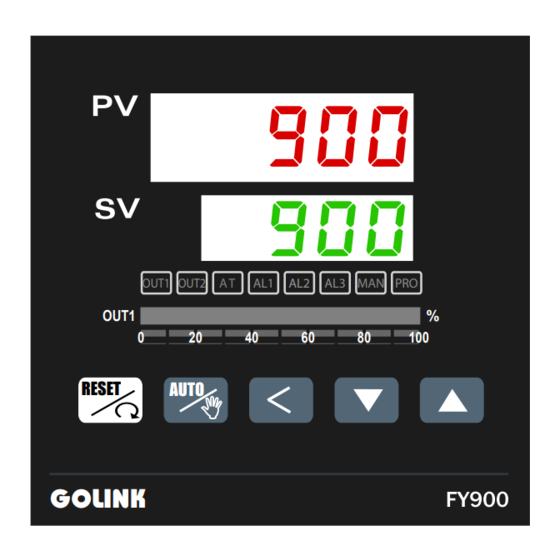
3.5 FY900 Terminals ( 96mm x 96mm , DIN 1/4 ) A.Power Supply E.Transmission AC 85~265V DC 15 ~50V(Option) H.CT Input F.Remote Remote SV B.Control Output C.Input OUT1 OUT1 TC,mV mA,V OUT1 Relay SSR mA,V (1ΦZero (3ΦZero Cross Control) Cross Control) OUT2 D.Alarm Relay SSR mA,V... -
Page 12: External Dimension And Panel Cutout
4. External dimension and panel cutout〈 〈 Unit: : mm〉 〉 44.5+0.5 44.5+0.5 FY400 RESET GOLINK 90.5+0.5 FY600 44.5+0.5 OUT1 OUT2 RESET AUTO OUT1 GOLINK 68.5+0.5 FY700 68.5+0.5 OUT1 OUT2 OUT1 RESET AUTO GOLINK 44.5+0.5 90.5+0.5 FY800 OUT1 OUT2 OUT1 AUTO RESET GOLINK... -
Page 13: Parts Description
5. Parts description GOLINK FY800 FY700 / FY900 FY600 10 11 12 13 14 15 FY400 11 8 9 12 16 5 OUT1 OUT2 RESET OUT1 OUT2 AUTO OUT1 OUT1 OUT2 RESET OUT1 OUT1 GOLINK GOLINK AUTO 4 3 6 13 10 15 14 3 5 6 7 RESET... -
Page 14: Operations
6. Operations Power On Controller will display as below OUT1 OUT2 MAN PRO OUT1 OUT2 MAN PRO OUT1 OUT2 MAN PRO OUT1 OUT2 MAN PRO OUT1 OUT1 OUT1 OUT1 RESET AUTO RESET AUTO RESET AUTO RESET AUTO GOLINK GOLINK GOLINK GOLINK Display input type Display range... -
Page 15: Autotuning (At)
Autotuning (AT) Use AT function to automatically calculate and set the optimize PID value for your system. OUT1 OUT2 MAN PRO OUT1 OUT2 MAN PRO OUT1 OUT2 MAN PRO OUT1 OUT2 MAN PRO OUT1 OUT1 OUT1 OUT1 RESET RESET AUTO AUTO RESET AUTO... -
Page 16: Programmable Ramp / Soak
Programmable RAMP / SOAK (Only available for PFY model) *For detail of the programmable instruction, please refer with page 25. Assume the temperature profile is as below (use total 4 segments ) RAMP SOAK RAMP SOAK TIME 1 hour and 1 hour minutes minutes... -
Page 17: Operation Levels
7. Operation levels Levels diagram Level 1 (User Level) LCK = 0000 Press Key+ 5 seconds Press Key 5 seconds Level 3 Level 2 (Input Level) (PID Level) Press Press Key+ 5 seconds Key 5 seconds LCK = 1111 Press Key + 5 seconds * The controller returns to Level 1 if there... -
Page 18: Parameters
8. Parameters Level 1 (User Level) Process Value Set Value Output Limt Autotuning Alarm 1 set value Heater current display HBA set value Alarm 2 set value Alarm 3 set value... -
Page 19: Level 2 (Pid Level)
LEVEL 2 (PID Level) To enter level 2, press SET key 5 seconds in level 1 8.2.1 Level 2 parameters display / hiding condition 1. Press key 5 seconds to enter level 2. 1. Press key 5 seconds to enter level 2. 2. -
Page 20: Description Of Parameters
8.2.2 Description of parameters Range:0.0~200.0% Proportional band 1 ON/OFF control if set to 0 (0.0) (For output 1) Range:0~3600 seconds Integral time 1 (For output 1) PD control if set to 0 Derivative time 1 Range:0~900 seconds (For output 1) PI control if set to 0 Reserved Reserved...
Need help?
Do you have a question about the FY Series and is the answer not in the manual?
Questions and answers