CHC i80 Quick Start Manual
Hide thumbs
Also See for i80:
- User manual (103 pages) ,
- Maintenance manual (13 pages) ,
- Quick manual (10 pages)
Table of Contents
Advertisement
Quick Links
Advertisement
Table of Contents

Related Manuals for CHC i80


Summary of Contents for CHC i80
- Page 1 CHC i80 GNSS Receiver Quick Start Guide...
- Page 2 Copyright Copyright 2018 eGPS Solutions, Inc. | All rights reserved. Trademarks All product and brand names mentioned in this publication are trademarks of their respective holders. Safety Warnings The Global Positioning System (GPS) is operated by the U.S. Government, which is solely responsible for the accuracy and maintenance of the GPS network.
-
Page 3: Table Of Contents
2.3.2. External Power Supply......2.4. Inserting Battery and SIM Card......2.5. Product with Accessories........2.6. Connecting to an Office Computer....2.7. Connecting to Carlson SurvCE as a Network Rover..............A. Communication Ports Definition A.I. CHC i80 Receiver I/O Port (7-Pin Lemo Port) Definition.......... - Page 4 A.II. CHC i80 Receiver USB Port (7-Pin Lemo Port) Definition........B. i80 Specifications............C. Contact Information.............
-
Page 5: Introduction
1. Introduction The CHC i80 GNSS Receiver Quick Start Guide describes how to set up and use the CHC i80 GNSS receiver. “The receiver” refers to the CHC i80 GNSS receiver unless otherwise stated. Even if you have used other Global Navigation Satellite... -
Page 6: Use And Care
Bluetooth ® operates in license-free bands. Before operating a CHC i80 GNSS receiver, determine if authorization or a license to operate the unit is required in your country. It is the responsibility of the end-user to obtain an operator’s permit or license for the... -
Page 7: Your Comments
2. Getting Started with the CHC i80 2.1. About the Receiver The CHC i80 GNSS receiver incorporates a GNSS engine, GNSS antenna, internal radio, 3G cellular modem, Bluetooth, WiFi and battery in a ruggedized and miniature unit. Either unit may be a base, rover, or used without other devices for static collection. -
Page 8: Parts Of The Receiver
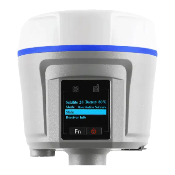
2.2. Parts of the Receiver The operating controls are all located on the front panel. Battery compartment and SIM card slot are located on the back. Serial ports and connectors are located on the bottom of the unit. 2.2.1. Front Panel The following figure shows a front view of the receiver. - Page 9 Icon Light Light Status Description Color 1. Satellites Blue Flash every Each satellite second found 2. Corrections Green Flash every Base is second transmitting the corrections Green Flash every Rover is second receiving the corrections NOTE - The screen display comes up and notifies “Battery Low”...
- Page 10 Function Button Power Button Name Description Function Button Press and hold for 5 seconds to start and stop static sessions. Power Button Works as a Power button: Press and hold this button for 3 seconds to turn on or turn off the receiver Works as a Reset button: Hold Function button and press...
-
Page 11: Lower Housing
2.2.2. Lower Housing The lower housing contains one TNC radio antenna connector, two communication and power ports, one 5/8 - 11 threaded insert and nameplate. SIM card slot and battery compartment are located on the back. 2.2.3. Receiver Ports Continued on the next page... - Page 12 Port Name Description I/O Port This port is a 7-pin Lemo connector that supports RS-232 communications and external power. Users can use the optional GPS to PC Data Cable to realize RS-232 communications between the receiver and computer or controller. Also, users can use the 7-pin cable to transmit differential data to an external radio.
-
Page 13: Batteries And Power
Do not charge or use the battery if it appears to be damaged or leaking. • Charge the lithium-ion battery only in a CHC i80 charger that is specified to charge it. Be sure to follow all instructions that are provided with the battery charger. -
Page 14: Battery Safety
2.3.1.2. Battery Safety WARNING - Do not damage the rechargeable lithium-ion batteries. A damaged battery can cause an explosion or fire and can result in personal injury and/or property damage. To prevent injury or damage: • Do not use or charge the battery if it appears to be damaged. -
Page 15: External Power Supply
2.3.2. External Power Supply Two methods are available for providing external power to the receiver. Use the included GPS to USB PC Data Cable with Power Adapter and either the wall charging adapter or the optional 12 volt battery cable. In the office: The Power Adapter is connected with AC power of 100 - 240 V and the output port of the Power Adapter... -
Page 16: Inserting Battery And Sim Card
2.4. Inserting Battery and SIM Card Push down on the button on the battery cover to open the cover. Align the connectors of the batteries with the connections on the receiver and snap the batteries in place. Snap the battery cover back into place when finished. To remove the batteries, push down on the button on the battery cover and open the cover. -
Page 17: Product With Accessories
2.5. Product with Accessories Item Picture CHC i80 GNSS Receiver UHF Bar Antenna (450-470 MHz) P/N: 2004 020 011 USB Cable with Power Socket P/N: 2004 030 032/ 0403 000 097 Serial Cable with Power Socket P/N: 2004 030 044/... -
Page 18: Connecting To An Office Computer
2.7. Connecting to Carlson SurvCE as a Network Rover Turn on the controller → run SurvCE → tap the Equip tab in the main menu. In the Equip screen, select the GPS Rover button. For the Manufacture field, select CHC and i80 for the Model field. - Page 19 Tap the Comms Tab next to the Current tab. Then select Bluetooth for the Communication Type and Windows Mobile for the BT Type. Press the hammer and wrench button to search for Bluetooth devices. Press the Find Device button to search for devices. Pick your receiver from the list of devices found, the format is GNSS-???????.
- Page 20 After selecting your receiver, press the Set Device PIN button and enter 1234 for the device pin. Press the green check mark and then the Bluetooth button to the left of the red X. Before moving to the Receiver tab, press the button to connect to the receiver, and wait for a successful connection.
- Page 21 Measurement Unit) check box if you intend to use automatic level checking (additional configuration and settings required). To configure the i80 as a network rover, select Data Collector Internet for the Device field and NTRIP for the Network field. Press the hammer and wrench icon to add NTRIP broadcasters to the list of selectable broadcasters.
- Page 22 After selecting the base, or virtual base (eGPSVRS) in this case, the information about the base will be filled in, and you can press the green check mark to return to the RTK tab. Pressing the green check mark from the RTK tab will activate the connection, and you should be on your way to a FIXED position!
-
Page 23: Communication Ports Definition
A. Communication Ports Definition A.I. CHC i80 Receiver I/O Port (7-Pin Lemo Port) Definition Function Ground ( - ) Ground ( - ) RS232-TX (Output) Not Used Not Used RS232-RX (Input) A.II. CHC i80 Receiver USB Port (7-Pin Lemo Port) - Page 24 B. i80 Specifications GNSS Specifications 220 channels with simultaneously tracked satellite signals L1 C/A, L2E, L2C, L5 GLONASS L1 C/A, L1 P, L2 C/A, L2 P, L3 BeiDou B1, B2 Galileo E1, E5A, E5B SBAS L1 C/A, L5 (QZSS, WAAS,...
- Page 25 Protected TNC Female Standard Internal Rx/Tx: 410 MHz to 470 MHz Transmit power: 0.5 W to 2 W Protocol: CHC, Trimble, Pacific Crest Range: 5 km optimal conditions FCC Certified Internal Rx/Tx: 403 MHz to 473 MHz Transmit power: 0.1 W to 1 W...
- Page 26 Environment Operating Temperature -40 °C to +75 °C (-40 °F to 167 °F) Storage Temperature -55 °C to +85 °C (-67 °F to 185 °F) Humidity 100% condensation Waterproof & Dustproof IP68 - protected from temporary immersion to depth of 1.5 meters Drop 2 m protection Electrical Specifications...
- Page 27 C. Contact Information eGPS Solutions, Inc. 4317 Park Drive Suite 104 Norcross, GA 30093 Telephone: (770) 695-3361 Web: www.egps.net Email: info@egps.net...
Need help?
Do you have a question about the i80 and is the answer not in the manual?
Questions and answers