Table of Contents
Advertisement
Advertisement
Table of Contents

Related Manuals for CHC X91GNSS


Summary of Contents for CHC X91GNSS
- Page 1 ETTING TARTED UIDE X91GNSS...
- Page 2 FCC Notice CHC X91 receivers comply with the limits for a Class B digital device, pursuant to the Part 15 of the FCC rules when it is used in the Portable Mode. Operation is subject to the following two conditions: (1) This device may not cause harmful interference and (2) this device must accept any interference received, including interference that may cause undesired operation.
-
Page 3: Table Of Contents
5. CONFIGURATION AND OPERATION ..................19 5.1 Static Configuration ....................19 5.2 Real-Time Kinematic Configuration ................19 5.2.2 Datalink setting ....................21 Appendix A Log Controller on Internet ................25 Appendix B CHC receiver 10 PIN LEMO definition ............. 27... -
Page 4: Introduction
This Getting Started Guide is designed to help you to rapidly familiarize yourself with your new equipment. Only a selection of the many CHC X91 GNSS functions is presented in this guide. 1.1 Technical Assistance If you have a problem and cannot find the information you need in... -
Page 5: Regulations And Safety
Introduction WARNING-A Warning alerts you to a likely risk of serious injury to your person and/or damage to the equipment. CAUTION- A Caution alerts you to a possible risk of serious injury to your person and/or damage to the equipment. 1.3.2 Regulations and Safety The receivers contain integral Bluetooth®... -
Page 6: General Information
General Information 2. GENERAL INFORMATION Overview The X91 receiver provides the following features: Centimeter-accuracy, real-time positioning with RTK/OTF data. Sub-meter-accuracy, real-time positioning using pseudo-range corrections. Automatic OTF initialization while moving Single Lithium-ion rechargeable battery Cable-free Bluetooth® communications with the data controllers ... - Page 7 General Information Vertical: ± (5+1ppm) RMS Baseline Length: ≤300km Data Format RTCM2.1, RTCM2.3, RTCM3.0, CMR, RTCA, Input and Output NMEA0183 outputs, GSOF outputs Physical Reference Size (H×D): 80mm×180mm Weight: 1.25Kg (Battery Included) Electrical Reference ...
-
Page 8: Product Basic Supply Accessories
-GLOVE-B: Simultaneous L1 CBOC, E5A, E5B, E5AltBOC Product Basic Supply Accessories The tables below provide an overview of the different items composing the CHC X91 Base Kit. Basic Supply is the standard accessories for each kit. Base Kit Basic Supply... - Page 9 General Information Rover Kit Basic Supply Item Picture CHC X91GNSS Receiver Rover Lithium Battery Battery Charger Power Adapter with Cord GPS to PC Data Cable Receiving Radio Antenna Connector 2M Range Pole...
- Page 10 General Information Datalink Kit Basic Supply Item Picture CHC DL3 Datalink GPS to Datalink Cable Standard Datalink Antenna with 5 Meter Cable External Power Cable Datalink Antenna Mounting Pole Pole Mounting...
-
Page 11: Product Option Supply Accessories
General Information Product Option Supply Accessories You may have one of the 4 Handheld Controllers depending on different requirement and purchase. LT30 Controller Kit Basic Item Picture Supply LT30 Survey RTK Controller(the controller is different according to your order, you may order Getac or Recon 400) USB Data Cable of Controller Battery Charger and Adapter of... - Page 12 General Information Also there are some more Accessories for your consideration. Transportation Cases Options and Accessories Options are depending on different orders requirements. Transportation Cases Item Picture Options Transport Case Carry Pouch Metal Transport Case for Poles and Antenna Accessories Options Item Picture Double Bubbles Tribrach with...
-
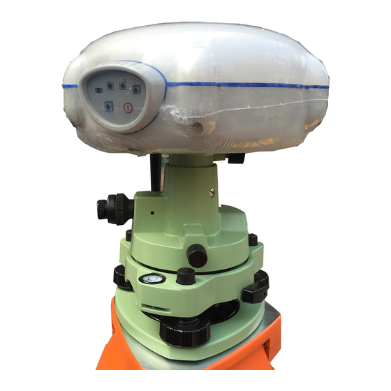
Page 13: Product View
Switch Button (RTK/Static) (On/off) Power Button To turn on X91GNSS, quick press the power button until the power LED (red) lights up. After the receiver powers on, the other three LED will flash together for one time. Switch Button The function of switch button is to switch X91GNSS from RTK mode to static mode. - Page 14 CAUTION: When checking is going on, do not long press, otherwise RTK mode will be activated. Power LED (RED) The indicator to show whether X91GNSS is on or off. When battery is less than 20%, the power LED will flash continuously which reminds you to change the battery.
-
Page 15: Software Installation
Product View It allows you to connect a radio whip antenna to the X91GNSS. There is only one type of CHC radio antenna connection --- TNC. Adaptor The 5/8” adaptor is used for setting up the receiver on the tripod. -
Page 16: Batteries And Power
Do not charge or use the battery if it appears to be damaged or leaking. Charge the Lithium-ion battery only in a CHC product that is specified to charge it. Be sure to follow all instructions that are provided with the battery charger. -
Page 17: External Power Supply
3.3.1 External Power supply We have two methods to provide the external power to the receiver by the CHC GPS to PC cable+ Power Adapter or CHC GPS to PC cable+ external power cable (option purchase)+ car battery. ... - Page 18 Product View The rechargeable Lithium-ion battery is supplied partially charged. The following recommendations provide optimal performance and extend the life of your batteries: Fully charge all new batteries prior to use. Do not allow the batteries to discharge below 5 V. ...
-
Page 19: Establish Connection Between Controller And Receiver
4. Establish connection between controller and Receiver. You can connect the receiver with controller using data cable or by Bluetooth. The CHC RTK software can be installed in Windows® CE and Windows ® Mobile system Controller. Here the Windows® Mobile is set as an example to show how to establish connection with Receiver. - Page 20 Connect To Controller Figure4.2-2 Figure4.2-2 Add new device to the list Tap on Devices->Add New device, the PAD start searching for the Bluetooth® devices nearby. For each device detected by Controller, the Bluetooth® name is returned in the search window (e.g.GNSS-400071).
- Page 21 Connect To Controller Notice: Com8 is suggested to be linked with Base and Com9 with Rover. CAUTION: If you want to connect a new receiver to the Controller using the same Com Port, You should delete the Bluetooth® connection with GNSS Device which is using the Com Port first in the COM Ports Tab.
-
Page 22: Configuration And Operation
5.2 Real-Time Kinematic Configuration To do the RTK, Radio or Ntrip must be chose to be the way to transmit correction messages, X91 offers both these two ways by using “CHC Radio + Base Station” or “GPRS Network + CORS”. Now... - Page 23 Start Surveying Work we divide these two ways into 3 modes: Radio Mode, GPRS Mode and DCI mode, and the configurations are shown in the table below: Radio Mode (Data Collector Internet ) Mode Rover Table 5.2-1 Configuration for Radio Mode Radio Mode: install the instruments like the figure in Table 5.2-1 Set up the Base on the Known or Unknown Point.
-
Page 24: Datalink Setting
Weight: 1.9kg Communication: RS-232 port User interface: 1 LED Digital screen, 4 Buttons External power: 12V DC Baud rate: 4800 9600 19200 bps Protocol: CHC Frequency bands: 438-470 MHz RF Transmitter output: 1-20W Operating temperature: -40 ℃ -----+65 ℃ 2. Connection... - Page 25 Radio to the Car battery (insuring the red point match the red point). Data: This socket is for using CHC made data cable to link the Radio to the receiver. WARING: There is sequence for the cables linking to DL3: firs please fix the radio antenna, and then power cable, and last the data cable.
- Page 26 Choosing icon P&F and pressing Enter, you will see Powset and Freset. Figure5.2.2-11 First, choosing Powset and pressing Enter, setting how much watt you want then press icon Enter. For CHC DL3 power is from 1W to 20W, and each adding value is 1W. Figure5.2.2-12...
- Page 27 Start Surveying Work Second, choosing Freqset and pressing Enter, please set frequency as xxx.050 then press icon Enter. Figure5.2.2-13 E. LED Choose icon LED and press Enter, you will see icon add and sub, you can choose add or sub and press Enter to regulate the light of screen.
-
Page 28: Appendix A Log Controller On Internet
Appendix Appendix A Log Controller on Internet Comparing to GPRS Mode, DCI Mode also connects to internet by GPRS NET to get Correction Message, the difference is that the SIM card is inserted into Controller directly not the Receiver. Log Controller on Internet Insert the SIM card into the slot located at the same place as ... - Page 29 Appendix Check whether the connection success or not, compare the two statement on the top of the screen, shown in the Figure on the left, the first one is the normal one, the second is succeeded connected. Appendix A-4...
-
Page 30: Appendix Bchc Receiver 10 Pin Lemo Definition
Appendix Appendix B CHC receiver 10 PIN LEMO definition PIN Signal Name Description Transmit Data(PC receive data through this pin) Receive Data(PC transmit data through this pin) External Power Input (9-15 V DC) External Power Input (9-15 V DC) External Power Ground...
Need help?
Do you have a question about the X91GNSS and is the answer not in the manual?
Questions and answers