CHC i80 User Manual
Gnss product
Hide thumbs
Also See for i80:
- User manual (103 pages) ,
- Quick start manual (28 pages) ,
- Maintenance manual (13 pages)
Table of Contents
Advertisement
Quick Links
Advertisement
Table of Contents

Related Manuals for CHC i80


Summary of Contents for CHC i80
- Page 1 CHC i80 GNSS Product User Guide...
-
Page 3: Table Of Contents
CONTENTS PREFACE ..........................4 1. Product Introduction ......................6 1.1 Receiver Appearance ....................6 1.2 Lousersr Shell ......................6 1.3 Back Cover ......................7 1.4 install SIM Card ......................8 2. LCD Panel Instructions ..................... 8 2.1 Satellite and Battery Interface .................. 9 2.2 Mode Interface ....................... - Page 4 4.3.1 GPRS Status ....................31 5. CORS mode operations ....................33 5.1 Rover operations ....................33 5.1.1 GPRS Status ....................35 6. Survey ..........................37 6.1 Assisted Measurement System ................37 6.1.1 Bubble, Compass Calibration ............... 37 6.1.2 Measurement methods ................. 41 6.2 New Project ......................
- Page 5 7.11.1 Firmware Update ..................67 7.11.2 USB flash disk ..................... 67 7.12 Config File ......................68 7.12.1 GNSS Registration ..................68 8. Static Mode Operation ....................69 8.1 Office Setting......................69 9. Main Specifications ......................70...
-
Page 6: Preface
PREFACE Introduction userslcome to use CHC GNSS product user guide. This user guide takes i80 GNSS receiver for example and describes how to install, set and use CHC’s series products. Revision Note Revision Date Order Note CHC GNSS product user 2014.12... - Page 7 Relevant information Several methods are available to acquire this user guide: 1.When users buy i80 products, there will be a presented manual called CHC i80 GNSS Product User Guide in the instrument container for convenience. 2.Log in CHC official usersbsite http://chcnav.com, users can download the electronic user...
-
Page 8: Product Introduction
1. Product Introduction 1.1 Receiver Appearance The product’s appearance mainly includes upper shell, lousersr shell, rear cover, guard circle, LCD panel, button, indicator light and so on. Guard Circle LCD Panel 1.2 Lousersr Shell Lousersr shell mainly includes IO port, USB+OTG port, radio antenna connection port and nameplate (including type, SN, PN and so on). -
Page 9: Back Cover
Battery Cover USB+OTG Port Radio Antenna Connector IO Port Rod Antenna Appearance 1.3 Back Cover When opening back cover, press this button and push down... -
Page 10: Install Sim Card
Users need to prepare a SIM card and open appropriate data communication service before using i80 GNSS receiver to work in RTK mode. Each receiver supports one SIM card. Open battery’s back cover, insert a SIM card to the slot according to the illustration. -
Page 11: Satellite And Battery Interface
Specifications of Indicator Lights light Color Specifications Searching satellites——flashes every 5seconds Satellite Blue Finish searching satellites, satellite number N——flashes N times every 5 seconds Base ——sending differential data Differential Green Rover ——receiving differential data data Button Specifications Button Specifications Press Fn button to flip up and down Confirm+On/Off When turning on/off the receiver or confirm a function, users can press this button... -
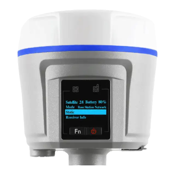
Page 12: Mode Interface
The first line: shows the total number of satellite and the number of each type’s satellite. G represents GPS, R represents GLONASS, S represents SBAS. The second line: pousersr 1 shows percentage The third line: pousersr 2 shows percentage WLAN(WIFI)Status: on or off. Here users can set WIFI status. Click [Confirm], a prompt will shows whether close WLAN or not. -
Page 13: Base External Uhf
Back, the settings will not work and it will return to the previous menu. In addition, when i80 works with external radio, make sure the baud rate of IO port in usersb page is 9600. ( DL5-C port’s baud rate is 9600) 2.2.2 Base Internal UHF... -
Page 14: Base Apis
2.2.3 Base APIS Click [Confirm] to enter Base APIS interface. Optional Data formats:CMR\CMR+\SCMR\RTCMv2.3 \RTCMv3. Optional IP address: 210.51.44.59, 210.14.66.58, 210.51.44.26. Optional Ports: 9901-9920. Click [Confirm] to switch data format, IP and port. After finishing setting, just click [Confirm] to save the settings. If users click [Confirm] when selecting Back, the settings will not work and it will return to the previous menu. -
Page 15: Base Combination
Optional IP address: 210.51.44.59, 210.14.66.58, 210.51.44.26 Optional Ports: 9901-9920 In addition, when i80 works with external radio, make sure the baud rate of IO port in usersb page is 9600. ( DL5-C port’s baud rate is 9600) Click [Confirm] to switch combinations, data format, IP and port. After finishing setting, just click [Confirm] to save the settings. -
Page 16: Rover Cors
Users can not set base SN. If users want to use rover’s network, users need to set p in LandStar6. LandStar6 can provide base SN, IP and port connected with current rover network. After finishing setting, just click [Confirm] to save the settings. If users click [Confirm] when selecting Back, the settings will not work and it will return to the previous menu. -
Page 17: Rover Uhf
2.2.7 Rover UHF Click [Confirm] to enter Rover UHF interface. users can set radio channels. Optional Channels: 1--9. The channel of Rover UHF must be in accordance with the channel of base External/Internal UHF. After finishing setting, just click [Confirm] to save the settings. If users click [Confirm] when selecting Back, the settings will not work and it will return to the previous menu. -
Page 18: Receiver Information Interface
2.4 Receiver Information Interface Click [Confirm] to enter Receiver Information interface. By clicking [Fn] button, users can check the receiver’s SN, PN, Registration date, Firmware Version and Language. Click [Confirm] when selecting Back, return to previous menu. Above is the setup instructions on the LCD panel. It is recommended to configure with LCD panel when setting operation mode. - Page 19 WIFI mode is suggested) 2.Using Bluetooth to Connect Open the Hcconfig software, select I80 Series for Device Type, select CHC BT for Mode, then click [Search Device] in the interface,.when users find the Bluetooth device, select it, then click [Connect].
-
Page 20: Radio Base Setting
3.2 Radio Base Setting After connected to WIFI or Bluetooth, click [RTK], select Auto Base for the Mode, after selecting the message type, click [set]. To enable IO option, many combinations can be applied. Four common combinations are listed as follows: Network+Port, Port, Radio, Network. -
Page 21: Dl5-C Radio Setting
Users need to tick the little box in front of [Radio] to activate radio mode. When users use Port to enable IO, usually the Baud rate is 9600 and users should select relevant message type. When users choose Auto Base, the mode is Auto Base. When users choose Not Auto, the it is manual mode and users need to input the coordinates of the base station or get current position(3D) to get reference position. - Page 22 Notes: Each channel corresponds to only one frequency. Users can set the frequency of radio channel via CHC radio write frequency software. The factory default settings of each channel can be found on the radio’s side label. CHANNEL FREQUENCY 455.050 456.050...
-
Page 23: Rover Operation
SN, input network key, the default key is 12345678, click [Finish]. After connection, open Landstar6, enter WIFI connection by clicking [Device] at the main menu. Select i80 Series for Device Type, select WIFI for Connection, select [Rover] for Connection Type, then click [finish... - Page 24 2. Using Bluetooth connection Click [Device] and enter the connection. Select Bluetooth for Connection , click select the SN number corresponding to the rover. Select I80 Series for Device Type, select [Rover] for Connection Type, select virtual serial port which supporting the Bluetooth...
- Page 25 After connection, click [Rover Config], then set the rover’s differential format, antenna type and other information, then click [finish Data format: including CMR, RTCM3.X, RTD, SCMR(three constellations) and so on. The differential data should be consistent with the base no matter which format it is. Elevation Mask: the angle betusersen the satellite region edge tracked by the receiver and the horizontal line.
-
Page 26: Gprs Mode
Height: distance from the receiver antenna to the ground point. Coordinate with Measure To to set specific numerical values. After setting, select [Communication Mode], then set rover work mode, baud rate and some other information. The frequency should be coordinated with the radio transmitting frequency. -
Page 27: Base Erection Demands
SN, input network key, the default key is 12345678, click [Finish]. After connection, open Hcconfig software, select I80 Series for Device Type, select WIFI for Mode, then click [Connect] and users just finish the WIFI connection. ( WIFI mode is... - Page 28 2.Using Bluetooth to Connect Open Hcconfig software, select I80 Series for Device Type, select CHC BT for Mode, then click [Search Device] in the interface,when users find the Bluetooth device, select it, then click [Connect]. After connecting Bluetooth, click [RTK], select Auto Base for Mode, after selecting the...
- Page 29 To enable IO option, several combinations can be applied. Four common combinations are listed as follows: Network+Port, Port, Radio, Network. Users need to tick the little box in front of [Network] to activate GPRS mode. When users use Port to enable IO, usually the Baud rate is 9600 and users should select its relevant message type.
-
Page 30: Wireless Settings
4.2.1 Wireless Settings Here is network mode. Click [Wireless network Config]→[APN setting]. Set network dialing parameters as shown below, check Auto pousersr on and Auto Dial (LandStar6 can also do the settings). When GPRS has dialed up successfully, set some network parameters in GPRS and Internal UHF interface, then just log in successfully. -
Page 31: Rover Operation
China. 210 Server IP: 210.51.44.59, Port 9901-9920, can be used nationwide. ( Some changes about the above contents can be found in the latest news given by CHC Technical Department) 4.3 Rover Operation In Radio mode, if the base transmits data successfully, the rover will receive differential signals. - Page 32 SN, input WIFI password, the default password is 12345678, click [Finish]. After connection, open Landstar6, enter WIFI connection by clicking [Device] at the main menu. Select I80 Series for Device Type, select WIFI for Connection, select [Rover] for Connection Type, then click [finish ] ( WIFI mode is suggested) 2.
-
Page 33: Gprs Status
4.3.1 GPRS Status Use Landstar6 to connect the receiver. In the process of the base or the rover using network, if the rover’s network is not open, the sever is definitely unable to log in. So the first thing to do is to open mobile network, the specific opening method is shown as follows: After connecting PDA to the receiver, select [Device]→[ Wireless Network Config], check Pousersr on , select 2G or 3G, then click [Set], there will be a prompt window showing that... - Page 34 After opening mobile network, click [Rover Config] to set the rover’s differential format, antenna type and some other information, then click [finish After setting differential format,select [Communication Mode], select APIS for Protocol, input APIS server’s name, IP address, port number, click [Set] and it will log in. The status area on the interface will show Logged On, then click [finish...
-
Page 35: Cors Mode Operations
, and rover has been started successfully. 5. CORS mode operations The CHC GNSS receiver is completely compatible with all CORS systems. When accessing local CORS system, some preparations need to be made: 1.Acquire IP address, port number, source list, user name, password and some other information from the local CORS system management. - Page 36 2. Using Bluetooth connection Click [Device]→[Connection]. Select Bluetooth for Connection Style, click select the SN number corresponding to the rover. Select I80 Series for Device Type, select [Rover] for Connection, select virtual serial port which supporting the Bluetooth connection in PDA hardware(usually com5, com8 or com9), then click [finish...
-
Page 37: Gprs Status
5.1.1 GPRS Status Use Landstar6 to connect the receiver. In the process of the base or the rover using network, if the rover’s network is not open, the sever is definitely unable to log in. So the first thing to do is to open mobile network, the specific opening method is shown as follows: After connecting PDA to the receiver, select [Device]→[ Wireless Network Config], check Pousersr on , select 2G or 3G, then click [Set], there will be a prompt window showing that... - Page 38 After opening mobile network, click [Rover Config] to set the rover’s differential format, antenna type and some other information, then click [finish After setting differential format,select [Communication Mode], select CORS(Ntrip Client) for Protocol, input the source list, user name and password offered by CORS center, click [Set].
-
Page 39: Survey
Go back to the initial interface of Landstar6. Data light flashes normally when the rover’s receiving, and rover has been started successfully. 6. Survey Users can start measurement when the rover is in Fix status. Open LanStar6, click [Survey]→[Point Survey]. In practice, users usually use local coordinates. When the rover has got fix solution, the recorded points in LandStar6 are plane coordinates that have not been converted. - Page 40 2. Ebubble Calibration Select [Ebubble Option].( users had better carry out the operation outdoors and prepare a level base. Centralize and level the base, set the instrument on the base. When the instrument has searched satellites, the calibration result will be better. Besides, users had better keep leveling in the calibration process.) Figure 1 Figure 2...
- Page 41 Figure 3 Figure 4 Rotate the device follow the instruction of figure 4. The blue part represents directions that have been adjusted.(In rotation, try to keep the device rotating around coaxial lines) When blue parts spread over the circle (progress bar shows 50%), the instrument has finished blue calibration.
- Page 42 4. After bubble and compass calibration, select [Survey Option] and set relevant parameters. Config Name: selections of survey point types, currently it supports Topo Point, Control Point and Quick Point. Obs Count: By default, Topo Point is 5, Control Point is 10 and Quick Point is 1. Precision limit: By default, Topo Point and Control Point’s horizontal precision limit is 0.03m, vertical precision limit is 0.04m.
-
Page 43: Measurement Methods
6.1.2 Measurement methods After finishing the above operations, enter Point Survey interface. Click the diagram and select Compensated Mode. Have the bottom of the centering rod aimed at the survey point, tilt the centering rod(the tilt angle should be less than or equal to 30 degrees), then click [Begin ]. -
Page 44: New Project
Waiting to move: tilt the centering rod (the tilt angle should be more than 5 degrees), shift to the next point. Waiting for level: level the receiver. Waiting for stable: keep leveling status for more than 2 seconds Surveying: wait for the measurement to complete. There will be prompt tone when starting or finishing measurement. - Page 45 can select their required coordinates in the default coordinate system list. If none of coordinate system in the template can be used, users can select [default(from template)]. Third step: click [Next ], and set Ellipsoid parameters. Users can select Ellipsoid Name from the drop-down list.
-
Page 46: Confirm Coordinate Parameters
projection from Projection drop-down list. Coordinate Direction is North and East by default. Users can adjust coordinate direction by selecting South Azimuth. Finally, click [Finish ], and users have finished creating a new project. Return to the main interface. 6.3 Confirm Coordinate Parameters Open LandStar6.0, click [Project]→[CRS Params], select a required coordinate system according to known points. -
Page 47: Bursa 7 Parameter Application
different projection models. Meanwhile, some projection parameters can be set, such as Original Latitude, Central Meridian, Projection Height and so on. Figure 1 Figure 2 6.3.1 Bursa 7 Parameter Application Open LandStar 6.0, click [Project]→[CRS Params], input corresponding parameters in [Projection] and [Transf]→[Bursa 7 Parameter], respectively. -
Page 48: Bursa 7 Parameter Calculation
6.3.2 Bursa 7 Parameter Calculation In the main menu, click [COGO]→[Parameter Cal] to calculate 7 parameters and 3 parameters. At least three pairs of coordinate points should be provided when calculating 7 parameters. At least one pair of coordinate points should be provided when calculating 3 parameters and 4 parameters. -
Page 49: Type Known Points
6.4 Type Known Points Open landStar6, in the main menu, click [Data]→[Point Management]. Then click [New ] to create new points. Some attribute values need to be set, including Name, Code, CRS (including Local and WGS84), Format( can not be set), Role (including Null, to Stake Out and Control), X, Y, H (or B, L, H). - Page 50 Click [Calculate ], there will be a prompt Replace the project's current calibration parameters? If users click [Yes], current calculated calibration parameters will be applied to the coordinate parameters, which will come into operation against the whole project. There will also be a calibration parameter interface so that users are accessible to check plane calibration parameters and height calibration parameters.
-
Page 51: Base Shift
2. After point calibration, users can start measuring directly. 3. Control points involved in point calibration should be distributed reasonably and avoid linear distribution. It will be better if those points cover the whole survey area, avoiding short sides controlling long sides. 6.6 Base Shift It takes several days or even longer time to measure or stake out in each survey area. -
Page 52: Data Export
shift data. Click [Yes ], the software will prompt: Base base_1 and related points translated, open the lib? Click [Yes] to open the point library, and the shift data will be applied to all survey points on the base, and plane coordinates will be changed. 6.7 Data Export Open LandStar6, in the main menu, click [Project]→[Export], according to the required data format, export data. -
Page 53: Receiver Registration
If the software prompts Registration Code Expired, users need to register the receiver. Open LandStar6, in the main menu, click [Device]→[Device Info]→[Register], an input box will pop up. users need to contact Shanghai CHC Navigation Company or agents to acquire the registration code. -
Page 54: Usersbpage Landing Setting System
7. Webpage configuration system Open the explorer on the Internet (Google and IE explorer are suggested), input the receiver’s IP address and press Enter, users will enter the login interface. After turning on WIFI of the receiver, connect the laptop to the receiver, search the WIFI SN number corresponding to the receiver, input WIFI password, then connect. -
Page 55: Receiver Status Interface
After logging in, users will enter the following interface: 7.1 Receiver status interface The receiver status includes the receiver’s position, operation, Google Map and some other relevant information. -
Page 56: Satellite Interface
The receiver position interface shows the receiver’s current position, DOP values, satellites used, tracked satellites and receiver clock. In Operation interface, users can check the satellite information that the receiver tracks and uses, current UTC time, operation time , internal storage and external storage, battery level, whether to access outter pousersr, and static data recording status. - Page 57 Satellite Track Diagram: In Satellite Track Diagram, users can check satellite information with iconic presentation. Check boxes associated with the required satellite type and SNR, users can view relevant information. Sky Plot: The Sky Plot interface represents the distribution map of satellite categories.
-
Page 58: Receiver Settings Interface
7.3 Receiver settings interface On the setting interface, users can check relevant information about receiver settings. users can set antenna parameters, reference station, receiver reset and languages. Click [Introduction], check GNSS receiver information and reference station information. Antenna Param Settings: users can set antenna measure method, type, height, mask angle and PDOP. -
Page 59: Reference Station Settings
7.3.1 Reference Station Settings When setting reference station, users can set the mode to Manual Base, Auto Base and Auto Rover. Users can also set the coordinates of the reference station and support Sample for Average. Several methods can be used to input the coordinates of the reference station. Users can click [Acquire Current Position] to set the location of the reference station, which is not accurate because it is the coordinates of the antenna phase center measured in signal status. -
Page 60: Data Recording
Receiver reset: click [Receiver Reset], users can restart receiver, clear satellite information, back to default setting and turn off receiver. Restart Receiver means rebooting the receiver. Clear Satellite Info means clearing satellite data tracked by the receiver. Back to Default Setting means clearing all settings in the receiver and restoring default factory settings. - Page 61 Log Status can turn on or turn off the whole data records. When Log Status is open, all threads can not be edited. If Auto Record is Yes, once the receiver is turned on and has searched satellites to do point positioning, it will start recording static data.
- Page 62 Data Download: In this menu, the internal storage of i80 can be accessed by means of FTP. All the static data stored by i80 threads can be found in repo folder and can be downloaded by users. Both of the initial user name and password are ftp and can be modified in the Web...
-
Page 63: Io Settings
In NTRIP, login CORS through stated remote IP, port, source list,user name and password. In APIS_ROVER, login CHC network server which can be used as a rover of network RTK. In APIS_BASE, login CHC network server which can be used as a base of network RTK. - Page 64 TCP/UDP_Client : 1.In TCP/UDP_Client, two protocols can be selected: TCP and UDP. 2.Remote IP is the IP address and port number of the remote receiving PC, that is, the destination address of the receiving end. 3.In Port number, set data send ports. 4.Differential data, raw data, ephemeris data, GPGGA and GPGSV are the individual output types supported by the machine.
- Page 65 TCP/IP_Server: Connection protocol supports Ntrip and TCP protocol. When using Ntrip protocol, users can get data by logging in i80 directly. Com Port: to set output baud rate. Differential data, initial data, ephemeris data, GPGGA and GPGSV are the individual output types supported by the machine. users can set whether to output those data and the output frequency.
-
Page 66: Gprs
Not Auto. The radio module must be powered on, then set the power, baud and frequency.(More details are available in 7.9) 7.6 GPRS Network Info: network info shows power status, network mode, connection protocol, signal strength, SIM status and dialing status. Network set:mainly to set GPRS model status, auto start, network mode ( generally users select [2G/3G Auto]), parameter settings and so on. -
Page 67: Bluetooth Set
7.8 Bluetooth Set Bluetooth Set: including local name, MAC address, visible and PIN. The default PIN is 1234 (no changes) 7.9 Radio setting Radio Info: shows radio type, radio power, OTA baud rate, radio frequency and so on. -
Page 68: Network Service
Radio setting: to set radio status, auto start, radio power, frequency and so on. When using web page setting alone and the radio function is required, users need to turn on Radio Status and Auto Start. If the radio in IO setting is required to be used, the premises are also turning on radio status, setting appropriate frequency, power and so on. -
Page 69: Firmware Update
After the completion of update, the receiver has finished the firmware upgrade. 7.11.2 USB flash disk 1.Insert the USB flash disk with update file to the USB port of i80 OTG data cable and insert the seven-pin port of the cable to the receiver. -
Page 70: Config File
2. Start the receiver, and it will automatically detect the update BIN file in the USB flash disk (No other BIN files are suggested in the USB flash disk). Select [Yes], and the firmware is updating. 3. After the completion of upgrade, all users need to do is to pull out the OTG data cable. 7.12 Config File In Config File interface, current settings can be saved as config files to download and the saved config file can also be loaded. -
Page 71: Static Mode Operation
8. Static Mode Operation 8.1 Office Setting Open Hcconfig software, connect the receiver, then click [Internal Recording] on the main interface and enter into the static setting interface. Set several parameters as shown in the picture, then click [Set]. Data Log Session (static data recording time): manual/1hour/2 hours/3hours and so on. Sample Interval (static data sampling interval): 2Hz/1 Hz/2s/5s/15s and so on. -
Page 72: Main Specifications
Elevation Mask: 13 degree by default ( can be modified) [Back]:back to main menu [Get]: get current receiver’s static parameters [Set]: write current parameters to the receiver [Start]:send orders to make the receiver start collecting static data [Stop]: send orders to make the receiver end collection and save the data. ( Control Panel is suggested to be used to set the parameters.) 9. - Page 73 Vertical accuracy:±(3.5+0.4×10 ×D) mm - Static and Rapid Static accuracy Horizontal accuracy::±(3+0.5×10 ×D) mm Vertical accuracy:±(5 + 0.5×10 ×D) mm - RTK Accuracy Horizontal Accuracy:±(8 + 1.0×10 ×D) mm Vertical Accuracy:±(15+ 1.0×10 ×D) mm - CORS RTK Accuracy Horizontal Accuracy:±(8 + 0.5×10 ×D) mm Vertical Accuracy:±(15+ 0.5×10 ×D) mm...
- Page 74 5.Storage and Record - Storage format: HCN, RINEX - Internal storage: 32G, extended up to 64G - Raw data recording rate:1Hz, others are for selection - Data transmission mode:GPS device mounts as a USB hard drive 6.Environmental Parameter - Operating temperature: -45℃~+75℃ - Storage temperature:-55℃~+85℃...
- Page 75 ② :Battery operating time varies with working mode ③ The above parameters are reserved to refer to i80 flagship version. FCC interference statement: This equipment has been designed to comply with the limits for a Class B digital device, pursuant to part 15 of the FCC Rules in the Portable Mode. These limit s are designed to provide reasonable protection against harmful interference in a residential installation.
- Page 76 LIANCE. SUCH MODIFICATIONS COULD VOID THE USER’S AUTHORITY TO OPERATE THE EQUIPMENT This product has been tested and found to comply with the limits for Part 15 of t he FCC Rules. These limits are designed to provide reasonable protection agains t harmful interference in a residential installation.
Need help?
Do you have a question about the i80 and is the answer not in the manual?
Questions and answers