CHC i80 User Manual
Gnss
Hide thumbs
Also See for i80:
- User manual (76 pages) ,
- Quick start manual (28 pages) ,
- Maintenance manual (13 pages)
Table of Contents
Advertisement
Quick Links
Download this manual
See also:
Quick Manual
Advertisement
Table of Contents

Subscribe to Our Youtube Channel
Related Manuals for CHC i80


Summary of Contents for CHC i80
- Page 1 Safety Information CHC® i80 GNSS Receiver Revision 1.0 May 2015...
- Page 2 Operation is subject to the following two conditions: (1) this device may not cause harmful interference and (2) this device must accept any interference received, including interference that may cause undesired operation. i80 GNSS Receiver User Guide – Revision 1.0 May 2015 Written by January LEE...
-
Page 3: Table Of Contents
1.1.3. Use and Care .......................... 5 1.2. Technical support ..........................5 1.3. Disclaimer ............................5 1.4. Your comments ..........................5 2. Getting started with i80 ..........................6 2.1. About the receiver ..........................6 2.2. Parts of the receiver.......................... 6 2.2.1. Front panel ..........................6 2.2.2. - Page 4 7.3.2. Antenna Param Settings submenu ..................80 7.3.3. Reference Station Settings submenu ................... 81 7.3.4. Receiver Reset submenu ...................... 82 7.3.5. Languages submenu ......................83 7.4. Data Recording menu ........................83 7.4.1. Log Settings submenu ......................83 i80 GNSS Receiver User Guide Page...
- Page 5 7.11.5. GNSS Registration submenu ....................98 7.11.6. The Hardware Version submenu ..................98 A. Communication ports definition ......................100 A.I. CHC i80 receiver IO port (7-pin Lemo port) definition ..............100 A.II. CHC i80 receiver USB port (7-pin Lemo port) definition .............. 100 ...
-
Page 6: Introduction
1. I NTRODUCTION The i80 GNSS Receiver User Guide describes how to set up and use the CHC® i80 GNSS receiver. In this manual, “the receiver” refers to the i80 GNSS receiver unless otherwise stated. Even if you have used other Global Navigation Satellite Systems (GNSS) products before, CHC recommends that you spend some time reading this manual to learn about the special features of this product. -
Page 7: Use And Care
If you have a problem and cannot find the information you need in this manual or CHC website (www.chcnav.com), contact your local CHC dealer from which you purchased the receiver(s). If you need to contact CHC technical support, please contact us by email (support@chcnav.com) or Skype (chc_support). 1.3. D... -
Page 8: Getting Started With I80
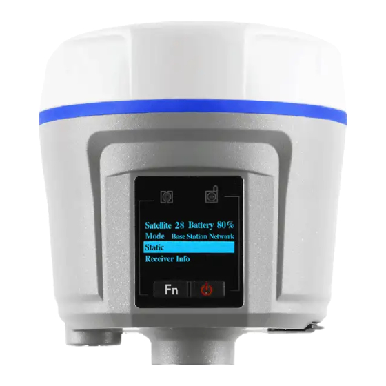
Bluetooth and Wi-Fi technology provide cable-free communication between the receiver and controller. The receiver can be used as the part of a RTK GNSS system with CHC LansStar6 software. And you can download the GNSS data that recorded in the internal memory of receiver to a computer. - Page 9 2. Getting started with i80 Satellite LED Correction LED LCD screen Power & Enter Fn button button Name Description Satellite LED (Blue) Shows the number of satellites that the receiver has tracked. When the receiver is searching satellites, the blue LED flashes once every 5 seconds.
-
Page 10: Lower Housing
2. Getting started with i80 continuously to reset the mainboard. For more information about the front panel and relevant operations, see Front panel operation. 2.2.2. L OWER HOUSING The lower housing contains one SIM card slot, two battery compartments, one TNC radio antenna connector, two communication and power ports, one 5/8-11 threaded insert, and two nameplates. -
Page 11: Batteries And Power
Discontinue charging a battery that gives off extreme heat or a burning odor. • Use the battery only in CHC equipment that is specified to use it. • Use the battery only for its intended use and according to the instructions in the product documentation. -
Page 12: 2.3.1.2. Battery Safe
2. Getting started with i80 2.3.1.2. Battery safe WARNING - Do not damage the rechargeable Lithium-ion battery. A damaged battery can cause an explosion or fire, and can result in personal injury and/or property damage. To prevent injury or damage: •... -
Page 13: Inserting Battery And Sim Card
2. Getting started with i80 In the field: The external power cable is connecting with a vehicle battery, the output port of the external power cable connects with the Power Port of the GPS to PC Data Cable/USB Cable. WARNING - Use caution when connecting external power cable's clip leads to a vehicle battery. -
Page 14: Product Basic Supply Accessories
2. Getting started with i80 Push down Battery cover Battery bail Insert the SIM card with the contacts facing upward, as indicated by the SIM card icon next to the SIM card slot. To eject the SIM card, slightly push it in to trigger the spring-loaded release mechanism. -
Page 15: Rover Kit Basic Supply
2. Getting started with i80 GPS to PC Data Cable Lithium Battery H.I. Tape Extension pole Tribrach with optical plummet Auxiliary H.I. Tool Tribrach adaptor Transport Hard Case 2.5.2. R OVER KIT BASIC SUPPLY Item Picture i80 GNSS Receiver UHF Bar Antenna (450-470 MHz) OTG Cable ... -
Page 16: Connecting To An Office Computer
2. Getting started with i80 USB Cable GPS to PC Data Cable Battery Charger Power Adapter with Cord Lithium Battery 2M Range Pole w/bag Auxiliary H.I. Tool Transport Hard Case 2.6. C ONNECTING TO AN OFFICE COMPUTER The receiver can be connected to an office computer for serial data transfer or settings via a GPS to PC Data Cable. -
Page 17: Connecting To A Controller
1. Turn on the controller → run Hcconfig → tap Connection in the main menu. 2. In the Connection screen, select CHC for the Manufacture field, Smart GNSS for Device Type field, WIFI for Mode field. 3. Tap the setting button next to Mode field → turn on the Wi-Fi function →... - Page 18 2. Getting started with i80 Tip – The Wi-Fi key of the receiver is 12345678 by default. 6. Tap Finish button in the pop-up screen, and then you can check that the controller system has connected to the Wi-Fi of the receiver. Tap ok button in the top right corner.
-
Page 19: Connecting Via Bluetooth With Hcconfig Software
1. Turn on the controller → run Hcconfig → tap Connection in the main menu. 2. In the Connection screen, select CHC for the Manufacture field, Smart GNSS for Device Type field, Sys. BT for Mode field. 3. Tap the setting button next to Mode field → turn on the Bluetooth function →... - Page 20 2. Getting started with i80 In the Select a Bluetooth screen, tap the Bluetooth device named as the SN of your receiver → tap Next button. 5. In the Enter Passcode screen, enter the Passcode → tap Next button. After the device is added, tap Done button.
-
Page 21: 2.7.2.2. Via Chc Bluetooth
2. In the Connection screen, select CHC for the Manufacture field, Smart GNSS for Device Type field, CHC BT for Mode field, COM Port that you want to be used to connect the controller with the receiver for the Port field. -
Page 22: Connecting Via Wi-Fi With Landstar 6 Software
2. Getting started with i80 3. Tap Search Device to search the Bluetooth devices → tap the Bluetooth device named as the SN of your receiver → tap Connect button to connect the software with the receiver via CHC Bluetooth. 2.7.3. C ONNECTING VIA... - Page 23 6. In the Main Menu, tap Device →tap Connection. 7. Select CHC for the Manufacture field, Smart GNSS for Device Type field, WIFI for Connect field, CHCi80 for Antenna Type field → select Base or ...
-
Page 24: Connecting Via Bluetooth With Landstar 6 Software
1. Turn on the controller →run LandStar 6 → create a new project or open an existing project. 2. In the Main Menu, tap Device → tap Connection. 3. Select CHC for the Manufacture field, Smart GNSS for Device Type field, Bluetooth for Connection field. 4. Tap icon next to Connection field →... -
Page 25: Connecting To A Usb Drive
2. Getting started with i80 back to Connection screen. 5. Select COM Port that you want to be used to connect the controller with the receiver for the Port field → CHCi80 for Antenna Type field → select Base or Rover as Connection Type according to the your needs →... -
Page 26: For Data Logging
2. Getting started with i80 2.8.1. F OR DATA LOGGING The receiver can log data directly to a USB drive; however, the logged (existing) data cannot be downloaded directly from the receiver memory to a USB drive. To log data directly to a USB drive: 1. -
Page 27: For Firmware Upgrade
Data logging using receivers requires access to suitable GNSS postprocessing software such as the CHC Geomatics Office (CGO) Software. The following figure shows how to connect to the computer for downloading logged data: ... - Page 28 3. Double click the folder that you has configured to store the static data, you will see the folder(s) created by the i80 system automatically and named by the date which is decide by GPS time when you start to log data.
-
Page 29: Front Panel Operation
“Dial Status Online”. Cancel Click Enter button to back to the top-level menu. Mode Rover UHF Click Enter button to enter the i80 GNSS Receiver User Guide Page... - Page 30 Click Enter button to save the settings of the data logging and back to the top-level menu, and then the settings will take effect. i80 GNSS Receiver User Guide Page 28...
-
Page 31: Configure The Working Mode
Click Enter button to cancel the settings and back to the second-level menu. Base Int. UHF Set up the receiver as a base station using internal UHF. Click Enter button to enter the configuration screen. i80 GNSS Receiver User Guide Page 29... - Page 32 Fn button to move to Cancel field and click Enter button to cancel the change and back to the i80 GNSS Receiver User Guide Page 30...
- Page 33 Click Enter button to save the settings and back to the top-level menu, and then this combination working mode will take effect. Cancel Click Enter button to cancel the settings and back to the second-level menu. i80 GNSS Receiver User Guide Page 31...
- Page 34 Cancel Click Enter button to cancel the settings and back to the second-level menu. Rover Ntrip/IP Set up the receiver as a rover station using i80 GNSS Receiver User Guide Page 32...
- Page 35 Note – The operation menus of front panel may vary from different firmware versions of your receiver. The menus described in this chapter are based on firmware version 1.1.16. i80 GNSS Receiver User Guide Page 33...
-
Page 36: Base Station Setup And Operation
Do not locate a GNSS receiver, GNSS antenna, or radio antenna within 400 meters (about 1,300 feet) of transmitters, such as a power radar or i80 GNSS Receiver User Guide Page... -
Page 37: Outputting Corrections Using Internal Radio Modem
UTPUTTING CORRECTIONS USING INTERNAL RADIO MODEM 4.2.1. B ASE STATION SETUP 1. Connect the radio antenna onto i80 receiver. Screw the receiver onto extension pole. 2. Screw the extension pole with auxiliary H.I. tool onto tribrach adaptor. 3. Mount the tribrach onto the tripod. -
Page 38: Configuring The Base Station
11. Tap Set button to save the settings → tap Back button to go back to main menu →tap Exit → select Exit Software Only option to exit Hcconfig. When select Manual Base for Mode field: i80 GNSS Receiver User Guide Page 36... -
Page 39: 4.2.2.2. Configuring Via Landstar 6 Software
(control) point to the bottom of receiver for Height field. 9. Configure the coordinates of base station. There are three methods available to configure the base station coordinates: a) Tap next to Name field to select an existing point. i80 GNSS Receiver User Guide Page 37... -
Page 40: Outputting Corrections Using External Radio
(control) point to the auxiliary H.I. tool, the CHC LandStar 6 will calculate the height to the Antenna Phase Center (APC) automatically. -
Page 41: Configuring The Base Station
3. After successful connection, tap RTK in the main menu. 4. In RTK screen, select Mode from the dropdown list. When select Auto Base for Mode field: 5. Configure the related parameters: Format, Baud, Elevation and PDOP. i80 GNSS Receiver User Guide Page 39... -
Page 42: 4.3.2.2. Configuring Via Landstar 6 Software
Height field: enter the vertical height (in meters) you calculated from the known (control) point to the bottom of receiver for Height field. 7. Configure the coordinates of base station. There are three methods available to configure the base station i80 GNSS Receiver User Guide Page 40... - Page 43 LandStar 6 will disconnect with the receiver automatically. 10. After the receiver is successfully transmitting correction data (with the green LED flashing once per second), power on the external radio, and then configure the external radio from its panel. i80 GNSS Receiver User Guide Page 41...
-
Page 44: Rover Station Setup And Operation
The system needs five common satellites to provide RTK positioning. WARNING – Take care not to touch overhead power lines with the CHC i80 GNSS receiver or the range pole when moving the equipment into position. -
Page 45: Rover Station Setup
5.2. R OVER STATION SETUP 1. If required, connect the radio antenna onto i80 receiver. 2. Screw the receiver on top of the range pole. 3. Fix the controller bracket on the range pole. 4. Fit the controller in the controller bracket. - Page 46 1 to 9 is predefined; however, the frequency of channel 0 is editable. Baud field: select the baud rate the same as that of base station. Power field: select the power from the dropdown list according to your i80 GNSS Receiver User Guide Page 44...
-
Page 47: Receiving Corrections Using Internal Cellular Modem
1. Insert a SIM card into SIM card slot of the receiver (please see 2.4. Inserting battery and SIM card for instruction) and the power on the receiver. 2. Turn on the controller → run LandStar 6 → create a new project or open i80 GNSS Receiver User Guide Page 45... - Page 48 IP Addr field: enter the IP address and the Port with the soft keyboard, or tap next to this field to select the predefined service. Source field: tap next to this field to get the source table list, and i80 GNSS Receiver User Guide Page 46...
- Page 49 Device screen. 11. Users can conduct surveying work after the rover receiver receives correction data (with correction LED flashes once per second) and gets fixed solution. i80 GNSS Receiver User Guide Page 47...
-
Page 50: Receiving Corrections Using Cellular Modem In The Controller
Height field: enter the height (in meters) of the range pole you are using. 7. If required, tick Warning when base changed option → tap in the lower right corner to save the settings and go back to Device screen. i80 GNSS Receiver User Guide Page 48... - Page 51 User Name field: enter the user name of the network (such as NTRIP network), if required. Password field: enter the user name of the network (such as NTRIP network), if required. 10. Tap to log-in the network service. i80 GNSS Receiver User Guide Page 49...
- Page 52 (with correction LED flashes once per second) and gets fixed solution. Note – Before switch to other communication mode, please tap Communication Mode screen to break the connection to the network. i80 GNSS Receiver User Guide Page 50...
-
Page 53: Survey With Landstar 6 Software
6. S URVEY WITH SOFTWARE The CHC Landstar 6 Software (“LandStar 6”) is a field survey software which developed based on more than ten years of development experience of CHC and feedback of surveyors from different fields of application. LandStar 6... - Page 54 (from template) if there is no suitable template, and then tap button. 4. Confirm the ellipsoid information or select one ellipsoid from the dropdown list for Name field, and then tap button. i80 GNSS Receiver User Guide Page 52...
- Page 55 Note – To configure the parameters for Bursa 7 Parameter option and Molodensky 3 Parameter option, users need to tap button to unlock the editing function. Tip – The default login values of editing function are “admin” for Name and i80 GNSS Receiver User Guide Page 53...
-
Page 56: Key In Points
1. In the main menu, tap Data → tap Point Management. 2. Tap button in the lower left corner of Point Data Management screen, and then configure the related parameters of the new point as follows: Name field: enter the point name. i80 GNSS Receiver User Guide Page 54... -
Page 57: Measure Points
If necessary, enter the feature code in the input frame on the top right corner. button to select a measurement mode in the pop-up window. Notes Users can tap button to configure the settings of each i80 GNSS Receiver User Guide Page 55... - Page 58 Point Survey screen. button, hold the range pole until the countdown timer disappears, and then move to next point to continue. When tick Auto measure in the Survey Option screen: i80 GNSS Receiver User Guide Page 56...
- Page 59 → tilt the range pole (exceeding the specified tilt tolerance). A “Waiting for level” message appears over the eBubble → move the receiver to the target measuring point → level the range pole. i80 GNSS Receiver User Guide Page 57...
-
Page 60: Survey With Tilt Sensor
6.3.2. S URVEY WITH TILT SENSOR The i80 receiver is integrated with tilt sensor, which allows the use of eBubble (electronic bubble) and tilt compensation. The tilt compensation allows the collection of points even when the receiver is tilted up to 30 degrees off plumb. -
Page 61: 6.3.2.1. Calibrating The Tilt Sensor
The integrated tilt sensor calibration is performed within the CHC LandStar 6 software. To calibrate the integrated tilt sensor, place the receiver on a stable range pole or tripod with tribrach. - Page 62 → tap Yes button. Perform the calibration according to the graphic displayed on the screen. Once the calibration is complete, tap button in the lower right i80 GNSS Receiver User Guide Page 60...
-
Page 63: 6.3.2.2. Measure Points In Compensated Mode
Compensated Mode in the pop-up Survey Option screen. The auto measure function is available for the Compensated Mode. When untick Auto measure in the Survey Option screen: i80 GNSS Receiver User Guide Page 61... - Page 64 30 degrees; however, yellow or green means the tilt is within 30 degrees or 24 degrees. When tick Auto measure in the Survey Option screen: i80 GNSS Receiver User Guide Page 62...
- Page 65 → tilt the range pole to more than 30 degrees. 15. A “Waiting for level” message appears over the eBubble → move the receiver to the target measuring point → tilt the range pole within 30 degrees. i80 GNSS Receiver User Guide Page 63...
-
Page 66: Point Adjust (Site Calibration)
Point adjust, also known as “site calibration”, is used to transform WGS-84 coordinates into local grid coordinates. Notes General speaking, if a three- or seven-parameter datum transformation has been configured for project, users can skip the i80 GNSS Receiver User Guide Page 64... - Page 67 Select the adjustment method from the dropdown list next to Method field. i80 GNSS Receiver User Guide Page 65...
- Page 68 1. The “Fixed difference” fit method is used when the measuring surface is almost horizontal, and it requires at least 1 point pair with elevation information to be involved in the computation. i80 GNSS Receiver User Guide Page 66...
- Page 69 Note – For best results, make sure that the control points are evenly distributed to the extent of the job area. 11. Tap button → a message will pop up asking user whether to replace parameters of current project. i80 GNSS Receiver User Guide Page 67...
- Page 70 Plane Adjust tab and Height Adjust tab. Note – To check the horizontal and vertical adjustments in Plane Adjust tab and Height Adjust tab, users need to tap button to unlock the display function first. i80 GNSS Receiver User Guide Page 68...
-
Page 71: Base Shift
However, coordinates determined by the base station that set up on an autonomous point should be carried out a base shift, which provided by CHC LandStar 6 software, to keep their base station coordinate the same as the initial coordinate system. - Page 72 If tap YES button, all the coordinates determined by the current base coordinate system will be translated. Also, the Point Data Management screen will pop up to help user check whether the coordinates determined by the current base coordinate system have changed. i80 GNSS Receiver User Guide Page 70...
-
Page 73: Data Export
Tick the point type(s) → enter the File Name → select the File Type from the dropdown list → select the path that used to store the file. button → the software will prompt whether the file has been successfully exported. i80 GNSS Receiver User Guide Page 71... -
Page 74: Receiver Registration
6.7. R ECEIVER REGISTRATION When the software prompt that the receiver is overdue, users need to contact your local CHC dealer to get the registration code. To register the receiver: In the main menu, tap Device → tap Device Info. - Page 75 6. Survey with LandStar 6 software Tap Finish button to complete the registration, and then the software will show the expire date. i80 GNSS Receiver User Guide Page 73...
-
Page 76: Configuring Through A Web Browser
Note – Tick remember me option, and then the browser will remember the Login Account and Password you entered for the next time you enter this login screen. 5. Once you are logged in, the web page appears as follows: i80 GNSS Receiver User Guide Page... -
Page 77: Status Menu
Currently, three languages are available: 7.1. S TATUS MENU This menu provides a quick link to review the receiver's position information, satellites tracked, runtime, current data log status, current outputs, available memory, and more. i80 GNSS Receiver User Guide Page 75... -
Page 78: Position Submenu
With this information, it is easy to tell exactly what functions the receiver is performing: i80 GNSS Receiver User Guide Page 76... -
Page 79: Google Map Submenu
7. Configuring through a web browser 7.1.3. G OOGLE AP SUBMENU Tap this submenu to show the location of the receiver on Google map. i80 GNSS Receiver User Guide Page 77... -
Page 80: Satellites Menu
IAGRAM SUBMENU The following figure is an example of satellite track diagram page. Users can determine the satellite types and the corresponding SNR of L-band carriers to be displayed in any combination. i80 GNSS Receiver User Guide Page 78... -
Page 81: Skyplot Submenu
7.3. R ECEIVER ETTINGS MENU Use this menu to configure settings such as the antenna type and height, elevation mask and PDOP setting, the reference station coordinates, receiver resetting and web interface language: i80 GNSS Receiver User Guide Page 79... -
Page 82: Introduction Submenu
Use this screen to configure all of the items relating to the GNSS antenna. You must enter the correct values for all antenna-related fields, as the choices you make significantly affect the accuracy for logged data and broadcast correction data: i80 GNSS Receiver User Guide Page 80... -
Page 83: Reference Station Settings Submenu
There are three modes available: a) Auto Rover: The receiver will serve as a rover after this mode is enabled, and then receive correction data through the working mode set last time. i80 GNSS Receiver User Guide Page 81... -
Page 84: Receiver Reset Submenu
→ the result will be served as the coordinate of current positon. If users need to save the changes, please tap button. 7.3.4. R ECEIVER ESET SUBMENU Use this screen to completely or partially reset the receiver: i80 GNSS Receiver User Guide Page 82... -
Page 85: Languages Submenu
Shows the data logging status, internal and external storage usage and data logging status of each session. Also, users can configure the data logging settings for each session, including recording name, store location, storage limit, store formats, start time, etc. i80 GNSS Receiver User Guide Page 83... - Page 86 The parameters are mainly as follows: Recording Name: The name of this logging session. Sample Interval: Select the observable rate from the dropdown list. Store Location: Determine whether to store at internal storage or i80 GNSS Receiver User Guide Page 84...
-
Page 87: Ftp Push Settings Submenu
Only files that are configured to use FTP push are transmitted. Tap Modify button to the right of the required FTP server and the FTP Push Settings screen appears: i80 GNSS Receiver User Guide Page 85... -
Page 88: Ftp Push Recording Submenu
The default logon account for the internal FTP site is: User name: ftp Password: ftp 2. Click the directory named as “repo” to view and download the files currently stored on the receiver: i80 GNSS Receiver User Guide Page 86... -
Page 89: Io Settings Menu
CMR, RTCM, Raw data, Ephemeris data, GPGGA, GPGSV, on TCP/IP, UDP, serial port, or Bluetooth ports. 7.5.1. IO S ETTINGS SUBMENU The following figure shows an example of the screen that appears when you select this submenu. i80 GNSS Receiver User Guide Page 87... - Page 90 NTRIP, APIS_BASE and APIS_ROVER → configure the related parameters → click log on CORS or APIS. Connection Protocol: NTRIP Connection Protocol: APIS_BASE i80 GNSS Receiver User Guide Page 88...
- Page 91 UDP → enter the IP and Port of the target server → configure messages that you want to output to the target server → click to save and complete the connection. i80 GNSS Receiver User Guide Page 89...
- Page 92 IO Settings screen will appear → select one of the connection protocols between NTRIP and TCP → configure the other related parameters → click to save the settings and open the server. Connection Protocol: NTRIP Connection Protocol: TCP 4. COM Port i80 GNSS Receiver User Guide Page 90...
- Page 93 6. Radio Tap the Settings button to the right of Radio → the Radio Settings screen will appear → select the format of differential data that you want to transmit i80 GNSS Receiver User Guide Page 91...
-
Page 94: Gprs Menu
The following figure shows an example of the screen that appears when you select this submenu: 7.6.2. N ETWORK ET SUBMENU Use this submenu to configure network settings, including GPRS model status, network mode, dialing status, APN, etc. i80 GNSS Receiver User Guide Page 92... -
Page 95: Wifi Menu
IFI MENU Use this menu to check and configure the Wifi settings: 7.7.1. W NFO SUBMENU The following figure shows an example of the screen that appears when you select this submenu: i80 GNSS Receiver User Guide Page 93... -
Page 96: Wifi Settings Submenu
The following figure shows an example of the screen that appears when you select this submenu: 7.9. R ADIO ETTINGS MENU Use this menu to check and configure radio related settings, including protocol, OTA baud rate, frequency, etc. i80 GNSS Receiver User Guide Page 94... -
Page 97: Radio Info Submenu
Use this submenu to configure radio settings, including radio status, whether to switch on auto start or not, protocol, transmitting power, radio frequency, etc. 7.10. N ETWORK ERVICE MENU Use this menu to configure the receiver’s HTTP port, and the username and i80 GNSS Receiver User Guide Page 95... -
Page 98: Http Submenu
7.11. F IRMWARE MENU Use this menu to check the current firmware information, download the system log, update the receiver firmware, download or update the configuration file and register the receiver, and more: i80 GNSS Receiver User Guide Page 96... -
Page 99: Firmware Info Submenu
Use this submenu to load new firmware to the receiver across the network. Tap the Browse button to locate the upgrade file → tap Confirm button to confirm the selected upgrading file and start upgrading. i80 GNSS Receiver User Guide Page 97... -
Page 100: Config File Submenu
Registration Code field → tap Registration button to complete the registration. 7.11.6. T ARDWARE ERSION SUBMENU Use this submenu to check the hardware information, including main board version and core board version: i80 GNSS Receiver User Guide Page 98... - Page 101 7. Configuring through a web browser i80 GNSS Receiver User Guide Page 99...
-
Page 102: Communication Ports Definition
Ground ( - ) Ground ( - ) RS232-TX (Output) Not Used Not Used RS232-RX (Input) A.II. CHC RECEIVER PORT EMO PORT DEFINITION FUNCTION Ground ( - ) Ground ( - ) VBUS i80 GNSS Receiver User Guide Page... - Page 103 CHC - Shanghai HuaCe Navigation Technology Ltd. Building C, NO. 599 Gaojing Road, Qingpu District, 201702 Shanghai, China Tel: +86 21 542 60 273 Fax: +86 21 649 50 963 Email: sales@chcnav.com support@chcnav.com Website: www.chcnav.com i80 GNSS Receiver User Guide...
Need help?
Do you have a question about the i80 and is the answer not in the manual?
Questions and answers