Table of Contents
Advertisement
Quick Links
Advertisement
Table of Contents

Subscribe to Our Youtube Channel
Related Manuals for CHC P3E


Summary of Contents for CHC P3E
- Page 1 P3E| ETTING TARTED UIDE PPLICATIONS GNSS RECEIVER ULTI ...
- Page 2 Copyright Copyright 2009‐2012 CHC | Shanghai Huace Navigation Technology Ltd. All rights reserved. The CHC are trademark of Shanghai Huace Navigation Technology Limited. All other trademarks are the property of their respective owners. Trademarks All products and brand names mentioned in this ...
-
Page 3: Table Of Contents
Use and Care ........................ 2 Overview ............................ 2 2.1. Features .......................... 2 2.2. Specifications ........................ 2 2.3. P3E Basic Supply ........................ 4 P3E DESCRIPTION.......................... 5 3.1. Receiver Front View ...................... 5 Software installation......................5 3.2. CHC Software overview . ..................5 3.2.1. ... -
Page 4: Introduction
1.5. R EGULATIONS AND AFETY The P3E Sensor may be delivered with optional internal data links. Regulations regarding the use of the data link vary greatly from country to country. Depending on local authorities, the P3E can be used without obtaining an end‐user license or may require administrative permissions. For license information, consult your local dealer. ... -
Page 5: Use And Care
1.6. U SE AND The P3E Sensor is designed to withstand the rough environment that typically occurs in the field. However, the P3E Sensor is high‐precision electronic equipment and should be treated with reasonable care. 2. O VERVIEW 2.1. F EATURES Designed for seamless integration, the P3E is a powerful ... - Page 6 ∙ Vertical: 15 mm + 1 ppm RMS ∙ Initialization time: typically < 10 s ∙ Initialization reliability: typically > 99.9% • Post Processing Static ∙ Horizontal: 3mm + 0.5ppm RMS ∙ Vertical: 5mm + 0.5ppm RMS ∙ Baseline Length: ≤ 300 km Communications • 1x LAN port: ∙ 1 port with RJ45 connector supports links to 10BaseT/100BaseT networks. ∙ HTTP, HTTPS, TCP/IP, UDP, NTRIP Caster, NTRIP Server, NTRIP Client ∙ Proxy server support ∙...
-
Page 7: P3E Basic Supply
User Interface • PC Control Utility via Serial • Web User Interface ∙ Secure ∙ Allows remote configuration, data retrieval and firmware updates ∙ Setup of multiple streaming / monitoring ports Antenna option • A220GR GNSS Geodetic Antenna, and C220GR GNSSChoke Ring Antenna (1)Accuracy and reliability specifications may be affected by multipath, satellite geometry and atmospheric conditions. Performances assume minimum of 5 sat ellites,follow up of recommended general GPS practices. (2) Feature available on demand Specifications are subject to change without notice. 2.3. P3E ASIC UPPLY The table below provides an overview of the different items composing the P3E Base Kit Item CHC P3EGNSS Receiver Power Adapter with Cord Transport Case Whip antenna GPS to PC Data Cable Page 4 ... -
Page 8: P3E Description
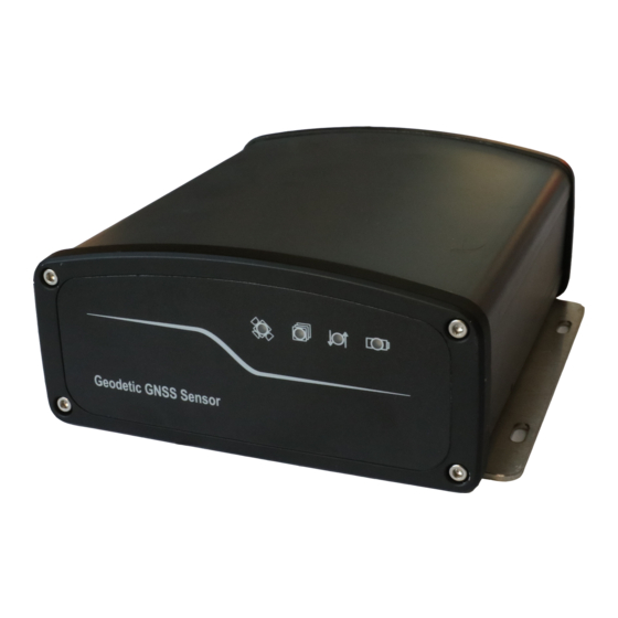
2M Internet Cable 3. P3E DESCRIPTION 3.1. R ECEIVER RONT Power LED Switch button Satellites LED • Power Button 10 Pin Lemo Serial Port 1 Use this port to connect the P3E CHC to PC or PDA and also to supplypower to receiver via the CHC Data Cable. Refer to Appendix A for the LEMO pin out diagram. GPS Antenna Connector The TNC GPS antenna connector allows connection of the external GNSS antenna to the P3EGNSS. 3.2. S OFTWARE INSTALLATION 3.2.1 CHC ... -
Page 9: Powering The P3E
CAUTION: To validate the Setting you need to turn the P3E receiver OFF and then ON. • HCGPRSCe Radio and built‐in GPRS module setup. • RTKCe / LandstarSoftware to perform RTK Surveying Data collection (requires activation). 3.2.2 I SOFTWARE NSTALLING The P3E software RTKCe, HCGPSSet and HCGPRSCe are bundled in one combined CAB format installation package. To install, copy the installation file to your PDAor PC and double click the on the CAB file. The software installation process starts automatically. CAUTION: Use only the latest CHC software CAB file with the P3E 3.3. P P3E OWERING THE P3E can be powered by either connecting it to the mains power (A.) or to an external battery (B.) A. Connect to the mains power use CHC GPS to PC cable + Power Adapter ... -
Page 10: System Installation
3.4. S YSTE NSTALLATION 3.4.1 S GNSS UPPORTED ANTENNAS CHC recommends the use of the CHC A220GR GNSS Antenna or CHC C220GR GNSS Choke Ring with the P3E GNSS Receive Other GNSS antennas may however be used ensuring that the antenna receive the proper GNSS frequencies and operates at either 3.3V or 7.1V with a signal greater than 40 dB at the antenna port. 3.4.2 I NSTALLING THE NTENNAS Choosing the correct location for the GNSS antenna is critical to the installation. Poor or incorrect placement of the antenna can influence accuracy and reliability and may result in degraded performances normal operation. ... -
Page 11: P3E Connection Diagram
™ by ONFIGURATION OF LASH Go to the follow link to download the BD9xx WinFlash V234_V462.exesoftware: Install WinFlash on your PC Connect the P3E to your PC using the GPS to PC Data cable by serial port 5.1.1 Upgrading the receiver firmware Start the WinFlash utility. The Device Configuration screen appears. From the PC serial port field, select the serial (COM) port on the computer that the receiver is connected to Page 8 ... - Page 12 Click Next Select Load GPS software and then click Next. From the Available Software list, select the latest version and then click Next. If all is correct, click Finish, then Click OK. The Software Upgrade window appears again and states that the operation was completed successfully. Page 9 ...
- Page 13 5.1.2 IP configuration Start WinFlash and follow the instruction below to set the static IP of N71 sensor to log on internet. Page 10 ...
-
Page 14: Configuration Of P3E Output Adress With Tool Box
Not all receiver functions are supported in the Configuration Toolbox software. The Configuration Toolbox is the only utility that can be used to load local datums and coordinate systems into the receiver. Go to the follow link to download the software Install ToolBox on your PC Connect the P3E to your PC using the GPS to PC Data cable The instructions below describes the setup of NMEA output on serial port COM 1 as an example. More set‐up are available to match your application requirements. Page 11 ... -
Page 15: Setthe Date Stream Output
4.2.1 S ETTHE DATA STREAM OUTPUT Run ToolBox software, create and save the application file in the Configuration Toolbox software, Select setting to ‘Applied immediately’ or ‘Store in receiver’ Click on ‘Serial’ under the Available selection box Click Add to enable Serial – Port 1 Select the appropriate Baud Rate. Click on ‘Output’ under the Available selection box Click Add to enable Output type selection Select NMEA, Port 1 and appropriate Baud Rate ... -
Page 16: Configuration Of P3E With Web Explore
If the configuration file is stored on the receiver Go to Communications Menu Activate File Select the Current File Click on ‘Activate File’ WITH 4.3. C ™ ONFIGURATION OF XPLORE When connecting the P3E to your PC using the LAN cable for the first time, follow the steps, if you already configuration P3E static IP (in Chapter 5.1.2), please directly using this static IP to configuration P3E. Set your PC IP address to “Obtain an IP address automatically Connect PC with P3E with a LAN cable Type http://169.254.1.0 in your default Internet browser Enter the default User name = admin and Password = password Page 13 ... - Page 17 Press OK to login. The P3E GNSS Receive configuration screen will appear The following menus are available on the left side on the screen: Receiver Status Satellites Receiver Configuration I/O Configuration Network Configuration Security Firmware and Help Change the User Interface Language Check the receiver Status: differential status, receiver options Satellites configuration (Enable / Disable) Important Setting : set up NTRIP Client and Data output message IP configuration to set the P3E Static IP address Page 14 ...
- Page 18 LEMO OUT PPENDIX ONNECTOR PIN Signal Name Description 1 TXD Transmit Data (PC receive data through this pin) 2 RXD Receive Data (PC transmit data through this pin) 3 PWR External Power Input (9‐15 V DC) 4 PWR External Power Input (9‐15 V DC) 5 GND External Power Ground 6 GND External Power Ground 7 USB PWR 8 D‐ 9 D+ Not Used 10 Page 15 ...
- Page 19 CHC ‐ Shanghai Huace Navigation Technology Ltd. Building 35, n° 680Guiping Road 200233 Shanghai – China Tel : +86 21 542 60273 Fax: +86 21 649 50 963 Email : sales@chcnav.com | www.chcnav.com Page 16 ...
Need help?
Do you have a question about the P3E and is the answer not in the manual?
Questions and answers