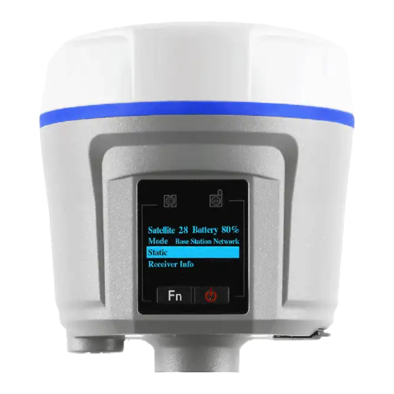
CHC I80 Maintenance Manual
Hide thumbs
Also See for I80:
- User manual (103 pages) ,
- Quick start manual (28 pages) ,
- Quick manual (10 pages)
Table of Contents
Advertisement
Advertisement
Table of Contents

Subscribe to Our Youtube Channel
Summary of Contents for CHC I80
- Page 1 Maintenance Manual...
-
Page 2: Table Of Contents
Contents 1:Power on/off problem........................- 2 - 1.1 When insert battery or use 12 V external power supply, the power LED is off....- 2 - 1.2:Auto power off problem:...................- 3 - 1.3:LED flash Error: ......................- 4 - 2:Communication Problem ......................- 4 - 2.1:BT/ Wi-Fi problem ......................- 4 - 2.2:Com port/USB port problem ..................- 5 - 2.3: Internal storage problem ....................- 6 -... -
Page 3: 1:Power On/Off Problem
Repair & Solution 1: Power on/off problem When insert battery or use 12 V external power supply, the power LED is off Detection Method&Solution: (1)Detect the input voltage of power supply. The external power supply should be more than 12 V, the battery should be 6.9V to 8.3V. If the detecting voltage is less than the minimum value, please replace the power supply or battery. -
Page 4: Auto Power Off Problem
: point out as picture 1.2:Auto power off problem: Fault description: When use the power supply, the receiver will auto power off. Detection Method&Solution: (1)Detect the serial FPC flexible PCB. Separate the receiver to check the band correctly install or not. If not, please re-install the FPC flexible PCB. -
Page 5: Led Flash Error
(2) Mainboard error caused lights abnormal when power on. If so, please replace the mainboard. (3) i80 flexible circuit board is not good and the LDE circuit does not make sense. If so, please replace the FPC flexible circuit board. -
Page 6: Com Port/Usb Port Problem
FB11 as picture attached : 2.2:Com port/USB port problem Fault description: The receiver cannot make the connection to the PC with the serial cable. Detection Method &Solution: (1)The serial cable has some problem. If so, please replace another serial cable to have a try. (2)Detect the serial FPC flexible circuit board. -
Page 7: Internal Storage Problem
The memory disk cannot be read when the receiver connected with the PC. Detection Method&Solution: (1)The USB data cable meets some problem and it also cannot connect with other i80. Please replace the USB data cable and have a try. (2) PFC flexible circuit board faults. - Page 8 If not, please replace the mainboard. ( FB13: The arrow point out the FB13 - 7 -...
-
Page 9: 3: Searching Satellites Problem
3: Searching satellites problem 3.1:Not searching satellites Fault description: After power on the receiver cannot search the satellites Detection Method&Solution: (1)GPS antenna damage, If yes please replace the antenna (2) Receiver OEM board problem, if the OEM board cannot reset normally, no output voltage, or OEM board register code lost, please reset the OEM board first and then check the OEM board output voltage, the normal OEM board output voltage is 3.3V,or Re-register the OEM board. -
Page 10: 4:Network Problem
4:Network problem The receiver cannot dial on, showing offline on the webpage, Network module continuously resetting. Detection Method&Solution: (1)Sim card error, if yes please replace a sim card (2)Sim Card slot problem, if yes please replace a sim card slot (3)GPRS module problem, please detect the voltage of the GPRS module, the normal output voltage is 4V, otherwise please replace the mainboard. -
Page 11: 5: Radio Problem
5: Radio problem 5.1: Cannot get the radio signal frequency setting not successful In rover radio mode, it cannot get the radio signal, Radio LED didn’t flash. Detection Method&Solution: (1) Wrong settings if yes check all the settings and set the right parameters (2) Radio module problem(please check the power supply voltage R17:3.3V/R15:4V/R16:5V/R18:9V)if the power voltage is not correct please replace the radio module... -
Page 12: 6:Shell Problem
The Radio signal not stable, Radio working distance short Detection Method &Solution: (1)Radio module broken if yes please replace the radio module (2)Rod antenna attenuation, if yes please replace the antenna. (3)Radio module connect cable problem, if yes please replace the mainboard 6:Shell problem: 6.1 Battery cover problem, Battery cover cannot shut, battery connector broken. -
Page 13: 7:Tilt Problem
7:Tilt problem 7.1 Cannot detect the tilt nodule cannot proceed the tilt alignment. Detection Method&Solution: (1) Tilt module broken, it cannot work, cannot alignment if yes please replace the mainboard. (2) Receiver register code overdue cause the tilt module not work if yes please re-register the receiver.


Need help?
Do you have a question about the I80 and is the answer not in the manual?
Questions and answers