
Related Manuals for Pilz PNOZ m EF Multi Link


Summary of Contents for Pilz PNOZ m EF Multi Link
- Page 1 PNOZ m EF Multi Link Configurable Control System PNOZmulti Operating Manual1003018EN03...
- Page 2 Preface This document is the original document. All rights to this documentation are reserved by Pilz GmbH & Co. KG. Copies may be made for internal purposes. Suggestions and comments for improving this documentation will be gratefully received. Pilz®, PIT®, PMI®, PNOZ®, Primo®, PSEN®, PSS®, PVIS®, SafetyBUS p®, SafetyEYE®, SafetyNET p®, the spirit of safety® are registered and protected trademarks of Pilz GmbH & Co. KG in some countries. SD means Secure Digital...
-
Page 3: Table Of Contents
Content Section 1 Introduction Validity of documentation Using the documentation Definition of symbols Section 2 Overview Scope of supply Unit features Front view Section 3 Safety Intended use System requirements Safety regulations 3.3.1 Use of qualified personnel 3.3.2 Warranty and liability 3.3.3 Disposal 3.3.4 For your safety Section 4 Function Description Integrated protection mechanisms Functions System reaction time Block diagram Section 5 Installation General installation guidelines Dimensions Connect the base unit and expansion modules Section 6 Commissioning Wiring Connection Download modified project to the PNOZmulti safety system Section 7 Operation Messages... -
Page 4: Operating Manual Pnoz M Ef Multi Link
Introduction Introduction Validity of documentation This documentation is valid for the product PNOZ m EF Multi Link. It is valid until new docu mentation is published. This operating manual explains the function and operation, describes the installation and provides guidelines on how to connect the product. Using the documentation This document is intended for instruction. Only install and commission the product if you have read and understood this document. The document should be retained for future ref erence. Definition of symbols Information that is particularly important is identified as follows: DANGER! This warning must be heeded! It warns of a hazardous situation that poses an immediate threat of serious injury and death and indicates preventive measures that can be taken. WARNING! This warning must be heeded! It warns of a hazardous situation that could lead to serious injury and death and indicates preventive measures that can be taken. CAUTION! This refers to a hazard that can lead to a less serious or minor injury plus material damage, and also provides information on preventive measures that can be taken. NOTICE This describes a situation in which the product or devices could be dam aged and also provides information on preventive measures that can be taken. It also highlights areas within the text that are of particular import ance. Operating Manual PNOZ m EF Multi Link 1003018EN03... - Page 5 Introduction INFORMATION This gives advice on applications and provides information on special fea tures. Operating Manual PNOZ m EF Multi Link 1003018EN03...
-
Page 6: Overview
Overview Overview Scope of supply Unit features Using the product PNOZ m EF Multi Link: Link module to safely connect two configurable control systems PNOZmulti 2. The product has the following features: Connection options: – Two base units PNOZmulti 2 Can be configured in the PNOZmulti Configurator Pointtopoint connection via 4core shielded and twistedpair cable 32 virtual inputs and 32 virtual outputs Status indicators Max. 4 PNOZ m EF Multi Link can be connected to the base unit LEDs for – Operating state – Error – Connection status Plugin connection terminals: either springloaded terminal or screw terminal available as an accessory (see order reference) Operating Manual PNOZ m EF Multi Link 1003018EN03... -
Page 7: Front View
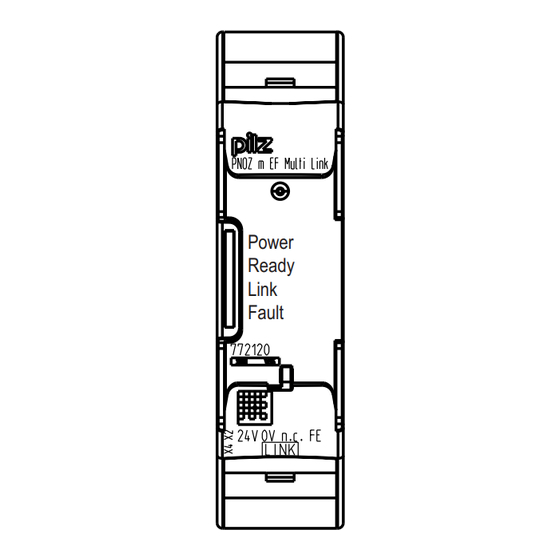
Overview Front view Power Ready Link Fault Legend: – 0 V, 24 V:Supply connections – FE: Functional earth Link: Connection LEDs: – Power – Ready – Link – Fault Operating Manual PNOZ m EF Multi Link 1003018EN03... -
Page 8: Safety
Safety Safety Intended use The expansion module is used for the pointtopoint connection of safe virtual inputs and outputs between two base units. The expansion module may only be connected to a base unit from the configurable control system PNOZmulti 2 (please refer to the document "PNOZmulti System Expansion" for de tails of the base units that can be connected). The configurable control system PNOZmulti is used for the safetyrelated interruption of safety circuits and is designed for use in: ESTOP equipment Safety circuits in accordance with VDE 0113 Part 1 and EN 602041 Intended use includes making the electrical installation EMCcompliant. The product is de signed for use in an industrial environment. It is not suitable for use in a domestic environ ment, as this can lead to interference. The following is deemed improper use in particular: Any component, technical or electrical modification to the product Use of the product outside the areas described in this manual Use of the product outside the technical details (see chapter entitled “Technical De tails”) System requirements Please refer to the "Product Modifications" document in the "Version overview" section for details of which versions of the base unit and PNOZmulti Configurator can be used for this product. Safety regulations 3.3.1 Use of qualified personnel The products may only be assembled, installed, programmed, commissioned, operated, maintained and decommissioned by competent persons. A competent person is someone who, because of their training, experience and current pro fessional activity, has the specialist knowledge required to test, assess and operate the work equipment, devices, systems, plant and machinery in accordance with the general standards and guidelines for safety technology. It is the company’s responsibility only to employ personnel who: Are familiar with the basic regulations concerning health and safety / accident preven tion Have read and understood the information provided in this description under "Safety" And have a good knowledge of the generic and specialist standards applicable to the specific application. Operating Manual PNOZ m EF Multi Link 1003018EN03... -
Page 9: Warranty And Liability
Safety 3.3.2 Warranty and liability All claims to warranty and liability will be rendered invalid if The product was used contrary to the purpose for which it is intended Damage can be attributed to not having followed the guidelines in the manual Operating personnel are not suitably qualified Any type of modification has been made (e.g. exchanging components on the PCB boards, soldering work etc.). 3.3.3 Disposal In safetyrelated applications, please comply with the mission time t in the safetyre lated characteristic data. When decommissioning, please comply with local regulations regarding the disposal of electronic devices (e.g. Electrical and Electronic Equipment Act). 3.3.4 For your safety The unit meets all necessary conditions for safe operation. However, you should always en sure that the following safety requirements are met: This operating manual only describes the basic functions of the unit. Information on the advanced functions can be found in the online help for the PNOZmulti Configurator and in the PNOZmulti technical catalogue. Only use these functions after you have read and understood the documentation. All necessary documentation can be found on the PNOZmulti Configurator CD. Do not open the housing or make any unauthorised modifications. Please make sure you shut down the supply voltage when performing maintenance work (e.g. exchanging contactors). Operating Manual PNOZ m EF Multi Link 1003018EN03... -
Page 10: Function Description
Function Description Function Description Integrated protection mechanisms The relay conforms to the following safety criteria: The circuit is redundant with builtin selfmonitoring. The safety function remains effective in the case of a component failure. Functions The link module PNOZ m EF Multi Link is used to safely transfer the input information from 32 virtual inputs and 32 virtual outputs between two PNOZmulti systems. One link module is assigned to each base unit. Data is exchanged cyclically. The function of the inputs and outputs on the control system depends on the safety circuit created using the PNOZmulti Configurator. A chip card is used to download the safety cir cuit to the base unit. The base unit has 2 microcontrollers that monitor each other. They evaluate the input circuits on the base unit and expansion modules and switch the outputs on the base unit and expansion modules accordingly. The LEDs on the base unit and expansion modules indicate the status of the configurable control system PNOZmulti. The online help on the PNOZmulti Configurator contains descriptions of the operating modes and all the functions of the control system, plus connection examples. Data exchange: Data is exchanged cyclically. After the end of a PNOZmulti cycle, each base unit sends its output data to its link mod ule. This output data is immediately sent to the link module on the other base unit. At the same time, the base unit reads the input data from the link module. Connection of multiple base units: Any number of base units can be connected via link modules. Two link modules are re quired for a connection between two base units. However, only a maximum of 4 link mod ules may be connected to any one base unit. Virtual inputs and outputs: Inputs and outputs for both PNOZmulti systems are assigned in the PNOZmulti Configur ator. Inputs and outputs with the same number are assigned to each other, e.g. output o5 on one PNOZmulti system to input i5 on the other PNOZmulti system. Operating Manual PNOZ m EF Multi Link 1003018EN03... -
Page 11: System Reaction Time
Function Description Base unit 2 Base unit 1 Virtual inputs Virtual outputs Virtual outputs Virtual inputs System reaction time Calculation of the maximum reaction time between an input switching off and a linked out put in the system switching off is described in the document "System Expansion". Block diagram 24V 0V n.c.FE CA- CB+ CB- CGround Power Operating Manual PNOZ m EF Multi Link 1003018EN03... -
Page 12: Installation
Installation Installation General installation guidelines The unit should be installed in a control cabinet with a protection type of at least IP54. Fit the safety system to a horizontal mounting rail. The venting slots must face upwards and downwards. Other mounting positions could destroy the safety system. Use the locking slide on the rear of the unit to attach it to a mounting rail. In environments exposed to heavy vibration, the unit should be secured using a fixing element (e.g. retaining bracket or end angle). Open the locking slide before lifting the unit from the mounting rail. To comply with EMC requirements, the mounting rail must have a low impedance con nection to the control cabinet housing. The ambient temperature of the PNOZmulti units in the control cabinet must not exceed the figure stated in the technical details, otherwise air conditioning will be required. CAUTION! Damage due to electrostatic discharge! Electrostatic discharge can damage components. Ensure against discharge before touching the product, e.g. by touching an earthed, conductive sur face or by wearing an earthed armband. Dimensions 22,5 (0.88") Operating Manual PNOZ m EF Multi Link 1003018EN03... -
Page 13: Connect The Base Unit And Expansion Modules
Installation Connect the base unit and expansion modules Connect the base unit and the expansion module as described in the operating instructions for the base units. Connect the black/yellow terminator to the expansion module. Install the expansion module in the position in which it is configured in the PNOZmulti Configurator. Operating Manual PNOZ m EF Multi Link 1003018EN03... -
Page 14: Commissioning
Commissioning Commissioning Wiring The wiring is defined in the circuit diagram of the PNOZmulti Configurator. Note: Information given in the "Technical details" must be followed. The power supply must meet the regulations for extra low voltages with protective sep aration. 2 connection terminals are available for each of the supply connections 24 V and 0 V. This means that the supply voltage can be looped through several connections. The current at each terminal may not exceed 3 A. The max. cable length between two link modules on a connection with one link module – PNOZ ml1p <V2.0: 100 m – PNOZ ml1p from V2.0, PNOZ mml1p, PNOZ m EF Multi Link: 1000 m Connect the inputs and outputs from two link modules with 4core shielded cable. The cables must be twisted in pairs (see "Preparing for operation"). Note the crossover cabling, e.g. CA+ with CB+. The cables must be classified into a minimum of Category 5 in accordance with ISO/ IEC 11801. CAUTION! Only connect and disconnect the expansion module when the supply voltage is switched off. Connection RJ45 socket 8pin Layout CA n.c. n.c. CB n.c. n.c. Shield CGround Operating Manual PNOZ m EF Multi Link 1003018EN03... -
Page 15: Download Modified Project To The Pnozmulti Safety System
Commissioning Supply voltage n.c. Connecting 2 base units PNOZmulti 2 via PNOZ m EF Multi Link PNOZ m EF Multi Link PNOZ m EF Multi Link Connection cable configuration when using: 2 plugin connectors "SafetyNET p Connector RJ45" 1 connection cable "SafetyNET p Cable" (available as accessory, see order reference) SafetyNET p Connector RJ45 SafetyNET p Connector RJ45 yellow orange yellow blue white blue white orange PIN 6 PIN 1 PIN 2... -
Page 16: Operation
Operation Operation When the supply voltage is switched on, the PNOZmulti safety system copies the configur ation from the chip card. The LEDs "POWER","DIAG", "FAULT", "IFAULT" and "OFAULT" light up on the base unit. The PNOZmulti safety system is ready for operation when the "POWER" and "RUN" LEDs on the base unit and the "READY" LED on the PNOZ m EF Multi Link are lit continuously. Messages Legend: LED on LED flashes LED off LED status Meaning Power No supply voltage Gree Supply voltage is present Ready Gree The unit is ready for operation The unit is not ready for operation Fault External fault Internal fault No fault Link Yel Connection available to another link module No connection available to another link module Operating Manual PNOZ m EF Multi Link 1003018EN03... -
Page 17: Fault Detection
Operation Fault detection Each base unit contains information about its own link module (in order, defective, no supply voltage) the status of the connection (yes, no) the operating status of the connected base unit (RUN, STOP) When the connection is interrupted, the base units switch the virtual inputs to zero. The base units remains in a RUN condition. Defective link module: The corresponding base unit switches to a STOP condition. The virtual outputs on the link module are set to zero. The connected base unit remains in a RUN condition. Operating Manual PNOZ m EF Multi Link 1003018EN03... -
Page 18: Technical Details
Technical details Technical details General Approvals BG, CCC, CE, GOST, TÜV, cULus Listed Application range Failsafe Electrical data Supply voltage Module supply Voltage 24 V Kind Voltage tolerance 15 %/+20 % Output of external power supply (DC) 5,0 W Potential isolation Supply voltage Supply to the system internal Via base unit Voltage 3,3 V Kind Status indicator Fieldbus interface Galvanic isolation Times Max. data transmission time 5 ms Environmental data Ambient temperature In accordance with the standard EN 60068214 Temperature range 0 60 °C Storage temperature In accordance with the standard EN 6006821/2 Temperature range 25 70 °C Climatic suitability... - Page 19 Technical details Environmental data Airgap creepage In accordance with the standard EN 611312 Overvoltage category Pollution degree Rated insulation voltage 30 V Protection type In accordance with the standard EN 60529 Mounting area (e.g. control cabinet) IP54 Housing IP20 Terminals IP20 Potential isolation Potential isolation between Module and supply voltage Type of potential isolation Protective separation Rated surge voltage 2500 V Potential isolation between Module and system voltage Type of potential isolation Protective separation Rated surge voltage 2500 V Mechanical data Mounting position Horizontal on top hat rail DIN rail Top hat rail 35 x 7,5 EN 50022 Recess width 27 mm Material Bottom Front Conductor cross section with screw terminals...
-
Page 20: Safety Characteristic Data
Technical details Where standards are undated, the 201301 latest editions shall apply. Safety characteristic data Operating EN ISO EN ISO EN 62061 EN 62061 IEC 61511 IEC 61511 EN ISO mode 138491: 138491: 138491: SIL CL [1/h] 2008 2008 2008 Category [year] – PL e Cat. 4 SIL CL 3 8,82E09 SIL 3 3,86E05 All the units used within a safety function must be considered when calculating the safety characteristic data. INFORMATION A safety function's SIL/PL values are not identical to the SIL/PL values of the units that are used and may be different. We recommend that you use the PAScal software tool to calculate the safety function's SIL/PL values. Operating Manual PNOZ m EF Multi Link 1003018EN03... -
Page 21: Order Reference
Order reference Order reference Module Product type Features Order no. PNOZ m EF Multi Link Expansion module 772 120 Accessories Connection terminals Product type Features Order no. Spring terminals PNOZ Springloaded terminals, 1 pieces 783 538 mmc2p, mml1p 1 pc. Spring terminals PNOZ Springloaded terminals, 10 pieces 783 539 mmc2p,mml1p 10 pcs Screw terminals PNOZ Screw terminals, 1 piece 793 538 mmc2p, mml1p 1 pc. Screw terminals PNOZ Screw terminals, 10 piece 793 539 mmc2p,mml1p 10 pcs. Terminator, jumper Product type Features Order no. PNOZ mm0.xp connector Jumper yellow/black to connect the modules, 1 piece 779 260 left Cable Product type Features Order no. - Page 22 Front cover Support Technical support is available from Pilz round the clock. Americas Australia Scandinavia Brazil +61 3 95446300 +45 74436332 +55 11 97569-2804 Spain Canada Europe +34 938497433 Switzerland +1 888-315-PILZ (315-7459) Austria +43 1 7986263-0 +41 62 88979-30 Mexico...
Need help?
Do you have a question about the PNOZ m EF Multi Link and is the answer not in the manual?
Questions and answers