
Related Manuals for Pilz PNOZ m EF 4DI4DOR


Summary of Contents for Pilz PNOZ m EF 4DI4DOR
- Page 1 PNOZ m EF 4DI4DOR Configurable, safe small controllers PNOZmulti 2 Operating Manual-1002702-EN-08...
- Page 2 Preface This document is the original document. All rights to this documentation are reserved by Pilz GmbH & Co. KG. Copies may be made for the user's internal purposes. Suggestions and comments for improving this documenta- tion will be gratefully received.
-
Page 3: Table Of Contents
Technical details ........................Safety characteristic data ......................Classification according to ZVEI, CB24I ................... Supplementary data ......................Service life graph for the relay contacts..................Permitted ambient temperature Tamb dependent on the total current Isum ......Operating Manual PNOZ m EF 4DI4DOR 1002702-EN-08... - Page 4 Contents Order reference ........................10.1 Product ............................. 10.2 Accessories ..........................Operating Manual PNOZ m EF 4DI4DOR 1002702-EN-08...
-
Page 5: Introduction
Introduction Introduction Validity of documentation This documentation is valid for the product PNOZ m EF 4DI4DOR. It is valid until new doc- umentation is published. This operating manual explains the function and operation, describes the installation and provides guidelines on how to connect the product. - Page 6 Introduction INFORMATION This gives advice on applications and provides information on special fea- tures. Operating Manual PNOZ m EF 4DI4DOR 1002702-EN-08...
-
Page 7: Overview
Expansion module PNOZ m EF 4DI4DOR Jumper Unit features Application of the product PNOZ m EF 4DI4DOR: Expansion module for connection to a base unit from the PNOZmulti 2 system. The product has the following features: Can be configured in the PNOZmulti Configurator... -
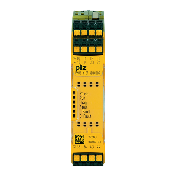
Page 8: Front View
Overview Front view Legend: Inputs I0 – I3 Outputs O0 – O3 LEDs: – POWER – Run – Diag – Fault – I Fault – O Fault Operating Manual PNOZ m EF 4DI4DOR 1002702-EN-08... -
Page 9: Safety
Example: Protected inside space or control cabinet with protection type IP54 and corres- ponding air conditioning. The module PNOZ m EF 4DI4DOR can be used in furnaces in accordance with EN 298. If the module's relay outputs shut down the entire fuel supply and the furnace is used in con- tinuous operation, appropriate external measures must be used to establish diversity of the shutdown elements (requirement of EN 50156-1). -
Page 10: Safety Regulations
(e.g. Electrical and Electronic Equipment Act). 3.3.5 For your safety The unit meets all the necessary conditions for safe operation. However, you should always ensure that the following safety requirements are met: Operating Manual PNOZ m EF 4DI4DOR | 10 1002702-EN-08... - Page 11 Do not open the housing or make any unauthorised modifications. Please make sure you shut down the supply voltage when performing maintenance work (e.g. exchanging contactors). Operating Manual PNOZ m EF 4DI4DOR | 11 1002702-EN-08...
-
Page 12: Function Description
Calculation of the maximum reaction time between an input switching off and a linked out- put in the system switching off is described in the document "PNOZmulti System Expan- sion". Block diagram Module Supply Data (FS) Operating Manual PNOZ m EF 4DI4DOR | 12 1002702-EN-08... -
Page 13: Installation
Electrostatic discharge can damage components. Ensure against discharge before touching the product, e.g. by touching an earthed, conductive sur- face or by wearing an earthed armband. Dimensions in mm 22,5 (0.88") Operating Manual PNOZ m EF 4DI4DOR | 13 1002702-EN-08... -
Page 14: Connecting The Base Unit And Expansion Modules
Please refer to the document "PNOZmulti System Expansion" for details of the number of modules that can be connected to the base unit and the module types. Operating Manual PNOZ m EF 4DI4DOR | 14 1002702-EN-08... -
Page 15: Commissioning
Sufficient fuse protection must be provided on all output contacts with capacitive and in- ductive loads. Connection Input circuit Single-channel Dual-channel Example: E-Stop without detection of shorts across contacts Example: E-Stop with detection of shorts across contacts Operating Manual PNOZ m EF 4DI4DOR | 15 1002702-EN-08... -
Page 16: Download Modified Project To The Pnozmulti System
Proceed as described in the operating manual for the base unit. NOTICE For the commissioning and after every user program change, you must check whether the safety devices are functioning correctly. Operating Manual PNOZ m EF 4DI4DOR | 16 1002702-EN-08... -
Page 17: Operation
No supply voltage Expansion module PNOZ m EF 4DI4DOR running without er- ror. Expansion module PNOZ m EF 4DI4DOR is in a STOP condi- tion. Internal error on the expansion module PNOZ m EF 4DI4DOR or on the overall system. Expansion module is in a safe condition. -
Page 18: Function Test Of The Relay Outputs
Start the device again or open the safety contacts (switch off output), so that the internal diagnostics can check the correct opening of the safety contacts for SIL CL 3/PL e at least 1x per month for SIL CL 2/PL d at least 1x per year Operating Manual PNOZ m EF 4DI4DOR | 18 1002702-EN-08... -
Page 19: Technical Details
10 mA Max. current Max. power 1500 VA DC1 at 24 V Min. current 10 mA Max. current Max. power 144 W Utilisation category In accordance with the standard EN 60947-5-1 Operating Manual PNOZ m EF 4DI4DOR | 19 1002702-EN-08... - Page 20 EN 60068-2-30, EN 60068-2-78 Condensation during operation Not permitted Max. operating height above sea level 2000 m EN 61131-2 Vibration In accordance with the standard EN 60068-2-6 Frequency 5 - 150 Hz Acceleration Operating Manual PNOZ m EF 4DI4DOR | 20 1002702-EN-08...
- Page 21 Conductor cross section with spring-loaded terminals: Flexible with/without crimp connector 0,2 - 2,5 mm², 24 - 12 AWG Spring-loaded terminals: Terminal points per connec- tion Stripping length with spring-loaded terminals 9 mm Operating Manual PNOZ m EF 4DI4DOR | 21 1002702-EN-08...
-
Page 22: Safety Characteristic Data
A safety function's SIL/PL values are not identical to the SIL/PL values of the units that are used and may be different. We recommend that you use the PAScal software tool to calculate the safety function's SIL/PL values. Operating Manual PNOZ m EF 4DI4DOR | 22 1002702-EN-08... -
Page 23: Classification According To Zvei, Cb24I
Input Interfaces Drain Interface Module Class Source Interface Sensor Class C2, C3 Drain parameters Test pulse duration, safety outputs 500 µs Min. input resistance 5,6 kOhm Max. capacitive load 126 nF Operating Manual PNOZ m EF 4DI4DOR | 23 1002702-EN-08... -
Page 24: Supplementary Data
The service life graphs indicate the number of cycles from which failures due to wear must be expected. The wear is mainly caused by the electrical load; the mechanical load is negli- gible. Switching current (A) Fig.: Service life graphs at 24 VDC and 230 VAC Operating Manual PNOZ m EF 4DI4DOR | 24 1002702-EN-08... - Page 25 With capacitive loads, any power surges that occur must be noted. With DC contact- ors, use flywheel diodes for spark suppression. We recommend you use semiconductor outputs to switch 24 VDC loads. Operating Manual PNOZ m EF 4DI4DOR | 25 1002702-EN-08...
-
Page 26: Permitted Ambient Temperature Tamb Dependent On The Total Current Isum
Max. permitted total current of relay outputs at an ambient temperature of < 45 °C: 24 A Max. permitted total current of relay outputs at an ambient temperature of = 60 °C: 20 A Operating Manual PNOZ m EF 4DI4DOR | 26... - Page 27 751 004 Set screw terminals 1 set of screw terminals 750 004 Terminator, jumper Product type Features Order no. PNOZ mm0.xp connector Jumper yellow/black to connect the modules, 10 pieces 779 260 left Operating Manual PNOZ m EF 4DI4DOR | 27 1002702-EN-08...
- Page 28 We are represented internationally. Please refer to our homepage www.pilz.com for further details or contact our headquarters. Headquarters: Pilz GmbH & Co. KG, Felix-Wankel-Straße 2, 73760 Ostfildern, Germany Telephone: +49 711 3409-0, Telefax: +49 711 3409-133, E-Mail: info@pilz.com, Internet: www.pilz.com...
Need help?
Do you have a question about the PNOZ m EF 4DI4DOR and is the answer not in the manual?
Questions and answers