Table of Contents
Advertisement
Advertisement
Table of Contents

Related Manuals for Pilz PRBT 6


Summary of Contents for Pilz PRBT 6
- Page 1 Service Robotics Modules Robotics System Description-1004870-EN-05...
- Page 2 Preface This document is the original document. All rights to this documentation are reserved by Pilz GmbH & Co. KG. Copies may be made for the user's internal purposes. Suggestions and comments for improving this documenta- tion will be gratefully received.
-
Page 3: Table Of Contents
Retaining the documentation ....................Definition of symbols......................... Overview ..........................Overview of industrial robots with service robotics modules from Pilz ........Overview of robot arm from Pilz ....................Overview of teach pendant from Pilz ..................Overview of robot control module from Pilz ................ - Page 4 Positions and orientation of the coordinate systems on the robot arm ........Tool centre point (TCP) ......................Building an industrial robot with service robotics modules from Pilz ........Planning the position for the brake test ..................Planning an external emergency stop device ................
- Page 5 Contents Diagnostics and troubleshooting ..................Technical details ........................12.1 Safety characteristic data ......................Order reference ........................13.1 Product ............................. 13.2 Accessories ..........................Appendix ..........................14.1 Hash value for integrity check of a download ................14.1.1 Calculate hash value with the command line tool "Certutil" ............
-
Page 6: Introduction
This operating manual contains information about the intended use of the service robotics modules from Pilz. Using the robot arm PRBT 6 together with the robot control module PRCM1 (control cab- inet) and the teach pendant PRTM1, an industrial robot can be built that corresponds to the harmonised standard EN ISO 10218-1. -
Page 7: Definition Of Symbols
Introduction Definition of symbols Information that is particularly important is identified as follows: DANGER! This warning must be heeded! It warns of a hazardous situation that poses an immediate threat of serious injury and death and indicates preventive measures that can be taken. WARNING! This warning must be heeded! It warns of a hazardous situation that could lead to serious injury and death and indicates preventive measures that can... -
Page 8: Overview
Overview of industrial robots with service robotics modules from Pilz Using the robot arm PRBT 6 together with the robot control module PRCM1 (control cab- inet) and the teach pendant PRTM1, an industrial robot can be built that corresponds to the harmonised standard EN ISO 10218-1. - Page 9 Communication interface (Ethernet) for transmitting the robot program from the teach pendant to the motion controller Robot control module PRCM1 Control cabinet with Safety control system from Pilz including – Pre-installed PSS 4000 user program – Digital FS and ST inputs – Digital FS outputs Motion controller from Pilz including –...
-
Page 10: Overview Of Robot Arm From Pilz
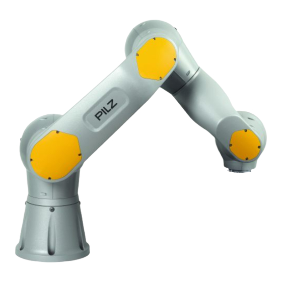
Overview Overview of robot arm from Pilz The robot arm PRBT 6 is a multi-purpose manipulator with 6 axes. This type of manipulator is also called an articulated robot. The robot arm may be classified as a light-weight robot arm. -
Page 11: Overview Of Teach Pendant From Pilz
Overview of teach pendant from Pilz The teach pendant PRTM1 is a mobile control unit that is used by programmers for the pro- gramming, commissioning and diagnostics of industrial robots from Pilz. The teach pendant is equipped with Software for programming, commissioning and diagnostics of the Pilz industrial robot E-STOP pushbutton for triggering the robot’s emergency stop function... - Page 12 Overview Fig.: Front view of the teach pendant Legend Power button Status LEDs: When the supply voltage is applied, the LED will light up green The LED will light up green when the motion enable for the drives is present Fault diagnostics The LED will light up red when diagnostic messages from the safety control system and/or the motion controller are present.
- Page 13 Overview [3a] [3b] Fig.: Rear view of the teach pendant Legend Control buttons for moving the axes of the robot arm (only for manual operating modes) Handle and device bracket [3a] Enabling switch [3b] Enabling switch System Description Service Robotics Modules | 13 1004870-EN-05...
-
Page 14: Overview Of Robot Control Module From Pilz
Overview Overview of robot control module from Pilz The robot control module PRCM1 (control cabinet) contains all the components needed to control the robot arm and any additional equipment depending on the application (e.g. end- effectors, indicator lights) and to evaluate the signals from any additional equipment de- pendent on the application (e.g. - Page 15 Overview The robot control module PRCM1 (control cabinet) is used as a component to operate the industrial robot in compliance with the standards in accordance with EN ISO 10218-1. The robot control module PRCM1 (control cabinet) is constructed in accordance with IEC 60204-1.
-
Page 16: Safety
Refer to the safety guidelines in the operating manuals for the relevant products. Please also read the information in the Operating manual for the robot arm PRBT 6 Operating manual and online help for the teach pendant PRTM1 Assembly instructions and operating manual for the relevant end-effector... -
Page 17: Intended Use
Safety Intended use The industrial robot is classed as partly completed machinery in the context of the EC Ma- chinery Directive. The industrial robot is intended for use within an industrial robot system. Commissioning and operation are only permitted under the following conditions: The system/plant integrator has integrated the industrial robot in such a way that it consti- tutes a standard-compliant industrial robot system when combined with other compon- ents... -
Page 18: Foreseeable Misuse And Abuse
Safety Foreseeable misuse and abuse The robot arm is not suitable for use in areas with increased environmental requirements (e.g. potentially explosive areas). The following is an example of misuse or abuse and is not permitted: – Use for the transport of people or animals –... -
Page 19: Safety Guidelines
Safety Safety guidelines 3.4.1 Use of qualified personnel The products may only be assembled, installed, programmed, commissioned, operated, maintained and decommissioned by competent persons. A competent person is a qualified and knowledgeable person who, because of their train- ing, experience and current professional activity, has the specialist knowledge required. To be able to inspect, assess and operate devices, systems and machines, the person has to be informed of the state of the art and the applicable national, European and international laws, directives and standards. - Page 20 Safety The system or plant integrator is obligated to: Perform a risk assessment Implement the safety functions and protective devices resulting from the risk assessment. Assemble the robot arm Connect the robot arm Create the operating manual for the complete plant/machine Issue the declaration of conformity Affix the CE mark Robot operator...
-
Page 21: Emcd
Safety EMCD The product is designed for use in an industrial environment. Warranty and liability All claims to warranty and liability will be rendered invalid if The product was used contrary to the purpose for which it is intended, Damage can be attributed to not having followed the guidelines in the manual, Operating personnel are not suitably qualified, Any type of modification has been made (e.g. -
Page 22: Function Description
Function description Function description Triggering of safety-related functions An industrial robot that is constructed using service robotics modules from Pilz has the fol- lowing devices to trigger safety-related functions: Emergency stop device (teach pendant PRTM1) Enabling device to allow the robot to move in manual operating modes (teach pendant... -
Page 23: Overview Of Stop Reactions
Function description Overview of stop reactions The table below shows the triggers for stop reactions, depending on the selected operating mode. The stop categories conform to the definition in EN 60204. Trigger Manual operating modes Automatic mode Emergency stop due to Controlled stop (stop cat- Controlled stop (stop cat- egory 1) - Page 24 Function description Trigger Manual operating modes Automatic mode Brake test faulty or brake test Controlled stop (stop cat- Controlled stop (stop cat- not conducted egory 1) egory 1) See section Brake test function [ Power failure Controlled stop Controlled stop (stop category 0) (stop category 0) Possible to restart once supply voltage is switched on...
-
Page 25: Emergency Stop Function
Function description Emergency stop function The emergency stop function can be triggered by The emergency stop pushbutton on the teach pendant An external emergency stop pushbutton The system or plant integrator is obligated to take the situations for emergency stop into ac- count in his risk analysis. - Page 26 Function description Reset after an emergency stop Once the emergency stop function has been triggered, the state that triggered it must be rectified before the emergency stop can be reset manually. The system or plant integrator is tasked with determining how the reset should occur. NOTICE Reset via the teach pendant or via an external reset device The reset must occur either via the teach pendant or via an external reset...
-
Page 27: Protective Stop Function For Protective Stop External
Function description Protective stop function for protective stop external The protective stop function can be triggered by various external safety devices. The system or plant integrator is obligated to take the situations for protective stop into ac- count in his risk analysis. The risk analysis must indicate the external safety devices that are required. - Page 28 Function description Reset after a protective stop Once the protective stop function has been triggered, the state that triggered it must be rec- tified before the protective stop can be reset automatically or manually. The system or plant integrator is tasked with determining whether the reset should occur automatically or manu- ally.
-
Page 29: Protective Stop Function For Psenmlock (Safety Gate Function)
Protective stop function for PSENmlock (safety gate function) The safety gate function can be requested by a PSENmlock from Pilz. The PSENmlock is a safety gate system for safe interlocking and safe guard locking. The system or plant integrator is obligated to take the situations in which a safety gate func- tion is requested into account in his risk analysis. - Page 30 Function description Reset after a protective stop Once the protective stop function has been triggered, the state that triggered it must be rec- tified before the protective stop can be reset automatically or manually. The system or plant integrator is tasked with determining whether the reset should occur automatically or manu- ally.
-
Page 31: Safe Retention With Holding Brakes
Function description Safe retention with holding brakes The robot arm is a vertical axis, or more specifically a gravity-loaded axis. Generally, ver- tical axes are held at standstill solely by the holding brake built into the drive motor. Mech- anical wear on the brake, for example, can cause the axis to drop or fall unintentionally due to gravity. -
Page 32: Enabling Function
Function description Enabling function The enabling device is used in the modes "Manual reduced speed" and "Manual high- speed", to enable the axes of the robot arm to be moved manually. The teach pendant has two enabling switches to control the enable. Both switches are con- nected in parallel, so both right and left-handed operation is possible. - Page 33 Function description – If both enabling switches are in the centre position and one of the enabling switches is fully depressed (change to panic position), then the robot movement will come to a controlled stop (SS1). NOTICE In one of the manual operating modes, if the enable has been continuously present (enabling device in centre position) for longer than 15 minutes, then the motion enable is automatically reset.
- Page 34 Function description Procedure for enable Triggering the enabling function initiates the following procedure: Operate enabling switch (centre position) Evaluation of switch position Centre position is detected Fig.: Evaluation of the enabling device when enabling switch is in the centre position Further information is available under Operating mode "Manual reduced speed"...
- Page 35 Function description Procedure for cancelling enable The enable is cancelled when there is a change from the centre position to the zero posi- tion or panic position. Cancelling the enable initiates the following procedure: Release or fully depress enabling switch Evaluation of signal Zero position or...
-
Page 36: Brake Test Function
Function description Brake test function The aim of the brake test is to check the effectiveness of the holding brakes on the robot arm. The safety function "Safe retention with holding brakes" is guaranteed while the brake test delivers a positive result; i.e. following the controlled stop of the robot arm drives (SS1), no hazard can arise due to suspended loads sagging. - Page 37 Function description CAUTION! Possible loss of the safety function "Safe retention with holding brakes" Loss of the safety function may lead to injury and/or material damage, de- pending on the application. If the monitoring time is exceeded or there was a failed brake test, the robot arm may no longer be operated in productive mode.
-
Page 38: Brake Test Function After A Cold Start
Function description 4.8.1 Brake test function after a cold start When the industrial robot is cold started (switch on supply voltage), the state of the holding brakes is unknown. For this reason, an immediate brake test is absolutely essential. After a cold start, the safety control system starts a timer and for this period of time issues a temporary motion enable for the robot arm (see Robot movement with time-limited motion enable [... - Page 39 Function description Exceeding the time for the temporary motion enable initiates the following procedure: The time for the temporary motion enable has been exceeded Display on teach pendant: "SS1 was triggered because the brake test was not performed" Fig.: SS1 due to the brake test not being performed In order to approach the brake test position after an SS1, a time-limited motion enable must be requested.
-
Page 40: Brake Test Function With Cyclical Brake Test
Function description 4.8.2 Brake test function with cyclical brake test As a cyclical brake test is always prescribed for the robot arm, monitoring of the cyclical brake test is always active. With a cyclical brake test, the safety control system is tasked with prompting the motion controller to perform a brake test as part of each cycle. - Page 41 Function description Exceeding the monitoring time initiates the following procedure: The monitoring time for the cyclical brake test has expired Display on teach pendant: "SS1 was triggered because the brake test was not performed" Fig.: SS1 due to the brake test not being performed In order to approach the brake test position after an SS1, a time-limited motion enable must be requested.
-
Page 42: Brake Test Function When Prompted Via The Teach Pendant
Function description 4.8.3 Brake test function when prompted via the teach pendant It is possible to be prompted about a brake test manually via the teach pendant. For this purpose the teach pendant contains a service program as the default robot program (see Default robot program for brake test [ 46]). -
Page 43: Brake Test Function With An External Prompt
Function description 4.8.4 Brake test function with an external prompt The safety control system may be provoked externally into sending a prompt to the motion controller regarding the brake test. This external prompt to perform the brake test may be necessary if the industrial robot is part of a production line, for example. -
Page 44: Evaluation Of Brake Test
Function description 4.8.5 Evaluation of brake test After a brake test has been performed in the robot arm, the robot arm reports the test res- ults for each axis to the motion controller. The test results are compiled in the motion con- troller and the result is downloaded to the safety control system for safe evaluation. - Page 45 Function description Evaluating the result of the brake test initiates the following procedure: Evaluate the result of the brake test Brakes OK? Update the monitoring status of the brake test Display on teach pendant: "Brake test was performed but failed" Fig.: Evaluate the result of the brake test In order to approach the repair or transport position after an SS1, a time-limited motion en- able must be requested.
-
Page 46: Default Robot Program For Brake Test
Function description 4.8.6 Default robot program for brake test Before a brake test can be performed, the robot arm must first be moved to an appropriate brake test position. The teach pendant contains a service program as the default robot pro- gram for this purpose. -
Page 47: Robot Movement With Time-Limited Motion Enable
Evaluation of brake test [ 44]). The brakes must be repaired by Pilz GmbH & Co. KG. Requesting a time-limited motion enable via the teach pendant If the operating mode "Automatic" with teach pendant is activated, in one of the above cases the robot operator can request a time-limited motion enable via the reset button on the teach pendant ("2nd"... -
Page 48: Operating Modes
Function description 4.10 Operating modes A distinction is made between automatic and manual operating modes. Automatic operating mode is the intended production mode of the plant or machine. The safeguards (e.g. closed safety gate) are activated in automatic mode. Operation in auto- matic operating mode is also called normal mode or productive mode. -
Page 49: Automatic" Operating Mode
Function description 4.10.1 "Automatic" operating mode After a cold start (switch on supply voltage) the industrial robot is always started in auto- matic operating mode. The start conditions in "Automatic" operating mode must be configured in advance via the teach pendant. The following options are available to select: (Cold) start in the operating mode "Automatic"... - Page 50 Function description If you switch from "Automatic" operating mode into one of the manual operating modes, the robot movement will come to a controlled stop (SS1). The controlled stop will occur ir- respective of whether automatic mode was started externally or via the teach pendant. Further information is available at Changing the operating mode and motion enable [...
-
Page 51: Operating Mode "Manual Reduced Speed
Function description 4.10.2 Operating mode "Manual reduced speed" This operating mode can only be triggered via the teach pendant (see Changing the operat- ing mode and motion enable [ 57]). It enables someone to move the axes of the robot arm manually. - Page 52 Function description NOTICE The system or plant integrator is obligated to pay particular attention in their risk analysis to the situations in which people have access to the danger zone and in which it is possible to stand below the axes. NOTICE The system or plant integrator is responsible for taking into account the re- quirements from the respective current standard EN ISO 10218-2 or taking...
- Page 53 Function description Please note: If no control button is operated, the robot movement will stop. This stop corresponds to a controlled stop of the robot movement; i.e. this stop does not trigger the stop function SS1. However, if the enabling device on the teach pendant is not operated, the stop function SS1 is triggered.
-
Page 54: Operating Mode "Manual High-Speed
Function description 4.10.3 Operating mode "Manual high-speed" This operating mode can only be triggered via the teach pendant (see Changing the operat- ing mode and motion enable [ 57]). It enables someone to move the axes of the robot arm manually. This operating mode may only be used to verify the robot program. - Page 55 Function description NOTICE The system or plant integrator is responsible for taking into account the re- quirements from the respective current standard EN ISO 10218-1 or taking equivalent measures. Procedure Waiting for enable Stop function SS1 was triggered (safety control system) Safety control system: Enable for operating mode "Manual high-speed"...
- Page 56 Function description Please note: If the "Play" button is not operated or the end of the program is reached, the robot move- ment will stop. This stop corresponds to a controlled stop of the robot movement; i.e. this stop does not trigger the stop function SS1. However, if the enabling device on the teach pendant is not operated, the stop function SS1 is triggered.
-
Page 57: Changing The Operating Mode And Motion Enable
Function description 4.10.4 Changing the operating mode and motion enable The teach pendant is required in order to change the operating mode. Procedure Operate key switch: Lock -> Unlock Change operating mode Operate key switch: Unlock -> Lock Has a different operating mode been selected? Robot movement stopped... - Page 58 Function description NOTICE If the operating mode "Manual high-speed" is active and there is no enable from the enabling device for more than 5 minutes, the operating mode "Manual high-speed" is automatically deactivated and switches simultan- eously to "Manual reduced speed". NOTICE In one of the manual operating modes, if the enable has been continuously present (enabling device in centre position) for longer than 15 minutes, then...
-
Page 59: Stopping Time And Stopping Distance In The Event Of Stop 1
Function description 4.11 Stopping time and stopping distance in the event of STOP 1 Stopping time at maximum speed = 90°/s Axis = 235.02 ms stopping_STOP1_100 Stopping time at 66% of maximum speed = 60°/s Axis = 168.35 ms stopping_STOP1_66 Stopping time at 33% of maximum speed = 30°/s Axis = 101.69 ms... -
Page 60: Stopping Time In The Event Of A Complete Stop
Function description 4.12 Stopping time in the event of a complete stop A complete stop includes the time t plus the brake engagement time t . The stopping_STOP1_100 Brake brake engagement time t is the time from the moment the STO signal on the robot arm Brake is reset until the moment at which all brakes are engaged. -
Page 61: Controlling The Robot Program In The Operating Mode "Automatic" With Teach Pendant
Function description 4.13 Controlling the robot program in the operating mode "Automatic" with teach pendant The robot program that is currently selected on the teach pendant can be started and stopped via the teach pendant. To do this, the operating mode "Automatic" with teach pendant must be active. -
Page 62: Controlling The Robot Program In The Operating Mode "Automatic" With External Controller
Function description 4.14 Controlling the robot program in the operating mode "Automatic" with external controller The robot program that is currently available on the motion controller can be started, stopped and reset externally via a higher level controller. To do this, the operating mode "Automatic"... - Page 63 Function description Sequences Inputs: (Start/stop, reset) Start external Reset external Outputs: (Status indicators) Status ready external Status running external Fig.: External start/stop and external reset of the robot program Legend The current robot program is started (see "Status running external") when the mo- tion enable is present (see "Status ready external") The current robot program is stopped (see "Status running external") Further execution of the current robot program (see "Status running external") for as...
- Page 64 Function description Starting the robot program externally If the specified requirements are met, the robot program can be started as soon as the mo- tion controller sets the output "Status ready external" to 1; i.e. the motion controller uses a 1-signal at the output "Status ready external"...
- Page 65 Function description Resetting the robot program externally Resetting the program counter If the signal at the input "Reset external" changes from 0 to 1 while there is a 0-signal at the input "Start external", the motion controller resets the program counter back to the start of the program.
-
Page 66: Design And Planning
Design and planning Design and planning The system or plant integrator is responsible for planning and configuration of the plant or machine. Coordinate system Right-oriented: Flange Flange Flange TCP End-effector End-effector transformation Robot Flange End-effector TCP End-effector Robot base Robot End-effector Robot Base... - Page 67 Design and planning End-effector coordinate system The end-effector coordinate system is situated on the ro- bot arm’s end-effector. Axes of the end-effector coordinate system: X End effector effector End effector Base transformation The translation and rotation of the robot arm within the workspace is called base transformation.
-
Page 68: Positions And Orientation Of The Coordinate Systems On The Robot Arm
Design and planning Positions and orientation of the coordinate systems on the robot arm Flange Flange Flange Flange Flange Flange Flange Flange Joint 3 Flange Flange Flange Joint 2 Joint 1 Robot Robot Robot Robot Robot Robot Robot Fig.: Positions in the robot coordinate system when all axes are in zero position (all specifications in mm) Legend When looking at the axis, the tip of the axis arrow points towards the observer. -
Page 69: Tool Centre Point (Tcp)
Further information on the zero position of the axes can be found in the operating manual for the robot arm PRBT 6, under "Zero position of the axes". Tool centre point (TCP) The position of the tool centre point (TCP) depends on whether or not an end-effector is in- stalled on the robot arm. -
Page 70: Building An Industrial Robot With Service Robotics Modules From Pilz
Design and planning Building an industrial robot with service robotics modules from Pilz The following service robotics modules from Pilz can be used to build an industrial robot that conforms to the standards: Robot arm PRBT 6 (manipulator) Teach pendant PRTM1 with –... - Page 71 24 V DC Teach pendant 24 V DC Low voltage power supply Voltage supply (230 V AC) Fig.: Building a standard-compliant industrial robot system with service robotics modules from Pilz System Description Service Robotics Modules | 71 1004870-EN-05...
-
Page 72: Planning The Position For The Brake Test
Design and planning Planning the position for the brake test Before you can perform a brake test, the motion controller must move the axes of the robot arm to a suitable test position. The system or plant integrator is tasked with determining a suitable test position, depending on the application. - Page 73 Design and planning Legend 180° position for the pin for mechanical limitation of the range of movement of axis 1 Connecting element 1 (large) Connecting element 2 (small) Axis 1 0° position of axis 1: The marking on axis 1 points to the 0° position for the pin at the base of the robot arm.
-
Page 74: Planning An External Emergency Stop Device
Design and planning Planning an external emergency stop device The system or plant integrator is obligated to take the situations for emergency stop into ac- count in his risk analysis. If the risk analysis shows that an external emergency stop device is needed, the position and wiring of the emergency stop pushbutton will need to be planned. -
Page 75: Planning External Protective Stop Devices
Module A1.2, terminals 21 - Protective stop external channel 1 OK Module A1.2, terminals 24 - Protective stop external channel 2 OK. PSENmlock from Pilz (safety gate system for safe interlocking and safe guard locking) The industrial robot is equipped to connect 2 PSENmlock. In the control cabinet a PSENm-... - Page 76 Design and planning NOTICE The system or plant integrator is tasked with providing sufficient safety when wiring and activating an FS input. The following reset options are available for an external protective stop device: Automatic or manual reset The system or plant integrator must determine whether the reset is to occur automatically or whether a manual reset is required.
-
Page 77: Planning An External Reset Device For An External Emergency Stop Device
Design and planning Planning an external reset device for an external emergency stop device The system or plant integrator is obligated to take the situations for emergency stop into ac- count in his risk analysis. If the risk analysis shows that an external emergency stop device is needed, then in the control cabinet the corresponding external reset device must be con- nected to the dedicated FS input "Reset emergency stop external"... -
Page 78: Planning An External Reset Device For A Protective Stop Device
Design and planning Planning an external reset device for a protective stop device The system or plant integrator is obligated to take the situations for protective stop into ac- count in his risk analysis. The risk analysis must indicate which safety devices are required and how the reset is to occur after the protective stop function has been triggered. -
Page 79: Planning A Restart After A Protective Stop
Design and planning 5.10 Planning a restart after a protective stop The system or plant integrator is obligated to take the situations for restart after a protective stop into account in his risk analysis. The risk analysis must indicate whether an automatic restart is permitted after the protective stop function has been reset (automatic/manual) or whether the restart must be triggered manually. -
Page 80: Planning The Prompt For The Manual Brake Test
Design and planning 5.11 Planning the prompt for the manual brake test The system or plant integrator is tasked with planning the external prompt for the manual brake test. In the control cabinet an output on the higher level controller must be connected to the ded- icated FS input "Prompt for manual brake test"... -
Page 81: Circuit Diagram
– Information regarding assembly and connection of the interconnecting cable in the control cabinet Operating manual for the robot arm PRBT 6 There you will find information regarding connection of the supply voltage and signal cables. System Description Service Robotics Modules... -
Page 82: Test Plan
Design and planning 5.13 Test plan Test plan for the robot arm PRBT6 You will find the test plan for the robot arm in the operating manual for the robot arm. Test plan for the teach pendant PRTM1 You will find the test plan for the teach pendant in the operating manual for the teach pendant. - Page 83 Design and planning Action Interval/period Required measure Test function of the emergency Before each (initial) commission- 1. Enable robot movement (e.g. stop pushbutton (teach pendant) select automatic operating mode) Before each recommissioning (e.g. after modifications) 2. Activate robot movement (e.g. operate reset button on teach In accordance with the require- pendant...
-
Page 84: Installation
Installation Installation Setting up the robot control module (control cabinet) The system or plant integrator must ensure that the requirements for the setting up and the assembly are complied with. NOTICE Please refer to the information and requirements in the operating manual for the robot control module PRCM1. -
Page 85: Interfaces
Interfaces Interfaces Bridging plug's connector pin assignment The bridging plug (see Accessories [ 116]) must be plugged into the 20-pin socket con- nector on the control cabinet (label in the operating manual for the robot control module PRCM1: 20XS1), if the teach pendant is not connected in automatic operating mode (pro- duction mode). -
Page 86: Wiring
Wiring Connections for external devices An industrial robot that is constructed using service robotics modules from Pilz can be ex- panded using external devices such as emergency stop pushbuttons, reset buttons, safety gates etc., depending on the application. The behaviour during a restart can also be con- figured via the wiring, for example. - Page 87 Wiring Device Implementation Operating manual for robot control module PRCM1 (safety control sys- Mod- Terminal configuration tem) Protective stop external PSSu E F 4DI: A1.2 Label in circuit diagram for channel Digital FS input Protective stop external channel 1 Dual-channel Test pulse via safety Terminal 21: Input I1 control system...
- Page 88 Wiring Device Implementation Operating manual for robot control module PRCM1 (safety control sys- Mod- Terminal configuration tem) Configuration for restart- PSSu E F 4DI: A1.3 Label in circuit diagram for channel ing external safeguards: Digital FS input Protective stop external Setting option protective stop ex- Dual-channel ternal restart channel 1...
- Page 89 Wiring Device Implementation Operating manual for robot control module PRCM1 (safety control sys- Mod- Terminal configuration tem) Protective stop external PSSu E F 4DI: A1.4 Label in circuit diagram: safeguard PSENmlock 1: External safeguard 1 (PSENmlock) Digital FS input Message "PSENmlock 1 within response range Single-channel within response range"...
- Page 90 Wiring The following FS outputs for activation of external safety devices are pre-prepared: Device Implementation Operating manual for robot control module PRCM1 (safety control sys- Mod- Connection tem) Protective stop external PSSu E F 4DO 0.5: A1.6 Label in circuit diagram: safeguard PSENmlock 1: Activate external safeguard 1 Digital FS output...
- Page 91 Wiring Device Implementation Operating manual for robot control module PRCM1 (safety control sys- Mod- Connection tem) Emergency stop external: PSSu E F 2DOR 8: A1.7 11-12 Label in circuit diagram: Status of robot arm Local emergency stop channel 1 OK 2 monitored relay outputs Output O0 (11, 21): Relay contacts...
-
Page 92: Connections For External Control Of Robot Program
Depending on the application, the robot program of an industrial robot that is constructed using service robotics modules from Pilz can be started, stopped and reset in automatic op- erating mode via a higher control controller. The motion controller can also report the status "Ready external"... -
Page 93: Wiring The Robot Control Module (Control Cabinet)
Wiring Wiring the robot control module (control cabinet) The system or plant integrator must ensure that a circuit diagram is produced, dependent on the application. The circuit diagram should be based on the information in the operating manual for the robot control module PRCM1 and must contain all application-dependent wiring and all configurations conditional upon the wiring. - Page 94 Wiring Robot arm PRBT 6 – Wiring of X3 (Signal) The following table contains the information regarding the wiring of the interface X3 (AUX) on the robot arm in the control cabinet. All the labels in the table below correspond to the labels in the wiring diagram (see operating manual for the robot control module PRCM1).
-
Page 95: Wiring The Teach Pendant
Wiring Wiring the teach pendant NOTICE Malfunctions caused by connecting the cables while voltage is ap- plied! Connecting cables while voltage is applied may result in malfunctions. Ensure that all cables are only connected in the de-energised state. Procedure Connect connection cable to control cabinet Connect the connection cable to the 20-pin socket connector on the control cabinet. -
Page 96: Using The Bridging Plug
Wiring Using the bridging plug The bridging plug (see Accessories [ 116]) is needed whenever the teach pendant is not to be available in the operating mode "Automatic" with external controller (productive mode), depending on the application. If the teach pendant is removed, the bridging plug must be inserted into the 20-pin socket connector on the control cabinet (label in the operating manual for the robot control module PRCM1: 20XS1), otherwise the robot program cannot be started. -
Page 97: Commissioning
PRCM1 have been adhered to. The robot arm is wired properly. The requirements from the "Wiring" section, the operat- ing manual for the robot arm PRBT 6 and the operating manual for the robot control mod- ule PRCM1 have been adhered to. - Page 98 Commissioning This includes, in particular: – Test dual-channel emergency stop and protective stop for errors in one channel – Test emergency stop pushbutton on teach pendant and any potential external emer- gency stop pushbuttons – Simulate shorts between contacts – Simulate short circuits and open circuits; in particular short circuits and open circuits should be simulated on the STO lines! –...
- Page 99 Commissioning CAUTION! Damage to the robot arm caused by collision with obstacles Upon moving the axes, the robot arm or end-effector must never collide with any obstacles such as barriers, otherwise material damage may occur and the robot arm may be damaged. Ensure that the robot arm never collides with obstacles.
-
Page 100: Recommissioning
Commissioning Recommissioning Recommissioning is always necessary when a change has been made to the plant/ma- chine or process (see Change [ 101]). Prerequisites The safety requirements resulting from the risk assessment have been implemented. The assembly and wiring of the modified components have been tested based on the specific assembly instructions and wiring diagram for the plant/machinery. -
Page 101: Change, Maintenance, Decommissioning
Change, maintenance, decommissioning Change, maintenance, decommissioning 10.1 Change It may be necessary to change a process/machine because A safety requirement has changed A systematic fault has occurred There are new operational or production requirements The process cycle/machine has changed INFORMATION The list provides examples of some events that would necessitate a change to a process/machine. -
Page 102: Maintenance
Exchanging the robot control module PRCM1 The system or plant integrator is obligated to take the situations in which service robotics modules from Pilz are exchanged into account in his risk analysis. The risk analysis must indicate the appropriate measures. - Page 103 Change, maintenance, decommissioning Exchange the robot control module PRCM1. – Full exchange Exchange the robot control module for a compatible robot control module of the same type. – Re-use motion controller and/or safety control system Uninstall the motion controller and/or safety control system, swap the robot control module for a compatible control cabinet and install the motion controller and/or safety control system in the new control cabinet.
-
Page 104: Exchanging The Safety Control System
Exchanging the safety control system The system or plant integrator is obligated to take the situations in which service robotics modules from Pilz are exchanged into account in his risk analysis. The risk analysis must indicate the appropriate measures. We recommend that you consider the following when exchanging the safety control system. -
Page 105: Exchanging The Teach Pendant
Exchanging the teach pendant The system or plant integrator is obligated to take the situations in which service robotics modules from Pilz are exchanged into account in his risk analysis. The risk analysis must indicate the appropriate measures. We recommend that you consider the following when exchanging the teach pendant. -
Page 106: Exchanging The Robot Arm
Exchanging the robot arm The system or plant integrator is obligated to take the situations in which service robotics modules from Pilz are exchanged into account in his risk analysis. The risk analysis must indicate the appropriate measures. We recommend that you consider the following when exchanging the robot arm. -
Page 107: Decommissioning
Change, maintenance, decommissioning 10.3 Decommissioning 10.3.1 Decommissioning the robot arm In safety-related applications, please comply with the mission time T in the safety-related characteristic data. When decommissioning, please comply with local regulations regarding the disposal of electronic devices (e.g. Electrical and Electronic Equipment Act). NOTICE Information regarding the mission time T is documented in the operating... -
Page 108: Decommissioning The Teach Pendant
Change, maintenance, decommissioning 10.3.2 Decommissioning the teach pendant In safety-related applications, please comply with the mission time T in the safety-related characteristic data. When decommissioning, please comply with local regulations regarding the disposal of electronic devices (e.g. Electrical and Electronic Equipment Act). NOTICE Information regarding the mission time T is documented in the operating... -
Page 109: Diagnostics And Troubleshooting
Diagnostics and troubleshooting Diagnostics and troubleshooting Fault: The robot arm does not move Possible cause Remedy "ON" LED at the No supply voltage Check that the voltage supply com- foot of the robot plies with the technical details; if ne- arm does not light cessary provide the correct voltage up green... - Page 110 Possible cause Remedy On the connection cable between PRCM1 Use a shorter connection cable. and PRBT 6, there is too big a voltage drop Use a larger cable cross section. when the connection cable is longer than 30 m for example.
-
Page 111: Technical Details
You must comply with the safety characteristic data in order to achieve the required safety level for your plant/machine. The list below contains an overview of the safety-related control functions (SRCF) of the Pilz industrial robot; these are involved in the performance of the overall safety function. Safety func- Description... - Page 112 Technical details Safety func- Description Safety integrity tions SRCF 02 Emergency stop function: External emergency stop pushbut- Subsystem: Safety control system Robot arm (PSS 4000) : 9.37 E-09 Please note: The safety character- istic value of the ex- SRCF 02 is determined by the following components: ternal emergency stop pushbutton must be –...
- Page 113 Technical details Safety func- Description Safety integrity tions SRCF 04 Safety function for manual operating modes: Enabling func- tion : 1,57 E-08 Teach pendant Safety control system Robot arm (PSS 4000) Enabling switch SRCF 04 is determined by the following components: –...
- Page 114 Technical details Safety func- Description Safety integrity tions SRCF 06 Safety function: Emergency stop status Subsystem: Teach pendant Safety control system Robot arm (PSS 4000) : 8,92 E-09 Emergency stop pushbutton Please note: The safety characteristic value of the external SRCF 06 is determined by the following components: signalling device (e.g.
-
Page 115: Order Reference
Order reference Order reference 13.1 Product Product type Features Order no. PRBT 6 Manipulator 685000 6 kg load 741 mm operating range 6 axes (degrees of freedom) 24 V DC supply STO + SBC function Product type Features Order no. -
Page 116: Accessories
Operating mode key switch Emergency stop 2 enabling devices, 3-stage Windows Embedded Standard 7 operating system PRTMvisu Connection cable, 10 m 13.2 Accessories Service robotics module PRBT 6 Product type Features Order no. PRBTcable X1/ Connection cable for PRBT 6 9B000002 M12L5f/5m... - Page 117 Order reference Service robotics module PRTM1 Product type Features Order no. PRTM1 wmount Wall holder for PRTM1 9D000004 Including cable bracket PRTM1 bplug Bridging plug for PRTM1 9D000003 End-effectors Product type Features Order no. PG+070 Gripper with CANopen interface 9B000007 PG+070 ready for connection for PRBT 6 EGP040 Gripper with I/O interface...
-
Page 118: Appendix
Hash value for integrity check of a download Various files from Pilz are available for download. When you download such a file from the Internet, you want to make sure that this is an original and that it is not a manipulated file that might include malware or that was manipulated during download. -
Page 119: Calculate Hash Value With The Command Line Tool "Certutil
Appendix 14.1.1 Calculate hash value with the command line tool "Certutil" Prerequisites Operating system Microsoft Windows 10 Procedure 1. Open the command prompt application (cmd.exe). 2. Go to the directory containing the file. 3. Calculate the hash value of the required file using certutil -hashfile "<file>"... -
Page 120: Calculate Hash Value With Windows Powershell
Appendix 14.1.2 Calculate hash value with Windows PowerShell Prerequisites Operating system Microsoft Windows 10 Procedure 1. Open a PowerShell window using the Windows PowerShell application. 2. Go to the directory containing the file. 3. Calculate the hash value of the required file using get-filehash -algorithm <encryption algorithm>... -
Page 121: Check The Integrity Of A File
14.1.3 Check the integrity of a file You can determine the integrity of a file by comparing the hash value published by Pilz to the hash value you created using one of the described methods. When the two values match, the integrity is guaranteed to the state of the art, the downloaded file is acceptable to use. -
Page 122: Download File For The Teach Pendant Prtm1
Appendix 14.1.4 Download file for the teach pendant PRTM1 For a firmware update of the teach pendant PRTM1 (mobile control unit) Pilz provides a zip file to download. File name PRTM1_<Version>.zip <Version>: Update version (z. B. v1_1_0) Content and hash value of the zip file... -
Page 123: Terminology
Motion control user program User program that is run on a motion controller (e.g. PMCprimo from Pilz) Normal operation "Normal operation" or also "Productive operation" is the operating mode in which a plant/ machine performs its intended function. - Page 124 Appendix Comment: The robot program is transmitted by the teach pendant to the motion controller, where it is run by the motion control user program. System Description Service Robotics Modules | 124 1004870-EN-05...
- Page 125 We are represented internationally. Please refer to our homepage www.pilz.com for further details or contact our headquarters. Headquarters: Pilz GmbH & Co. KG, Felix-Wankel-Straße 2, 73760 Ostfildern, Germany Telephone: +49 711 3409-0, Telefax: +49 711 3409-133, E-Mail: info@pilz.com, Internet: www.pilz.com...
Need help?
Do you have a question about the PRBT 6 and is the answer not in the manual?
Questions and answers