
Related Manuals for Pilz PNOZmulti PNOZ m EF 8DI4DO


Summary of Contents for Pilz PNOZmulti PNOZ m EF 8DI4DO
- Page 1 Operating Manual PNOZ m EF 8DI4DO Operating Manual PNOZ m EF 8DI4DO PNOZ m EF 8DI4DO Configurable Control System PNOZmulti Operating Manual — No. 1002661-EN-01...
- Page 2 Preface...
-
Page 3: Table Of Contents
Contents Contents Contents Page Chapter 1 Introduction Validity of the documentation 1.1.1 Retaining the documentation Overview of documentation Definition of symbols Chapter 2 Overview Unit structure 2.1.1 Scope of supply 2.1.2 Unit features Front view Chapter 3 Safety Intended use 3.1.1 System requirements Safety regulations... - Page 4 Contents Chapter 8 Technical details Technical details Permitted ambient temperature Tamb de- pendent on the total current Isum Order reference...
-
Page 5: Chapter 1 Introduction
Introduction Validity of the documentation 1 1 000 Introduction Introduction 1- 1.1 Validity of the documentation 1100 Validity of the documentation 1- Einf Gltigkeit der Dokumentation This documentation is valid for the product PNOZ m EF 8DI4DO. It is valid until new documentation is published. Einf Einleitung_alt This operating manual explains the function and operation, describes the installation and provides guidelines on how to connect the product... -
Page 6: Overview Of Documentation
Introduction Overview of documentation Overview of documentation 1200 Overview of documentation 1- Einf_Uebersicht_über_die_Doku_6_Inbetriebnahme 1 Introduction The introduction is designed to familiarise you with the contents, struc- ture and specific order of this manual. 2 Overview This chapter provides information on the product's most important fea- tures. -
Page 7: Definition Of Symbols
Introduction Definition of symbols Definition of symbols 1300 Definition of symbols 1- Einfhrung Zeichen Information that is particularly important is identified as follows: DANGER! This warning must be heeded! It warns of a hazardous situation that poses an immediate threat of serious injury and death and indicates preventive measures that can be taken. - Page 8 Introduction...
-
Page 9: Chapter 2 Overview
Overview Unit structure 2.1.1 Scope of supply 2 2 000 Overview Overview 2- 2.1 Unit structure 2100 Unit structure Scope of supply 2- Lieferumfang_Brck_779260_modul_mini_BA Expansion modulePNOZ m EF 8DI4DO Jumper 779 260 2.1.2 Unit features Unit features 2- Geraetemerkmale_Zusatz BA Einleitung The product has the following features: ... -
Page 10: Front View
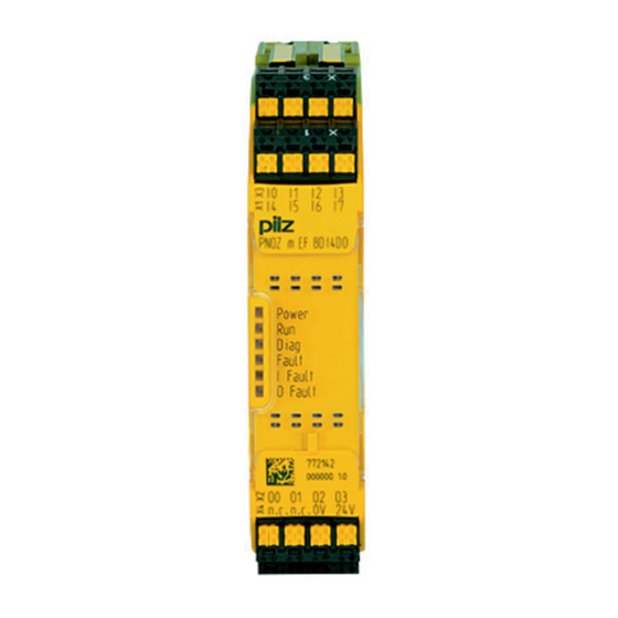
Overview Front view Front view 2200 Front view 2- Klemmenbelegung Legende Key: 0 V, 24 V: Supply connections Inputs I0 – I7 Outputs O0 – O3 LEDs: – POWER – Run – Diag – Fault – I Fault –... -
Page 11: Chapter 3 Safety
Safety Intended use 3 3 000 Safety Safety 3- 3.1 Intended use 3100 Intended use 3- Bestimmung/Gertebeschreibung_multi_Zusatz_Modul_2 The expansion module may only be connected to a base unit from the configurable control system PNOZmulti 2 (please refer to the document "PNOZmulti System Expansion"... -
Page 12: Safety Regulations
Safety Safety regulations 3.2.1 Use of qualified personnel Safety regulations 3200 Safety regulations Use of qualified personnel 3- Sich Qualif. Personal The products may only be assembled, installed, programmed, commis- sioned, operated, maintained and decommissioned by competent per- sons. A competent person is someone who, because of their training, experi- ence and current professional activity, has the specialist knowledge re- quired to test, assess and operate the work equipment, devices, systems, plant and machinery in accordance with the general standards... -
Page 13: For Your Safety
Safety Safety regulations 3.2.4 For your safety For your safety 3- Zu Ihrer Sicherheit_multi_Module The unit meets all necessary conditions for safe operation. However, you should always ensure that the following safety requirements are met: This operating manual only describes the basic functions of the unit. Information on the advanced functions can be found in the online help for the PNOZmulti Configurator and in the PNOZmulti technical cata- logue. - Page 14 Safety...
-
Page 15: Chapter 4 Function Description
Function description Device properties 4.1.1 Integrated protection mechanisms 4 4 000 Function description Function description 4- 4.1 Device properties 4100 Device properties Integrated protection mechanisms 4- Sicherheitseigenschaften_multi_allgemein The relay conforms to the following safety criteria: The circuit is redundant with built-in self-monitoring. ... - Page 16 Function description...
-
Page 17: Chapter 5 Installation
Installation General installation guidelines The unit should be installed in a control cabinet with a protection type 5 5 000 Installation Installation 5- 5.1 General installation guidelines 5100 General installation guidelines 5- Montage_multi_2_allgemein of at least IP54. Fit the safety system to a horizontal mounting rail. The venting slots must face upward and downward. -
Page 18: Dimensions
Installation Dimensions Dimensions 5200 Dimensions 5- Abmessungen... -
Page 19: Connect The Base Unit And Expansion Modules
Installation Connect the base unit and expansion modules Connect the base unit and expansion modules 5300 Connect the base unit and expansion modules 5- Montage_multi_Modul_verbind_links_mini_BA Connect the base unit and the expansion module as described in the operating instructions for the base units. ... - Page 20 Installation...
-
Page 21: Chapter 6 Commissioning
Commissioning General wiring guidelines 6 6 000 Commissioning Commissioning 6- 6.1 General wiring guidelines 6100 General wiring guidelines 6- Verdrahtung_multi_Modul The wiring is defined in the circuit diagram of the PNOZmulti Configura- tor. Note: Information given in the "Technical details" must be followed. -
Page 22: Preparing For Operation
Commissioning Preparing for operation 6.2.1 Download modified project to the PNOZmulti safety system Preparing for operation 6200 Preparing for operation Download modified project to the PNOZmulti safety system 6- Verdrahtung_multi_Modul_Betr_geaend_Projekt_BA As soon as an additional expansion module has been connected to the system, the project must be amended using the PNOZmulti Configura- tor. - Page 23 Commissioning Preparing for operation Connection examples for semiconductor outputs Redundant output Single output Single output with advanced fault de- tection* *Two loads may be connected to each safety output with advanced fault detection, even on applications in accordance with EN IEC 62061, SIL CL 3.
- Page 24 Commissioning...
-
Page 25: Chapter 7 Operation
Operation Messages 7 7 000 Operation Operation 7- 7.1 Messages 7100 Messages 7- Betrieb_Meldungen_allgemein_BA When the supply voltage is switched on, the PNOZmulti safety system copies the configuration from the chip card. The LEDs "POWER","DIAG", "FAULT", "IFAULT" and "OFAULT" light up on the base unit. - Page 26 Operation...
- Page 27 Technical details Technical details 8 8 000 Technical details Technical details 8- 8.1 Technical details 8100 Technical details 8- ][Technische Daten_multi_Basis_Multi_2 Technical details Electrical data Module's current consumption 39 mA Module's power consumption 1.0 W Infeed for Supply to the SC outputs Supply voltage 24 VDC Voltage tolerance...
- Page 28 Technical details Technical details Environmental data Rated insulation voltage 30 V Shock stress EN 60068-2-27 11 ms Mechanical data Protection type Mounting (e.g. cabinet) IP54 Housing IP20 Terminals IP20 DIN rail Top hat rail 35 x 7.5 EN 50022 Recess width 27 mm Maximum cable runs Max.
- Page 29 Technical details Technical details Safety characteristic data Unit Operating mode EN ISO 13849- EN 954-1 EN IEC 62061 PFH [1/h] EN ISO 1: 2006 Category SIL CL 13849-1: 2006 [year] Logic PL e (Cat. 4) Cat. 4 SIL CL 3 2.84E-10 Input SC inputs...
- Page 30 Technical details Permitted ambient temperature Tamb dependent on the total current Isum Permitted ambient temperature Tamb dependent on the total current Isum 8200 Permitted ambient temperature Tamb dependent on the total current Isum 8- _Dummy-Vorlage...
- Page 31 Technical details Order reference Order reference 8300 Order reference 8- Bestelldaten PNOZ m EF 8DI4DO Order reference Product type Features Order no. PNOZ m EF 8DI4DO Expansion module 772 142 Bestelldaten Zubehör Klemmen PNOZmulti 2 22_5 Order reference: Accesso- ries Product type Features Order no.
- Page 32 Technical details...
- Page 33 Contact address In many countries we are represented by our subsidiaries and sales partners. Please refer to our homepage for further details or contact our headquarters.
Need help?
Do you have a question about the PNOZmulti PNOZ m EF 8DI4DO and is the answer not in the manual?
Questions and answers