Pilz PNOZ mi1p Product Manual
Expansion modules
Hide thumbs
Also See for PNOZ mi1p:
- Operating manual (21 pages) ,
- Operating instructions manual (16 pages) ,
- Configuration manual (359 pages)
Table of Contents
Advertisement
Quick Links
Products
Expansion module for connection to a
base unit from the PNOZmulti modular
safety system
Approvals
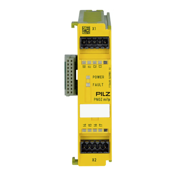
PNOZ mi1p
Block diagram
Pilz GmbH & Co. KG, Sichere Automation, Felix-Wankel-Straße 2, 73760 Ostfildern, Germany
Telephone: +49 711 3409-0, Telefax: +49 711 3409-133, E-Mail: pilz.gmbh@pilz.de
Unit features
8 inputs for connecting:
– E-STOP pushbutton
– Two-hand button
– Safety gate limit switch
– Reset button
– Light barrier
– Scanner
– Enable switch
– PSEN
– Operating mode selector switch
Can be configured in the
PNOZmulti Configurator
LED indicator for:
– Status of the PNOZmulti safety
system
Max. 8 PNOZ mi1p units can be
connected to the base unit
Test pulse outputs used to detect
shorts across the inputs
Plug-in connection terminals (either
cage clamp terminal or screw termi-
nal)
Unit description
The expansion module may only be
connected to a base unit from the
PNOZmulti modular safety system.
I0 I1
I2 I3
I4 I5
Input
The PNOZmulti modular safety system
is used for the safety-related interrup-
tion of safety circuits and is designed
for use in:
Emergency stop equipment
Safety circuits in accordance with
VDE 0113 Part 1 and EN 60204-1
Safety features
The relay conforms to the following
safety criteria:
The circuit is redundant with built-in
self-monitoring.
The safety function remains effec-
tive in the case of a component fail-
ure.
I6 I7
NSG-D-2-369-2006-02
Advertisement
Table of Contents

Subscribe to Our Youtube Channel
Related Manuals for Pilz PNOZ mi1p


Summary of Contents for Pilz PNOZ mi1p
- Page 1 PNOZmulti modular safety system. Block diagram I0 I1 I2 I3 I4 I5 I6 I7 Input Pilz GmbH & Co. KG, Sichere Automation, Felix-Wankel-Straße 2, 73760 Ostfildern, Germany NSG-D-2-369-2006-02 Telephone: +49 711 3409-0, Telefax: +49 711 3409-133, E-Mail: pilz.gmbh@pilz.de...
- Page 2 Use copper wire that can withstand 75 °C. Pilz GmbH & Co. KG, Sichere Automation, Felix-Wankel-Straße 2, 73760 Ostfildern, Germany NSG-D-2-369-2006-02 Telephone: +49 711 3409-0, Telefax: +49 711 3409-133, E-Mail: pilz.gmbh@pilz.de...
- Page 3 E-STOP without detection of shorts across contacts Example: E-STOP with detection of shorts across contacts E-STOP pushbutton Pilz GmbH & Co. KG, Sichere Automation, Felix-Wankel-Straße 2, 73760 Ostfildern, Germany NSG-D-2-369-2006-02 Telephone: +49 711 3409-0, Telefax: +49 711 3409-133, E-Mail: pilz.gmbh@pilz.de...
- Page 4 To comply with EMC requirements, the DIN rail must have a low imped- ance connection to the control cab- inet housing. Pilz GmbH & Co. KG, Sichere Automation, Felix-Wankel-Straße 2, 73760 Ostfildern, Germany NSG-D-2-369-2006-02 Telephone: +49 711 3409-0, Telefax: +49 711 3409-133, E-Mail: pilz.gmbh@pilz.de...
- Page 5 Weight with connector 130 g Order reference Type Features Order no. PNOZ mi1p Expansion module 8 inputs 773 400 Pilz GmbH & Co. KG, Sichere Automation, Felix-Wankel-Straße 2, 73760 Ostfildern, Germany NSG-D-2-369-2006-02 Telephone: +49 711 3409-0, Telefax: +49 711 3409-133, E-Mail: pilz.gmbh@pilz.de...
Need help?
Do you have a question about the PNOZ mi1p and is the answer not in the manual?
Questions and answers