Table of Contents
Advertisement
Quick Links
Advertisement
Table of Contents

Subscribe to Our Youtube Channel
Related Manuals for Inficon VGC402


Summary of Contents for Inficon VGC402
- Page 1 Artisan Technology Group is your source for quality new and certified-used/pre-owned equipment SERVICE CENTER REPAIRS WE BUY USED EQUIPMENT • FAST SHIPPING AND DELIVERY Experienced engineers and technicians on staff Sell your excess, underutilized, and idle used equipment at our full-service, in-house repair center We also offer credit for buy-backs and trade-ins •...
- Page 2 Operating Manual Incl. EC Declaration of Conformity VGC402 Two-Channel Measurement and Control Unit para VGC403 Three-Channel Measurement and Control Unit para tinb07e1-e 2011-07 Artisan Technology Group - Quality Instrumentation ... Guaranteed | (888) 88-SOURCE | www.artisantg.com...
-
Page 3: Table Of Contents
Contents Introduction 3.3.6 CONTROL ......14 3.3.7 RS232C ......14 Validity . - Page 4 5.4.1 Selection ......29 6.3.31 TEE ....... 42 5.4.2 Firmware version (Pnr) .
-
Page 5: Introduction
VGC402 respective operating manuals. 398-021 VGC403 In the following, the VGC402 or VGC403 Vacuum Gauge Controller will be referred to as «Vacuum Gauge Control- The part number can be found on the type label which is ler». attached to one side of the unit. -
Page 6: Safety
1.4 Safety 1.4.3 General safety instructions For all work you are going to do, adhere to the applicable 1.4.1 Personnel qualifications safety regulations. Also observe all safety notes given in this document and All work described in this document may only be carried forward the information to all other users of the product. -
Page 7: Disconnecting Device
WARNING Improper installation and operation data. Improper installation and operation data may damage the Vacuum Gauge Controller. Strictly adhere to the stipulated installation and operation data. 1.4.4 Disconnecting device The Vacuum Gauge Controller is equipped with a discon- necting device according to EN 61010-1. The disconnecting device is located at the back of the Vacuum Gauge Controller. -
Page 8: Technical Data
Height: 128.5 mm (3 HE) decreasing to Depth: 207 mm max. 50 % (above 40 °C) See Fig. 2-1, Indoors only Altitude max. 2000 m NN Weight VGC402: 1.04 kg Pollution degree VGC403: Protection type IP20 1.16 kg Desktop unit 2.1.3... -
Page 9: Channels
Measuring ranges Sensor dependent 2.3.1 Sensor connections Error of measurement Gain error: ≤ 0.005 % FS Number of channels VGC402: 2 VGC403: 3 Offset error: ≤ 0.01 % FS Sensor connections per RJ45 (FCC 68) channel D-Sub, 15 pins, female... -
Page 10: Switching Function Relay
2.4.1 Switching function relay 2.5.2 Recorder output Contact type Change-over contact, float- Number Voltage range 0…10 VDC Load (ohmic) Max. 60 VDC, 0.5 A Resolution 1 mV Max. 30 VAC, 1 A Accuracy ± 20 mV Lifetime Mechanical: cycles 3300 Ω Internal resistance Electrical: Relation between... -
Page 11: Installation
Installation 3.1 Unpacking Turn the Vacuum Gauge Controller upside down as shown in Fig. 3-1, Visually inspect the transport packaging for signs Push the supplied rubber strip onto the lower edge of external damage of the front panel Unpack the Vacuum Gauge Controller and put the Stick the supplied rubber feet to the bottom of the packaging material aside casing... -
Page 12: Mounting The Unit In A Rack
3 (Pos. C) is not available in the The Vacuum Gauge Controller is designed for installation VGC402. into a rack chassis adapter according to DIN 41 494 (19", 3 HE). For this purpose, 4 collar screws and 4 plastic sleeves are supplied with the unit. -
Page 13: Mains Connection
3.3.2 Mains connection 3.3.3 Ground The mains connection (Fig. 3-4, 11, Pos. G) is The ground screw (Fig. 3-4, 11, Pos. I) can be used to designed for a mains cable which contains a European connect the Vacuum Gauge Controller with the protective appliance connector on the device side. -
Page 14: Relay
Pin assignment CAUTION Improper sensor. Sensors which are not designed for use with the Vacuum Gauge Controller may damage the unit. Operate the Vacuum Gauge Controller with proper sensors only. See Chapter 2.3.1 Sen- Fig. 3-8 RELAY appliance socket (D-Sub, 25-pin) sor connections, 1 GND 14 Error make contact (NO) -
Page 15: Control
3.3.6 CONTROL 3.3.7 RS232C The CONTROL connection (Fig. 3-4, 11, Pos. D) con- The RS232C serial interface (Fig. 3-4, 11, Pos. F) tains the following signal pins: allows remote control of the unit via a computer or a ter- minal. See Chapter 6 Computer interface, •... -
Page 16: Operation
Fig. 4-1, 15 shows the front panel of the VGC403. The pressure unit: mbar, Torr, Pa, or Micron. VGC402 is not equipped with the switching points SP5 and SP6 (Pos. A) and the display for the channel 3 (Pos. Channels There is a separate display area for each of the available channels (Pos. -
Page 17: Switching On And Off
4.2 Switching on and off 4.3 Operating modes The Vacuum Gauge Controller can be set to one of the 4.2.1 Switching on following operating modes: Switch the mains switch on. See Fig. 3-4, Measurement mode Pos. H. The measurement mode is the standard operating mode. After switching on, the Vacuum Gauge Controller will per- It displays the pressure readings of the sensors. -
Page 18: Measurement Mode
4.4 Measurement mode 4.4.3 Control button functions 4.4.3.1 Selecting a channel 4.4.1 Selection Press the CH button The Vacuum Gauge Controller automatically selects the measurement mode after it has been switched on. para When the unit is set to the parameter mode, it will auto- matically return to the measurement mode if no button is pressed for 10 seconds. - Page 19 4.4.3.4 Switching degas function on 4.4.3.7 Identifying a sensor The degas function of the following sensors can be Keep the UP and DOWN buttons pressed for switched on manually: BPG, BCG. approximately 1 second Press the CH button to select the required channel para Keep the UP button pressed for approximately 1 second.
-
Page 20: Parameter Mode
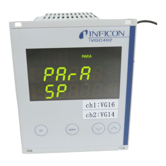
4.5 Parameter mode Parameter Parameter group 4.5.1 Selection PArA Pressing the PARA button switches from the measure- dt-C tESt ment mode to the parameter mode. The PARA indicator tr-L is illuminated. rA-t When the unit is set to the parameter mode, it will auto- EP-t matically return to the measurement mode if no button is EE-t... -
Page 21: Basic Operation
4.5.3 Basic operation Starting at the measurement menu, you can select and modify a specific parameter as follows: Press the CH button to select the required channel. (This is only necessary if you want to modify a sen- sor parameter.) Press the PARA button •... -
Page 22: Parameter
Behaviour of a switching function when the pressure changes Switching functions Pressure The VGC402 is equipped with four relays which switch in Time dependance of the measured pressure. The relay con- make contact (normally open) tacts are potential-free and can be used for switching via common contact the RELAY connection. -
Page 23: Configuring Switching Functions
5.1.2 Configuring switching functions 5.1.3 Adjustment range Prerequisite: The parameter group SP-P is selected Adjustment range of the lower threshold value Press the PARA button to select the required The lower threshold value of a switching function can be parameter set in the following pressure range: •... -
Page 24: Sensor Parameters (Para Sen)
5.2 Sensor parameters (PArA SEn) FASt Fast. The Vacuum Gauge Controller responds quickly to There is an individual set of sensor parameters for each signal changes. This makes it rather sensitive to signal channel. Select the required channel before you change noise. -
Page 25: Gas Type (Gas)
5.2.2 Gas type (GAS) • 0.01 mbar • 0.01 Torr, 0.02 Torr, 0.05 Torr Sensors are normally calibrated for a measurement in • 0.10 mbar, 0.25 mbar, 0.50 mbar nitrogen or in air. The GAS parameter is used to configure •... -
Page 26: Degas Function (Degas)
Adjusting the zero point of a digital CDG Hot start. The sensor automatically switches on when the Select the oFS parameter unit is switched on. After a power failure the measure- Keep the DOWN button pressed for approximately ment will be resumed automatically. 2 seconds •... -
Page 27: Switch-Off Threshold (T-Off)
off when the pressure on channel 2 exceeds the switch- Display Significance off threshold. Range extension: CH 3 Display down to 5 × 10 • mbar By channel 3. This setting is only available if the unit is • Setpoint adjustment range equipped with three channels. -
Page 28: General Parameters (Para Gen)
5.3 General parameters (PArA NOTE: The diGit parameter has no effect on CDG sensors. GEn) NOTE: These parameters are used for general configuration of When PrE is enabled, the display of PSG and PCG the unit. The parameters affect all channels. gauges in the pressure range p <... - Page 29 LoG +0 Logarithmic representation of the entire measuring Logarithmic representation of a part of the measurement range. range (2.5 V/decade). Sensor Pressure (in mbar) Sensor Pressure (in mbar) p = 10^[U/(10/7) - 4] All types p = 10^[U/(10/4) - 4] p = 10^[U/(10/7) - 4] LoG +3 Logarithmic representation of a part of the measurement...
-
Page 30: Error Signal Relay (Err-R)
5.4 Test parameters (PArA tESt) Sensor Pressure (in mbar) This parameter group is intended for test and service pur- All types p = U/10 * 10 poses. It is used to examine additional system data, to set basic system parameters, and to check individual system functions. -
Page 31: Torr Lock (Tr-L)
«Torr» can- A four-digit checksum is displayed. not be selected. See Chapter 5.3.1 Unit of measurement (unit), Tab. 5-16 EPROM test Please contact your local INFICON service center if the Display Significance test fails repeatedly. Unit of measurement «Torr» can be 5.4.8... -
Page 32: A/D Converter Id (Ad-I)
5.4.11 A/D converter ID (Ad-i) The test starts as soon as the rS-t parameter has been selected. You may e.g. use a terminal program and input For each channel, display a signal (in volts) which is characters via the keyboard. Each of the input characters caused by a resistor inside the connected sensor. -
Page 33: Computer Interface
Computer interface 6.1 Basics Term Value Significance <CR> Carriage return. Carriage 6.1.1 Connection return. The Vacuum Gauge Controller is able to communicate <NAK> Negative acknowledge. with a computer via a serial interface (RS232C). The con- Negative acknowledge. nection socket and the required connection cable are described in Chapter 3.3.7 RS232C, Tab. -
Page 34: Receiving (Unit --> Host)
S: Mnemonic [parameters]<CR>[<LF>] S: <ENQ> R: <ACK><CR><LF> or <NAK><CR><LF> R: 0,9.0000E-01,2.2000E+00<CR><LF> Setting the filter 6.2.3 Receiving (Unit --> Host) S: FIL,1,2,1<CR>[<LF>] The Host may request data from the unit. To this end the Host first sends a message which describes what kind of R: <ACK><CR><LF>... -
Page 35: Mnemonics
6.3 Mnemonics Mnemonic Significance Pirani range extension. 6.3.1 Overview Pressure sensors. Pressure read- Mnemonic Significance ings of all sensors. Analog output mode. Characteristic Reset. Reset the serial interface. curve of the recorder output. Save parameters to EEPROM. Baud rate. Transfer rate of the Sensor 1 control. -
Page 36: Aom
6.3.2 Parameter Significance Analog output mode. Characteristic curve of the recorder output. See Chapter 5.3.5 Recorder output (Ao), Transfer rate S: AOM[,a,b]<CR>[<LF>] 9600 baud (default) 1 = 19200 Baud R: <ACK><CR><LF> 2 = 38400 Baud S: <ENQ> R: a,b<CR><LF> NOTE: The acknowledgement of the BAU command will al- ready be sent with the changed transfer rate. -
Page 37: Cor
6.3.5 Parameter Significance Correction factor. See Chapter 5.2.2 Gas type (GAS), Sensor 1 S: COR[,a.aa,b.bb,c.cc]<CR>[<LF>] 0 = Degassing off (default) 1 = Degassing on R: <ACK><CR><LF> Sensor 2 S: <ENQ> (see above) R: a.aa,b.bb,c.cc<CR><LF> NOTE: Parameter Significance The degas function is switched off automatically af- ter 3 minutes. -
Page 38: Eum
6.3.12 FSR bined by the logical operator OR. Example: 1001 = Device error and syntax error. Full scale range. Full scale range of linear sensors (CDG). See Chapter 5.2.3 Measuring range (FS), 6.3.10 EUM S: FSR[,a,b,c]<CR>[<LF>] Switch the emmision. See Chapter 5.2.10 Emission R: <ACK><CR><LF>... -
Page 39: Fum
6.3.13 FUM 6.3.15 HVC Select the filament. See Chapter 5.2.11 Filament selec- High vacuum circuit on/off. Switch the high vacuum circuit tion (FiL), of sensors on/off. See Chapter 4.4.3 Control button func- tions, S: FUM[,a,b,c]<CR>[<LF>] S: HVC[,a,b,c]<CR>[<LF>] R: <ACK><CR><LF> R: <ACK><CR><LF> S: <ENQ>... -
Page 40: Ofc
S: LOC[,a]<CR>[<LF>] Parameter Significance R: <ACK><CR><LF> ±b.bbbbE±bb Offset value of sensor 2 in current S: <ENQ> unit of measurement (see above) R: a<CR><LF> ±c.ccccE±cc Offset value of sensor 3 in current unit of measurement (see above) Parameter Significance 6.3.20 PNR Parameter setup lock Program number. -
Page 41: Pre
6.3.22 PRE Parameter Significance Pirani range extension. See Chapter 5.2.12 Pirani range ±f.ffffE±ff Pressure reading of sensor 3 in the extension (PrE), current unit of measurement S: PRE[,a,b,c]<CR>[<LF>] R: <ACK><CR><LF> 6.3.24 RES S: <ENQ> Reset. Reset the serial interface. R: a,b,c<CR><LF> Deletes the input buffer. -
Page 42: Sc1
6.3.27 SP1 Parameter Significance Setpoint 1. Switching function 1. See Chapter 5.1 Switch- ing function parameters (PArA SP), Save parameters S: SP1[,a,b.bbbbE±bb,c.ccccE±cc]<CR>[<LF>] 0 = Save default parameters 1 = Save user parameters R: <ACK><CR><LF> S: <ENQ> NOTE: Parameters which have been changed manually R: a,b.bbbbE±bb,c.ccccE±cc<CR><LF>... -
Page 43: Tad
Parameter Significance Parameter Significance Status of switching function 6 Test status (see above) 0 = Off 1 = On 6.3.29 TAD Test A/D converter. Test the A/D converter. See 6.3.31 TEE Chapter 5.4.10 A/D converter signal (Ad-S), 30 and Chapter 5.4.11 A/D converter ID (Ad-i), Test EEPROM. -
Page 44: Tid
6.3.33 TID Parameter Significance Transmitter identification. Sensor identification. See Chapter 4.4.3.7 Identifying a sensor, Test status S: TID<CR>[<LF>] 0 = Off 1 = On R: <ACK><CR><LF> Relay status S: <ENQ> 00 = All relays off R: a,b,c<CR><LF> 01 = Switching function 1 relay on 02 = Switching function 2 relay on Parameter Significance... -
Page 45: Tlc
6.3.36 TLC Parameter Significance Torr lock. See Chapter 5.4.4 Torr lock (tr-L), Unit of measurement S: TLC[,a]<CR>[<LF>] 0 = mbar/bar (default) R: <ACK><CR><LF> 1 = Torr S: <ENQ> 2 = Pascal 3 = Micron R: a<CR><LF> 6.3.40 WDT Parameter Significance Watchdog control. -
Page 46: Maintenance And Service
PC screen. After approximately 1 minute the trans- firmware version, e.g. for using a new sensor type, please fer is completed. contact your local INFICON service center. You may also visit our website www.inficon.com where firmware updates are available for download. -
Page 47: Calibration
The Vacuum Gauge Controller can only measure with 7.3.3 high accuracy when it is calibrated precisely. The Vac- uum Gauge Controller is calibrated by INFICON before it Calibration factor. Calibration factor of the A/D converter. is shipped. Normally there is no need to change the cali- The command is intended for service technicians of INF- bration data. - Page 48 The calibration offset of the respective channel is deter- mined and stored in the EEPROM. Calibration factor Remove the D-Sub plug with the wire strap from the sensor connection of the respective channel Connect pin 2 (Signal) and pin 12 (Signal-GND) of a 15-pin D-Sub plug with a high-precision voltage source.
-
Page 49: Troubleshooting
If the fault persists even after the message has been the respective sensor. acknowledged several times and/or the sensor has been Press PARA to acknowledge. If the exchanged, please contact your local INFICON service cause has not been removed, then center. noSEn or noid will be displayed. -
Page 50: Storage And Disposal
9.1 Packaging Please keep the original packaging. The packaging is required for storing the Vacuum Gauge Controller and for shipping it to an INFICON service center. 9.2 Storage The Vacuum Gauge Controller may only be stored in a dry room. The following requirements must be met: Ambient temperature -20…+60 °C... -
Page 51: Appendix
Appendix Conversion tables Weights = ... slug 6.852 × 10 2.205 35.27 3.108 × 10 0.454 28.35 × 10 62.5 × 10 1.943 × 10 slug 14.59 32.17 514.8 Pressure = ... Pa (= N/m mbar Torr (= mm Hg) psi (= lb/in 0.987 ×... -
Page 52: Default Parameters
[11] Operating Manual Bayard-Alpert Pirani Gauge BPG400 The operating manuals listed below can be downloaded tina03e1 from the website www.inficon.com in the PDF file format. INFICON AG, LI–9496 Balzers, Liechtenstein Operating Manual [12] Operating Manual Pirani Standard Gauge PSG400, PSG400-S... -
Page 53: Index
MPG400, MPG401 tina48e1 INFICON AG, LI–9496 Balzers, Liechtenstein A/D converter calibration ..... . . 46 A/D converter test ......30... - Page 54 Switching the degas function on ....18 Measuring range ......24 EC Declaration of Conformity .
- Page 55 Filament selection ......26 Warranty ........4 Gas type .
-
Page 56: Etl Certification
We, INFICON, hereby declare that the equipment men- tioned below complies with the provisions of the Directive relating to electrical equipment designed for use within The products VGC402 and VGC403 comply with the certain voltage limits 2006/95/EC and the Directive relat- requirements of the following standards: ing to electromagnetic compatibility 2004/108/EC. - Page 57 LI-9496 Balzers Original: tinb07d1-e (2011-07) Liechtenstein +423 / 388 3111 +423 / 388 3700 t i nb07e1- e reachus@inficon.com www.inficon.com Artisan Technology Group - Quality Instrumentation ... Guaranteed | (888) 88-SOURCE | www.artisantg.com...
- Page 58 Artisan Technology Group is your source for quality new and certified-used/pre-owned equipment SERVICE CENTER REPAIRS WE BUY USED EQUIPMENT • FAST SHIPPING AND DELIVERY Experienced engineers and technicians on staff Sell your excess, underutilized, and idle used equipment at our full-service, in-house repair center We also offer credit for buy-backs and trade-ins •...
Need help?
Do you have a question about the VGC402 and is the answer not in the manual?
Questions and answers