Norac UC5 Installation Manual
Spray height controller.
john deere gs2 2600 and 1800
all pull types display kit
Hide thumbs
Also See for UC5:
- Operator's manual (68 pages) ,
- Installation manual (50 pages) ,
- Instruction manual (35 pages)

Subscribe to Our Youtube Channel
Related Manuals for Norac UC5


Summary of Contents for Norac UC5
- Page 1 Spray Height Controller John Deere GS2 2600 and 1800 All Pull Types Display Kit Installation Manual GS2-PT01...
- Page 2 Display Kit) NOTICE: NORAC Systems International Inc. reserves the right to improve products and their specifications without notice and without the requirement to update products sold previously. Every effort has been made to ensure the accuracy of the information contained in this...
-
Page 3: Table Of Contents
3.3 ITEM C30: 43250-06 – CABLE UC5 BATTERY PIGTAIL ............. 8 3.4 ITEM C41: 43220-03 - CABLE UC5 NETWORK 14 AWG - 3M............8 3.5 ITEM C40: 43260-02 – CABLE UC5 CAN BUS VT JD GS2 ............9 APPENDIX A: ALTERNATE CONFIGURATION ..........10... -
Page 4: Introduction
UC5 Spray Height Control Installation Manual. This manual provides instructions to interface the UC5 Control Module to the John Deere GS2 2600 and 1800 Displays. For installation of the rest of the UC5 Spray Height Control System please refer to the sprayer specific manual provided with the kit. -
Page 5: Installation
2 Installation The following instructions are for installation on a pull type sprayer. On a pull type sprayer if the CAN-bus and power supply are located on the sprayer, the control module may also be installed on the sprayer (Section 2.2). This type of installation would eliminate the need for a cable across the hitch. -
Page 6: Control Module On Sprayer
Control Module on Sprayer 1. Securely mount the control module (E01) on the sprayer near the CAN-bus connection. 2. Tee the CAN-bus interface cable (C40) in to the John Deere CAN-bus. Connect the 6 pin Deutsch plug on cable C40 to the end of the control module with only one Deutsch connector. -
Page 7: Switch Box Installation
Switch Box Installation 1. This step of the installation assumes that the input module and all required cables are installed. 2. Disconnect cable C20 (Thru 2 connector) from the Input Module (E03). Remove the wedge from the face of the 12 pin Deutsch plug. The wedge is removed by inserting a small flat implement underneath the wedge and lifting it up. -
Page 8: Cable Drawings
3 Cable Drawings ITEM C25: 44602-01 – SWITCH REMOTE HAND CONTROL... -
Page 9: Item C26: 43240-26 - Cable Uc5 Switch Box
ITEM C26: 43240-26 – CABLE UC5 SWITCH BOX... -
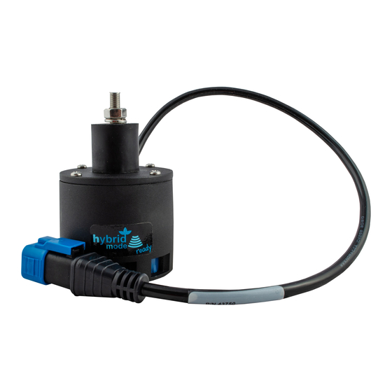
Page 10: Item C30: 43250-06 - Cable Uc5 Battery Pigtail
ITEM C30: 43250-06 – CABLE UC5 BATTERY PIGTAIL ITEM C41: 43220-03 - CABLE UC5 NETWORK 14 AWG - 3M... -
Page 11: Item C40: 43260-02 - Cable Uc5 Can Bus Vt Jd Gs2
ITEM C40: 43260-02 – CABLE UC5 CAN BUS VT JD GS2... -
Page 12: Appendix A: Alternate Configuration
Appendix A: Alternate Configuration If your sprayer has European style slant control, you will need to reconfigure the switch box as shown below. This is only required for sprayer types which are driving the slant output from the Input Module. Reconfigure the pins on cable C26 and C20 as follows: Normal Configuration European Style Slant Configuration Function... - Page 13 Canada NORAC Systems International Inc. Phone: (+1) 306 664 6711 Toll Free: 1 800 667 3921 Shipping Address: 3702 Kinnear Place Saskatoon, SK S7P 0A6 United States NORAC, Inc. Phone: (+1) 763 786 3080 Toll Free: 1 866 306 6722...
Need help?
Do you have a question about the UC5 and is the answer not in the manual?
Questions and answers