Norac UC5 Operator's Manual
Spray height controller
Hide thumbs
Also See for UC5:
- Operator's manual (68 pages) ,
- Installation manual (50 pages) ,
- Instruction manual (35 pages)
Table of Contents
Advertisement
Quick Links
Advertisement
Table of Contents

Related Manuals for Norac UC5


Summary of Contents for Norac UC5
- Page 1 Spray Height Controller Operator Manual...
- Page 2 Reorder P/N: UC5-BC-MANUAL Rev A (UC5 Operator Manual) NOTICE: NORAC Systems International Inc. reserves the right to improve products and their specifications without notice and without the requirement to update products sold previously. Every effort has been made to ensure the accuracy of the information contained in this...
-
Page 3: Table Of Contents
7.5 Sensing Further Ahead of the Boom ......................10 7.6 Height Sensor Capabilities and Limitations ...................10 7.7 Soil Mode and Crop Mode ........................11 8 SYSTEM SETUP .......................12 8.1 Navigating to the UC5 Setup Menu .......................12 8.2 Automatic System Setup ........................14 8.3 Retune ..............................19 8.4 Manual Setup............................22... -
Page 4: Introduction
1 Introduction Congratulations on your purchase of a NORAC UC5 Spray Height Control System. This system has an unmatched reputation within the industry for boom protection and spray height accuracy. When properly used, the UC5 Spray Height Control system provides protection from boom damage as well as improving sprayer efficiency and chemical performance by ensuring correct chemical application. -
Page 5: Safety Precautions
2 Safety Precautions Always ensure that the UC5 Spray Height Control system is powered down or in manual mode: • Before leaving the operator’s seat. • While the machine is not moving. • When transporting the machine. Before working on any part of the booms: •... -
Page 6: Key Features
Improved Reliability • Each UC5 system is installed in a way to leave the sprayer hydraulics operational. • This means that if a cable is damages or a UC5 component is removed the sprayer remains functional. Ease of Use •... -
Page 7: System Description
4 System Description General UC5 System Layout Figure 1: General UC5 System Layout (Self Propel Type) Figure 2: General UC5 System Layout (Pull Type) -
Page 8: Height Sensors
• Height sensors use an ultrasonic signal to measure distance to the ground or crop canopy. • Generally there is a sensor mounted to the outer part of each boom tip, and another sensor mounted to the center section. Refer to the UC5 installation manual for more detail. Roll Sensors •... -
Page 9: System Operation
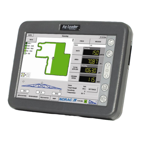
• To change between automatic and manual mode, press the button in the lower right corner of the terminal. When the UC5 Height Control System is in automatic mode, arrows will appear on the screen above or below the boom sections. These arrows indicate the UC5 system is making a correction to part of the boom in the displayed direction. - Page 10 By pressing and holding the main lift switch the system will go into manual mode. On the right side of the screen, the NORAC UC5 settings are displayed. To change these settings, click the settings button to display the boom height control options screen.
-
Page 11: Uc5 Kit Options
6 UC5 Kit Options Severe Terrain Kit • Additional sensors may be added to improve boom protection and system performance. • This is more suitable for larger booms and in severe terrain conditions. • Figure 6 illustrates the benefits of the severe terrain kit. -
Page 12: Understanding The Uc5 System
• The first is for the operator to recognize these situations before they occur and manually raise the boom to a safe height. • The second is to add the NORAC Roll Control option, if one is available for the specific sprayer. This will compensate for the sprayer roll and make the required corrections faster and smoother, allowing for increased boom protection and higher spraying speeds. -
Page 13: Sensing Further Ahead Of The Boom
• In order to optimize sensor performance, the UC5 sensor has a minimum distance that it will read (also known as the blanking range). As a result, the UC5 sensor is designed to ignore targets closer than 8 inches (20cm) from the bottom of the sensor housing. -
Page 14: Soil Mode And Crop Mode
Soil Mode and Crop Mode • Height sensors use “smart sensor” technology, which take measurements from both the top of the crop canopy and from the soil surface. This allows the user to select either “Crop” or “Soil” mode. • In “Soil” mode the target height is measured from the soil to the sprayer nozzle. In “Crop” mode the target height is measured from the crop canopy to the sprayer nozzle. -
Page 15: System Setup
After the NORAC unlock code has been installed on the Ag Leader® InSight™ display, the UC5 functionality must be tested and the software must be tuned for the sprayer. There are two methods to setup the UC5 system. The recommended way is to use the automatic system setup as shown in Section 8.2. - Page 16 In the implement list select your sprayer and then click on the NORAC UC5 setup button. Make sure the enable boom height checkbox is checked. This is the NORAC UC5 setup menu. The following sections will describe the features found within this menu.
-
Page 17: Automatic System Setup
• Cycle all boom sections up and down manually for five minutes to warm the oil. • For pull-type sprayers, ensure any hydraulic flow controls are adjusted for normal field operation. • Changing the hydraulic flow controls after or during the system setup will affect the UC5 performance. - Page 18 Navigate to the UC5 setup screen. When the UC5 setup window is displayed, make sure the drop down box under the NORAC logo is populated. Select automatic setup. Select the sprayer make and model from the drop down boxes. Then click the ok button.
- Page 19 A list of precautions will be displayed on the terminal. It is very important that you read these precautions and follow them. Once you have read the precautions, click the proceed button. A list of connected modules will be displayed. Make sure the modules match your system modules.
- Page 20 You will then be instructed to place your booms so the nozzles are 35” (90 cm) from the ground. Adjust the distance from the nozzle to the ground directly beneath. Ensure you are over bare, flat soil. 35” 90 cm When the measured distance is 35”...
- Page 21 If you accidentally release the button, press and hold the proceed button to resume. When the setup is finished the terminal will instruct you to press cancel to complete the automatic setup. Your NORAC UC5 system is now configured and ready for operation.
-
Page 22: Retune
Retune On occasion it is necessary to recalibrate the NORAC UC5 Height Control System. You may want to perform a retune when: • A hydraulic solenoid has been changed. • A hydraulic pump has been changed or adjusted. • A different tractor has been connected to the sprayer. - Page 23 A list of connected modules will be displayed. Make sure the modules match your system modules. If the list of modules matches the currently installed modules, press the proceed button. You will then be instructed to hold the proceed button. Continue holding proceed while each boom section is moved.
- Page 24 If you accidentally release the button, press and hold the proceed button to resume. When the setup is finished the terminal will instruct you to press cancel to complete the automatic setup. Your NORAC UC5 system is now configured and ready for operation.
-
Page 25: Manual Setup
Manual Setup The UC5 Height Control system will not operate in automatic mode until the system has been configured. It is recommended that the automatic system setup be used, but if necessary a manual system setup may be used. The manual system setup involves setting up each sensor, valve output and remote switch input. - Page 26 Navigate to the UC5 setup screen. When the UC5 setup window is displayed, make sure the drop down box under the NORAC logo is populated. Select sensors and valve drivers. Select the sensor tab. This screen displays a list of currently configured sensors.
- Page 27 Select the sensor position that you are configuring and select the appropriate serial number from the second drop down menus. Select accept to confirm. Continue this for each of the sensors, if necessary. To set the sensor height, select the appropriate sensor.
- Page 28 8.4.2 Manual Valve Setup Each valve must be setup and tuned correctly for optimum performance from the NORAC UC5 Spray Height Controller. When setting up the valves, the sprayer booms must have room to move in their full range of motion. Make sure there are no obstructions, such as power lines, that the booms may come into contact with.
- Page 29 Select the function that you are configuring and the appropriate driver (Serial/Output) from the drop-down menus. There are two sources of drivers, the input module and valve module. You must choose the correct module and correct output for the valves to work correctly. A list with a default setup is shown in Table 1.
- Page 30 8.4.3 Manual Valve Tuning Each valve has two settings; a deadzone and gain setting. The deadzone relates to the smallest amount of movement the valve can produce. The gain relates to the maximum speed at which the valve can move the boom function. A deadzone and gain parameter exists for each valve.
- Page 31 Manual Deadzone Calibration In the valve tab select the function that you wish to calibrate. Push the deadzone button. Press and hold manual test. Continue to hold it until the boom stops moving and the live reading of the distance travelled stabilizes. When properly tuned, the distance travelled should be 1-2 inches (2- 5cm).
- Page 32 Automatic Gain Calibration Before tuning the gain setting, the deadzone for that function must be tuned. If the deadzone tuning has not been completed, follow the instructions for tuning a deadzone. In the valve tab, select the function that you wish to calibrate. Push the gain button.
- Page 33 Manual Gain Calibration This test will drive the boom at full speed in the selected direction for one second. Make sure the boom has full range of movement and if driving the boom down, make sure it is not close to the ground.
- Page 34 In the valve tab select the function that you wish to calibrate. Push the gain button. Press and hold the manual test button. Continue to hold it until the boom stops moving and the live height reading stabilizes. Displayed is the boom speed, in inches/second.
- Page 35 8.4.4 Remote Switch Setup Remote switches allow manual override of the UC5 system. Depending on the input, this may cause a complete override or a partial override of UC5 automatic control. Each of the UC5 functions requires a manual override.
- Page 36 Select the function that you are setting up from the drop down menu, and then select the appropriate switch from the serial/output box. A list with the default input channels is shown in Table 3 Select accept to set the settings. Continue this for each of the sprayer functions, if necessary.
-
Page 37: Maintenance
9 Maintenance The UC5 Height Control System requires very little maintenance, but there are a few procedures that will ensure the system continues to work correctly for many years. Before each day: • It is highly recommended that the sprayer friction pads are greased. This will ensure the boom is pivoting separately from the sprayer. - Page 38 Canada NORAC Systems International Inc. Phone: (+1) 306 664 6711 Toll Free: 1 800 667 3921 Shipping Address: 3702 Kinnear Place Saskatoon, SK S7P 0A6 United States NORAC, Inc. Phone: (+1) 763 786 3080 Toll Free: 1 866 306 6722...
Need help?
Do you have a question about the UC5 and is the answer not in the manual?
Questions and answers