Table of Contents
Advertisement
Quick Links
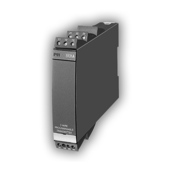
5 1 3 1
2 - W i r e P r o g r a m m a b l e
T r a n s m i t t e r
N o . 5 1 3 1 V 1 0 4 - I N ( 0 9 2 3 )
F r o m s e r . n o . 0 4 0 1 1 2 0 0 1
16
S I G N A L S T H E B E S T
2-WIRE
PROGRAMMABLE TRANSMITTER
PRetrans type 5131
Table of contents
Warnings ............................................................................ 18
Safety instructions .............................................................. 20
EC Declaration of Conformity ............................................ 22
How to dismantle SYSTEM 5000 ....................................... 23
Application ......................................................................... 24
Technical characteristics .................................................... 24
Input types ......................................................................... 24
Output ................................................................................ 25
Sensor error detection ....................................................... 25
Configuration ...................................................................... 25
Electrical specifications ...................................................... 26
Order .................................................................................. 30
5131 connection to Loop Link ........................................... 31
Selection of input type ....................................................... 31
Block diagram .................................................................... 32
Australia / Asia Pacific Office
Tel +61 (0)282 442 363
Fax +61 (0)294 751 278
info@omniinstruments.com.au
www.omniinstruments.com.au
UK / Europe Office
Tel: +44 (0)845 9000 601
Fax: +44 (0)845 9000 602
info@omniinstruments.co.uk
www.omniinstruments.co.uk
USA / Canada Office
Tel +1-866-849-3441
Fax +1-866-628-8055
info@omniinstruments.net
www.omniinstruments.net
17
Advertisement
Table of Contents

Summary of Contents for PR electronics PRetrans 5131
-
Page 1: Table Of Contents
2-WIRE PROGRAMMABLE TRANSMITTER PRetrans type 5131 Table of contents Warnings ................18 Safety instructions .............. 20 EC Declaration of Conformity ..........22 How to dismantle SYSTEM 5000 ........23 Application ................. 24 Technical characteristics ............ 24 Input types ................. 24 Output ................ -
Page 2: Warnings
General mounting, connection and disconnection of wires. Troubleshooting the module. Repair of the module and replacement of circuit breakers must be done by PR electronics A/S only. WARNING! SYSTEM 5000 must be mounted on DIN rail according to DIN 46277. -
Page 3: Safety Instructions
LIABILITY: Class II. To the extent the instructions in this manual are not strictly observed, the customer cannot advance a demand against PR electronics A/S that would MOUNTING: otherwise exist according to the concluded sales agreement. Only technicians who are familiar with the technical terms, warnings, and instructions in the manual and who are able to follow these should connect the module. -
Page 4: Ec Declaration Of Conformity
HOW TO DISMANTLE SYSTEM 5000 As manufacturer First, remember to demount the connectors with hazardous voltages. By lifting PR electronics A/S the bottom lock, the module is detached from the DIN rail as shown in picture 1. Lerbakken 10 Then, by lifting the upper lock and pulling the front plate simultaneously the PCB is removed as shown in picture 2. -
Page 5: Application
This means that one channel can work as for instance a temperature The transmitter is configured to the present task by way of a and PR electronics transmitter and the other can work as an isolation amplifier. Measurement range, A/S’... -
Page 6: Electrical Specifications
ELECTRICAL SPECIFICATIONS: Basic values Basic Temperature Specifications range: Input type accuracy coefficient -20°C to +60°C ≤ ±4 µA ≤ ±0.4 µA/°C Common specifications: ≤ ±10 µV ≤ ±1 µV/°C Volt Supply voltage ..........7.5...35 VDC ≤ ±0.2°C ≤ ±0.01°C/°C Fuse ............. 50 mA SB / 250 VAC ≤... - Page 7 Electrical specifications, temperature input: Electrical specifications, mA / V / mV input: TC input: Current input: Measurement range ........0...100 mA Min. Max. Min. Min. measurement range (span) ....4 mA Type temperature temperature span Standard Max. offset ..........50% of selec. max. value +400°C +1820°C 200°C...
-
Page 8: Order
Ex / I.S. data: 5131 CONNECTION TO LOOP LINK: ............... : 250 V ..............: 8.0 VDC ..............: 10 mADC ..............: 20 mW Receiving Loop communication Disconnect when "on line" equipment ..............: 200 mH loop communication is used Black Red supp .............. -
Page 9: Block Diagram
BLOCK DIAGRAM: Displays Programmable displays with a wide selection of inputs and outputs for display of temperature, volume and weight, etc. Feature linearisation, scaling, and difference measurement functions for programming via PReset software. Ex interfaces Interfaces for analogue and digital signals ®...


Need help?
Do you have a question about the PRetrans 5131 and is the answer not in the manual?
Questions and answers