Advertisement
Available languages
Available languages
Isolation
Galvanic isolators for analogue and digital
signals as well as HART
®
signals. A wide product range
with both loop-powered and universal isolators featuring
linearisation, inversion, and scaling of output signals.
Displays
Programmable displays with a wide se-
lection of inputs and outputs for display of temperature,
volume, weight, etc. Feature linearisation, scaling, and
difference measurement functions for programming via
PReset software.
Ex barriers
Interfaces for analogue and digital signals
as well as HART
signals between sensors / I/P convert-
®
ers / frequency signals and control systems in Ex zone 0,
1 & 2. Feature options such as mathematical functions
and 2 wire transmitter interfaces.
Temperature
A wide selection of transmitters for DIN
form B mounting and DIN rail modules with analogue
and digital bus communication ranging from application-
specifi c to universal transmitters.
Backplane
Flexible motherboard solutions for sys-
tem 5000 modules. Our backplane range features fl exible
8 and 16 module solutions with confi guration via PReplan
8470 – a PC program with drop-down menus.
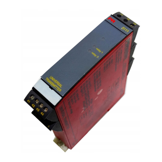
5 1 1 1
U n i v e r s a l
T r a n s m i t t e r
N o . 5 1 1 1 V 1 0 6 - I N ( 0 6 0 6 )
F r o m s e r . n o . 0 4 0 0 2 0 8 0 1
S I G N A L S T H E B E S T
Side 1
DK
Page 29
UK
Page 57
FR
Seite 85
DE
Advertisement
Chapters

Subscribe to Our Youtube Channel
Related Manuals for PR electronics 5111


Summary of Contents for PR electronics 5111
- Page 1 Isolation Galvanic isolators for analogue and digital signals as well as HART ® signals. A wide product range with both loop-powered and universal isolators featuring linearisation, inversion, and scaling of output signals. Displays Programmable displays with a wide se- lection of inputs and outputs for display of temperature, volume, weight, etc.
-
Page 2: Table Of Contents
UNIVERSAL TRANSMITTER PRETRANS TYPE 5111 INDHOLDSFORTEGNELSE Advarsler ........2 Sikkerhedsregler . -
Page 3: Sikkerhedsregler
Trekant med udråbstegn: Advarsel / krav. Hændelser der kan PR electronics A/S, Lerbakken 10, 8410 Rønde, Danmark tlf: +45 86 37 26 77. føre til livstruende situationer. Installation og tilslutning af modulet skal følge landets gældende regler for instal- lation af elektrisk materiel bl. -
Page 4: Overensstemmelseserklæring
I det omfang, instruktionerne i denne manual ikke er nøje overholdt, vil kunden ATEX-certifikat: DEMKO 01ATEX130321 ikke kunne rette noget krav, som ellers måtte eksistere i henhold til den indgåede salgsaftale, mod PR electronics A/S. Bemyndiget organ for CENELEC / ATEX: UL International Demko A/S 0539 Rønde, 6. sep. 2006... -
Page 5: Adskillelse Af System 5000
DOS-baseret PC. Opto Link 5901 er et konfigurationskit med optisk link og PC kabel, samt pro- grammet PReset 5000, for opsætning af 5111 og 5511. Transmitteren leveres færdigkonfigureret efter specifikation, eller man kan vælge selv at konfigurere ved hjælp af PReset 5000 programmet. -
Page 6: Hjælpeforsyninger
Modstandsindgang i områder med 16 bit opløsning for Ohmsk modstandsmå- ELEKTRISKE SPECIFIKATIONER - TYPE 5111: ling. Max. område 5 kΩ. Kabelkompensering ved 3- eller 4-leder tilslutning. 0% og 100% proceskalibrering er mulig via kalibreringsknap i front. Specifikationsområde: Mulighed for kabelbrudsdetektering. -
Page 7: Elektriske Specifikationer
Opdateringstid: Elektriske specifikationer - indgang: 2- og 4-leder ..........100 ms TC-indgang: 3-leder og differens ........250 ms Min. Max. Primær nøjagtighed ........±0,2°C Type temperatur temperatur span Norm Temperaturkoefficient: span < 100°C ......... ±0,01°C/°C omg. +400°C +1820°C 200°C IEC584 span >... - Page 8 Indgangsmodstand ........Nom. 10 Ω + PTC 10 Ω Vejecelle (klemme 54, 53, 51, 44, 43 og 41 til 42): Opdateringstid (uden linearisering) .... 50 ms U o ............... : 28 VDC Opdateringstid (med linearisering) ..... 100 ms I o ..............: 110 mADC Kabelbrudsdetektering (4...20 mA) ....
-
Page 9: Bestillingsskema
Husk at bestille CJC-stik type 5912 eller 5912EEx i forbindelse med TC-indgange 90 mm 110 mm med intern CJC. Bestilling: 5111Hz50 (specialudgave af 5111 - se appendiks side 28). BLOKDIAGRAM: 41 42 43 44 23.5 mm 130 mm ↓ ↓... -
Page 10: Klemmeplacering
PRetrans 5111 er en universal transmitter, som kan leveres færdigkonfigureret med indgangs- / udgangsparametre i overensstemmelse med din ordre. I PRetrans 5111 findes i plastlomme udskrift af konfigurering fra fabrik. Vha. PReset programmet inkl. Opto Link 5901 og en PC kan du selv konfigurere PRetrans 5111. -
Page 11: Funktioner Ved Fejl
Forsyningsspændingsdrop eller spændingstilslutning. watchdog time-out. Relæer deaktiveret i 1 s, derefter i.h.t. ind- PRetrans 5111 kompenserer nu for den aktuelle kabelmodstand. Funktionen kan gangsværdi. gøres inaktiv vha. PReset. Analog udgang -23 mA / -1,2 V / -11,5 V i max. 1 s, derefter i.h.t. indgangsværdi. -
Page 12: Fortrådningsdiagrammer For Rtd- Og Modstandsindgang
FORTRÅDNINGSDIAGRAMMER 5111 FOR RTD- OG MODSTANDSINDGANG forsyning 24...230 VAC / 24...250 VDC forsyning DP 1 5111 5111 analog udgang - DP2,1 DP2,1 analog udgang + Vreg Vreg DP2,2 DP2,2 relæ 1 Ω Ω RE 1 Ω Ω 50 k 50 k relæ... -
Page 13: Fortrådningsdiagrammer For Termoelementindgang
FORTRÅDNINGSDIAGRAMMER 5111 5111 FOR TERMOELEMENTINDGANG DP2,1 DP2,1 Vreg Vreg DP2,2 DP2,2 Ω Ω 5111 5111 Ω 50 k Ω 50 k Ω Ω DP2,1 DP2,1 Vreg Vreg DP2,2 DP2,2 Ω Ω varm Ω Ω 50 k 50 k Ω Ω... -
Page 14: Fortrådningsdiagrammer For Dc-Spændingsindgang
FORTRÅDNINGSDIAGRAMMER 5111 FOR DC-SPÆNDINGSINDGANG DP2,1 Vreg DP2,2 Ω 5111 5111 Ω 50 k Ω DP2,1 DP2,1 Vreg Vreg DP2,2 DP2,2 Ω Ω Ω Ω 50 k 50 k R ekst. Ω Ω Bipolær spændingsindgang for strøm span > ±100 mA. -
Page 15: Fortrådningsdiagrammer For Dc-Strømindgang
FORTRÅDNINGSDIAGRAMMER FORTRÅDNINGSDIAGRAMMER FOR DC-STRØMINDGANG FOR DC-BROINDGANG 5111 5111 5111 5111 DP2,1 DP2,1 DP2,1 DP2,1 Vreg Vreg Vreg Vreg DP2,2 DP2,2 DP2,2 DP2,2 Ω Ω Ω Ω 2-tråds- 2-tråds- transmitter transmitter Ω Ω Ω Ω 50 k 50 k 50 k 50 k Ω... - Page 16 APPENDIKS - 5111HZ50 UNIVERSAL TRANSMITTER 5111Hz50 er en specialversion af Universal Transmitter PRetrans 5111 med et PRETRANS TYPE 5111 ændret indgangstrin. Ændringen betyder, at 5111Hz50 har en ekstrem under- trykkelse af 50 Hz brum. DC-værdien af det overlejrede målesignal sendes til ud gan gen som f.eks.
-
Page 17: Warnings
Repair of the module and replacement of circuit breakers Unpack the module without damaging it and make sure that the manual always must be done by PR electronics A/S only. follows the module and is always available. The packing should always follow the module until this has been permanently mounted. -
Page 18: Declaration Of Conformity
Rønde, 6 Feb. 2006 Peter Rasmussen LIABILITY: Manufacturer’s signature To the extent the instructions in this manual are not strictly observed, the custom- er cannot advance a demand against PR electronics A/S that would otherwise exist according to the concluded sales agreement. -
Page 19: How To Dismantle System 5000
DOS-based PC. Opto Link 5901 is a configuration kit containing an optical link, a PC cable, and the program PReset 5000 for programming of units 5111 and 5511. The transmitter is configured from factory according to specifications or the user can do the configuration himself by means of the PReset 5000 programme. -
Page 20: Auxiliary Supplies
A yellow LED is ON for each active output relay. cover. Cable breakage detection available. ELECTRICAL SPECIFICATIONS - TYPE 5111: Current input in ranges with a 15 bit bipolar resolution for DC current signals. Specifications range: 0% and 100% process calibration is possible with the calibration button directly -20°C to +60°C... -
Page 21: Electrical Specifications
Cable resistance per wire (max.) ....50 Ω Tightness (enclosure / terminals) ....IP50 / IP20 Weight ............250 g Sensor current ..........Nom. 0.4 mA Updating time: Electrical specifications - input: 2- and 4-wire ..........100 ms TC input: 3-wire and diff. - Page 22 Current input: 2-wire loop supply (terminal 54 to 52) and 3-wire potentiometer (terminal 54, 43 to 42): Measurement range ........-100...+100 mA Min. measurement range (span) ....2 mA U o ............... : 28 VDC I o ..............: 93 mADC Max.
-
Page 23: Order
For TC inputs with internal CJC, remember to order the CJC connectors type 90 mm 110 mm 5912 or 5912EEx. Order: 5111Hz50 (special version of the 5111 - see appendix page 56) BLOCK DIAGRAM: 41 42 43 44 23.5 mm 130 mm ↓... -
Page 24: Terminal Placement
LED INDICATION The green LED is flashing during normal operation. The LED is off when commu- nicating to or from the PRetrans 5111. The yellow LED is on when the relay is active. In PRetrans 5111 the input terminals are situated on the bottom of the transmit-... -
Page 25: Error Functions
EEprom, A/D converter or Analogue output -23 mA / -1.2 V / -11.5 V. micropro ces sor error. PRetrans 5111’s input is now scaled according to the actual process values. Hardware error: Green LED flashes with about 1 Hz. Constant reset because of... -
Page 26: Wiring Diagrams For Rtd And Resistance Input
WIRING DIAGRAMS 5111 FOR RTD AND RESISTANCE INPUT supply 24...230 VAC / 24...250 VDC supply DP 1 5111 5111 analogue output - DP2,1 DP2,1 analogue output + Vreg Vreg DP2,2 DP2,2 relay 1 Ω Ω RE 1 Ω Ω 50 k... -
Page 27: Wiring Diagrams For Thermocouple Input
WIRING DIAGRAMS 5111 5111 FOR THERMOCOUPLE INPUT DP2,1 DP2,1 Vreg Vreg DP2,2 DP2,2 Ω Ω 5111 5111 Ω 50 k Ω 50 k Ω Ω DP2,1 DP2,1 Vreg Vreg DP2,2 DP2,2 Ω Ω Ω Ω 50 k 50 k Ω... -
Page 28: Wiring Diagrams For Dc Voltage Input
WIRING DIAGRAMS 5111 FOR DC VOLTAGE INPUT DP2,1 Vreg DP2,2 Ω 5111 5111 Ω 50 k Ω DP2,1 DP2,1 Vreg Vreg DP2,2 DP2,2 Ω Ω Ω Ω 50 k 50 k R ext. Ω Ω Bipolar voltage input for current span >... -
Page 29: Wiring Diagrams For Dc Current Input
WIRING DIAGRAMS WIRING DIAGRAMS FOR DC CURRENT INPUT FOR DC BRIDGE INPUT (E.G. LOAD CELLS) 5111 5111 5111 5111 DP2,1 DP2,1 DP2,1 DP2,1 Vreg Vreg Vreg Vreg DP2,2 DP2,2 DP2,2 DP2,2 Ω 2-wire 2-wire Ω Ω Ω transmitter transmitter Ω... -
Page 30: Appendix - 5111Hz50
APPENDIX - 5111HZ50 CONVERTISSEUR UNIVERSEL 5111Hz50 is a special version of the Universal Transmitter PRetrans 5111 with a PRETRANS 5111 modified input range. This modification enables the 5111Hz50 to handle extreme suppression of 50 Hz hum. The DC value of the superimposed measurement signal is transmitted to the output as e.g. -
Page 31: Avertissements
à celui que sur le module. vous avez commandé. Seule PR electronics SARL est autorisée à réparer le module et à remplacer les dis joncteurs. ENVIRONNEMENT N’exposez pas votre module aux rayons directs du soleil et choisissez un endroit à... -
Page 32: Déclaration De Conformité
SARL, Zac du Chêne, Activillage, 2, allée des Sorbiers, F-69500 Bron En tant que fabricant (tél.: (0) 472 140 607) ou à PR electronics A/S, Lerbakken 10, DK-8410 Rønde, PR electronics A/S Danemark (tél.: +45 86 37 26 77). -
Page 33: Démontage Du Systeme 5000
• Homologue ATEX EEx en option GENERALITES : Le convertisseur PRetrans 5111 peut être configuré en fonction d’une applica- tion donnée à partir d’un PC, à l’aide du kit de programmation PR-5901. PR-5901 est un kit de programmation universel pour les appareils intelligents PR-5111 et PR-5511. -
Page 34: Alimentations Auxiliaires
Entrée résistance : avec une résolution de 16 bits, pour mesurer de résistances. Plage max. 5 kΩ. La compensation de la résistance de ligne est automatique SPECIFICATIONS ELECTRIQUES - TYPE 5111 : avec un raccordement à 3 ou 4 fils. Possibilité d’étalonnage du processus à 0% et 100% grace à... - Page 35 Spécifications électriques - Entrée : Courant de sonde ........Nom. 0,4 mA Temps de scrutation : Entrée TC : 2- / 4-fils ............. 100 ms Temp. Temp. Plage 3-fils et difference ........250 ms Type min. max. min. Standard Précision de base ........±0,2°C Coefficient de température : +400°C +1820°C...
- Page 36 Temps de scrutation: Caractéristiques S.I. 5111B, tous types : sans linéarisation ........200 ms Borne 31, 32; 11, 12; 21, 22 et 23,24: avec linéarisation ........250 ms U m .............. : 250 V Entrée courant : Alimentation 2-fils (borne 54 à 52) et Gamme de mesure ........
-
Page 37: Référence De Commande
Pour des entrées à TC avec une CSF interne, rappelez-vous de commander les borniers CSF, réf. PR-5912 ou PR-5912EEx 90 mm Référence de commande : 5111Hz50 110 mm (version spéciale du 5111 - voir appendice à la page 84) SCHEMA DE PRINCIPE : 41 42 43 44 ↓ ↓ ↓↓... -
Page 38: Emplacement Des Borniers
PReset (PR-5901). Le kit de programmation PReset est livré avec une notice détaillée. Ce guide de l’utilisateur du PRetrans 5111 contient les schémas : de principe, de câblage, de raccordements par types d’entrées. -
Page 39: Fonctions Erreur
3. Enlever le court-circuit sur la RTD. Relais désactivé pendant 1 s, puis suivant la “watchdog” dépassée. et le PRetrans 5111 fait la compensation de la résistance de câble actuelle. valeur d’entrée. Sortie analogique à -23 mA / -1,2 V / -11,5 V pen dant 1 s au max., puis suivant la valeur... - Page 40 SCHÉMAS DE RACCORDEMENTS 5111 ENTRÉES RTD, SONDES RÉSISTIVES Alimentation 24...230 Vca / 24...250 Vcc Alimentation (PT100, NI100...) ET RÉSISTANCES DP 1 5111 5111 Sortie analogique - DP2,1 DP2,1 Sortie analogique + Vreg Vreg DP2,2 DP2,2 Relais 1 Ω Ω RE 1 Ω...
-
Page 41: Schémas De Raccordements Entrées Thermocouple (Tc)
SCHÉMAS DE RACCORDEMENTS 5111 5111 ENTRÉES THERMOCOUPLE (TC) DP2,1 DP2,1 Vreg Vreg DP2,2 DP2,2 Ω Ω 5111 5111 Ω 50 k Ω 50 k Ω Ω DP2,1 DP2,1 Vreg Vreg DP2,2 DP2,2 Ω Ω chaud Ω Ω 50 k 50 k Ω... -
Page 42: Schémas De Raccordements Entrées Tension Cc
SCHÉMAS DE RACCORDEMENTS 5111 ENTRÉES TENSION CC DP2,1 Vreg DP2,2 Ω 5111 5111 Ω 50 k Ω DP2,1 DP2,1 Vreg Vreg DP2,2 DP2,2 Ω Ω Ω Ω 50 k 50 k R ext. Ω Ω Entrée tension bipolaire pour une valeur de courant >... -
Page 43: Schémas De Raccordements Entrées Courant Cc
SCHÉMAS DE RACCORDEMENTS SCHÉMAS DE RACCORDEMENTS ENTRÉES COURANT CC ENTRÉES POUR PONTS CC (EX. JAUGES DE CONTRAINTES...) 5111 5111 5111 5111 DP2,1 DP2,1 DP2,1 DP2,1 Vreg Vreg Vreg Vreg DP2,2 DP2,2 DP2,2 DP2,2 Transmetteur/ Transmetteur/ Ω Ω Ω Ω convertisseur convertisseur Ω... -
Page 44: Appendice - 5111Hz50
APPENDICE - 5111HZ50 UNIVERSAL-MESSUMFORMER Le 5111Hz50 est une version spéciale du transmetteur universel PRetrans 5111 PRETRANS TYP 5111 avec une gamme d’entrée modifiée. Cette modification permet au 5111Hz50 d’effectuer une suppression extrême du ronflement 50 Hz. La valeur en courant continu du signal de mesure superposé... -
Page 45: Warnung
Fehlersuche im Modul. Kontrollieren Sie beim Empfang, ob der Modultyp Ihrer Bestellung entspricht. Reparaturen des Moduls und Austausch von Sicherungen dürfen nur von PR electronics A/S vorgenommen werden. UMGEBUNGSBEDINGUNGEN: Direkte Sonneneinstrahlung, starke Staubentwicklung oder Hitze, mechanische Erschütterungen und Stöße sind zu vermeiden; das Modul darf nicht Regen WARNUNG oder starker Feuchtigkeit ausgesetzt werden. -
Page 46: Konformitätserklärung
KONFORMITÄTSERKLÄRUNG man mit dem Händler vor Ort Kontakt aufnehmen. Sie können aber auch direkt mit PR electronics GmbH, Bamlerstraße 92, D-45141 Essen, (Tel.: (0) 201 860 Als Hersteller bescheinigt 6660) oder mit PR electronics A/S, Lerbakken 10, DK-8410 Rønde, Dänemark PR electronics A/S (Tel. -
Page 47: Zerlegung Des Systems 5000
DOS-basierten PC konfiguriert. Opto Link 5901 ist ein Konfigurationssatz mit optischer Verbindung und PC-Kabel sowie dem Programm PReset 5000 für die Einstellung von 5111 und 5511. Der Messumformer wird fertigkonfiguriert nach Spezifikation geliefert oder vom Kunden mit Hilfe des Programms PReset 5000 selbst konfiguriert werden. -
Page 48: Hilfsversorgungen
Die gelben Leuchtdioden leuchten bei aktiviertem Ausgangsrelais. Widerstandseingang in Bereichen mit 16 Bit Auflösung für Ohmsche Wider- ELEKTRISCHE DATEN - TYP 5111: standsmessung. Max. Bereich 5 kΩ. Kabelkompensation bei 3- oder 4-Leiter- Anschluss. 0% und 100% Prozesskalibrierung sind möglich mit einem Kali- Umgebungstemperatur: brierungsdrehknopf in der Front. - Page 49 Elektrische Daten - EINGANG: Aktualisierungszeit: 2- und 4-Leiter ........... 100 ms TE-Eingang: 3-Leiter und Diff......... 250 ms Min. Max. Min. Grundgenauigkeit ........±0,2°C Temperatur Temperatur Spanne Norm Temperaturkoeffizient Spanne < 100°C ........±0,01°C/°C Umg. +400°C +1820°C 200°C IEC584 Spanne > 100°C ........±0,01% d. Messspanne /°C Umg. -200°C +1000°C 50°C...
- Page 50 Max. Nullpunktverschiebung ...... 75% des gewählten Maximalwertes L o ............... : 4,7 mH Eingangswiderstand ........Nom. 10 Ω + PTC 10 Ω C o ............... : 80 nF Aktualisierungszeit (ohne Lin.) ....50 ms Wägezelle (Klemme 54, 53, 51, 44, 43 und 41 bis 42): Aktualisierungszeit (mit Lin.) .......
-
Page 51: Bestellangaben
Für TE-Eingänge mit interner Vergleichsstellenkompensation (CJC) sind die Anschlussstecker Typ 5912 oder 5912EEx zu bestellen. 90 mm 110 mm Bestellangaben: 5111Hz50 (Spezialausgabe des 5111 - siehe Anhang Seite 112) BLOCKDIAGRAMM: 41 42 43 44 23.5 mm 130 mm ↓ ↓... -
Page 52: Anschlussanordnung
PRetrans 5111 ist ein Universal-Messumformer, der fertigkonfiguriert mit den Eingangs- und Ausgangsparametern in Übereinstimmung mit Ihrem Auftrag geliefert werden kann. Im PRetrans 5111 befindet sich ab Fabrik ein Ausdruck der Konfigurierung in einer Plastikhülle. Mit Hilfe des PReset-Programmes einschl. Opto Link 5901 und eines PCs können Sie den PRetrans 5111 selbst konfigurieren. -
Page 53: Fehlerfunktionen
Relais aus. 4) Schalter 1 aktivieren; die Leuchtdiode blinkt wieder. EEprom-, A/D-Wandler- oder Analogausgang -23 mA / -1,2 V / -11,5 V. Der Eingang des PRetrans 5111 ist nun entsprechend den jeweiligen Prozess- Mikroprozes sor-Fehler. werten skaliert. Hardware-Fehler: Grüne LED blinkt mit etwa 1 Hz. -
Page 54: Verdrahtungsdiagramme Für Wth- Und Widerstandseingang
VERDRAHTUNGSDIAGRAMME 5111 FÜR WTH- UND WIDERSTANDSEINGANG Versorgung 24...230 VAC / 24...250 VDC Versorgung DP 1 5111 5111 Analogausgang - DP2,1 DP2,1 Analogausgang + Vreg Vreg DP2,2 DP2,2 Relais 1 Ω Ω RE 1 Ω Ω 50 k 50 k Relais 1 Ω... -
Page 55: Verdrahtungsdiagramme Für Thermoelementeingang
VERDRAHTUNGSDIAGRAMME 5111 5111 FÜR THERMOELEMENTEINGANG DP2,1 DP2,1 Vreg Vreg DP2,2 DP2,2 Ω Ω 5111 5111 Ω 50 k Ω 50 k Ω Ω DP2,1 DP2,1 Vreg Vreg DP2,2 DP2,2 Ω Ω heiß Ω Ω 50 k 50 k Ω Ω... -
Page 56: Verdrahtungsdiagramme Für Gleichspannungseingang
VERDRAHTUNGSDIAGRAMME 5111 FÜR GLEICHSPANNUNGSEINGANG DP2,1 Vreg DP2,2 Ω 5111 5111 Ω 50 k Ω DP2,1 DP2,1 Vreg Vreg DP2,2 DP2,2 Ω Ω Ω Ω 50 k 50 k R ext. Ω Ω Zweipoliger Spannungseingang für Stromspanne > ±100 mA. Der externe Shunt wird wie folgt berechnet: ±20 mV ≤... -
Page 57: Verdrahtungsdiagramme Für Gleichstromeingang
VERDRAHTUNGSDIAGRAMME VERDRAHTUNGSDIAGRAMME FÜR GLEICHSTROMEINGANG FÜR GLEICHSPANNUNGS-BRÜCKENEINGANG 5111 5111 5111 5111 DP2,1 DP2,1 DP2,1 DP2,1 Vreg Vreg Vreg Vreg DP2,2 DP2,2 DP2,2 DP2,2 Ω 2-Draht- 2-Draht- Ω Ω Ω Umformer Umformer Ω 50 k Ω Ω Ω 50 k 50 k 50 k Ω... -
Page 58: Anhang - 5111Hz50
ANHANG - 5111HZ50 5111Hz50 ist eine Spezialversion des Universalmessumformers PRetrans 5111 mit geänderter Eingangsstufe. Die Änderung bedeutet, dass 5111Hz50 eine extreme Unterdrückung von 50 Hz Brumm hat. Der DC-Wert des überla- gerten Messsignals wird an den Ausgang wie z.B. ein 4…20 mA Stromsignal geschickt. - Page 59 Subsidiaries PR electronics A/S tilbyder et bredt program af analoge og digi- France tale signalbehandlingsmoduler til industriel automation. Vores PR electronics Sarl Zac du Chêne, Activillage sales@prelectronics.fr kompetenceområder omfatter: Isolation, Displays, Ex-barrierer, 2, allée des Sorbiers, tel. +33 (0) 4 72 14 06 07 Temperatur samt Universal-moduler.
Need help?
Do you have a question about the 5111 and is the answer not in the manual?
Questions and answers