Table of Contents
Advertisement
Quick Links
Advertisement
Table of Contents

Related Manuals for PR electronics 5116


Summary of Contents for PR electronics 5116
- Page 1 PERFORMANCE MADE SMARTER Product Manual 5116 Programmable transmitter T E M P E R AT U R E I . S . I N T E R FA C E S CO M M U N I C AT I O N I N T E R FA C E S...
- Page 2 6 Product Pillars to meet your every need Individually outstanding, unrivalled in combination With our innovative, patented technologies, we make signal conditioning smarter and simpler. Our portfolio is composed of six product areas, where we offer a wide range of analog and digital devices covering over a thousand applications in industrial and factory automation.
-
Page 3: Table Of Contents
Programmable transmitter 5116 Table of contents Warning .................... -
Page 4: Warning
Troubleshooting the device. VOLTAGE Repair of the device and replacement of circuit breakers must be done by PR electronics A/S only. Warning To keep the safety distances, the relay contacts on the device must not be connected to both hazardous and non-hazardous voltages at the same time. -
Page 5: Safety Instructions
Should there be any doubt as to the correct handling of the device, please contact your local distributor or, alternatively, PR electronics A/S www.prelectronics.com Mounting and connection of the device should comply with national legislation for mounting of electric materials, i.e. wire cross section, protective fuse, and location. -
Page 6: How To Demount System 5000
Calibration and adjustment During calibration and adjustment, the measuring and connection of external voltages must be carried out according to the specifications of this manual. The technician must use tools and instruments that are safe to use. Normal operation Operators are only allowed to adjust and operate devices that are safely fixed in panels, etc., thus avoiding the danger of personal injury and damage. - Page 7 Applications Input signals: Current Voltage Bipolar RTD and lin. R Connection, wires V> 2.5 V 2-wire transmitter V<= 2.5 V Output signals: Relays 2-wire transmitter output Analog, 0/4...20 mA and voltage Supply: 21.6...253 VAC 19.2...300 VDC 5116V104-UK...
-
Page 8: Application
Programmable transmitter 5116 • Input for RTD, TC, mV, Ohm, potmeter, mA and V • 2-wire supply > 16.5 V • Bipolar voltage input • Output for current, voltage and 2 relays • Universal AC or DC supply Application •... -
Page 9: Order
Order Type Version 5116 Standard ATEX Ex and FM Example : 5116B NB! Please remember to order CJC connectors type 5910/5910Ex for TC inputs with internal CJC. Electrical specifications Environmental conditions: Operating temperature ....... . -20°C to +60°C Calibration temperature. - Page 10 Accuracy, the greater of the general and basic values: General values Input type Absolute accuracy Temperature coefficient ≤ ±0.05% of span ≤ ±0.01% of span / °C Basic values Input type Basic accuracy Temperature coefficient ≤ ±4 μA ≤ ±0.4 μA / °C Volt ≤...
- Page 11 RTD and linear resistance input Input type Min. value Max. value Min. span Standard Pt100 -200°C +850°C 25°C IEC 60751 +250°C 25°C DIN 43760 Ni100 -60°C Linear resist. 0 Ω 5000 Ω 30 Ω Cable resistance per wire ....... 10 Ω (max.
- Page 12 Sensor error detection and loop error on 4...20 mA Programmable ........0...23 mA NAMUR NE43 Upscale .
- Page 13 Ex / I.S. data when using 2-wire supply / reference voltage Terminal 51, 52, 53 and 54 ..........: 28 V .
-
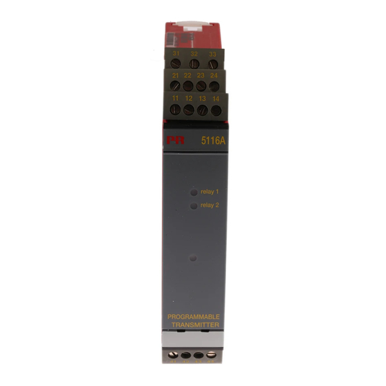
Page 14: Connections
Connections Supply: Inputs: RTD, 2-wire RTD, 3-wire RTD, 4-wire TC, internal CJC 41 42 41 42 41 42 Resistance, 2-wire Resistance, 3-wire Resistance, 4-wire TC, external CJC* 41 42 41 42 41 42 41 42 * If the device is reconfigured from temperature measurement with CJC connector to analogue measurement, the CJC connecter must be demounted. - Page 15 Connections Outputs: Current 2-wire installation Voltage 2 relays 11 12 11 12 11 12 21 22 5116V104-UK...
-
Page 16: Block Diagram
Block diagram Ex barrier, only 5116B Ex barrier, only 5116B 5116V104-UK... -
Page 17: Graphic Depiction Of Relay Actions Increasing / Decreasing
Graphic depiction of relay actions Increasing / Decreasing Relay units Relay units Hysteresis = 10 Setpoint = 50 Setpoint = 50 Hysteresis = 10 Off N.O. On N.O. Off N.O. Off N.O. On N.O. Off N.O. On N.C. On N.C. On N.C. -
Page 18: 5116 Connection To Loop Link
5116 connection to Loop Link Loop Link Commu- nication 5116 For connection of 5116B to Loop Link, please observe the instructions for instrinsically safe installation. Activation of the process calibration button Open the front cover and activate the switch with a pointed object, e.g. a small screwdriver. -
Page 19: Configuration Of Relay 1 & 2 In Preset
Configuration of relay 1 & 2 in PReset Parameter Value Description No relay function Setpoint Relay changes state at a limit on the span Relay changes state inside a range of the Type Setpoint window span Sensor error indication Only works for sensor error Power indication Relay is active when power is on % of input span... -
Page 20: Process Calibration 0% And 100% Or Only 0
Activate sw. 1. The LED will start flashing again. The input on 5116 has now been scaled according to the actual process values. When the option ”0% calibration” is actively configured in PReset it is possible to make the following process calibration. -
Page 21: Appendix
Appendix FM control drawing no. 5116QF01 5116V104-UK... -
Page 22: Fm Control Drawing No. 5116Qf01
Control Drawing 5116QF01 Hazardous (Classified) Location Unclassified Location Hazardous (Classified) Location Class I, Division 1, Group A,B,C,D Class I, Division 2, Group A,B,C,D Class II, Division 1 Group E, F, G Class I , Zone 2, Group IIC, IIB, IIA Class III, Division 1 Class I , Zone 0 and 1, Group IIC, IIB, IIA Class II, Zone 20 and 21... - Page 23 We are near you, all over the world Our trusted red boxes are supported wherever you are All our devices are backed by expert service and a 5-year business with a global reach. This means that we are warranty. With each product you purchase, you receive always nearby and know your local markets well.
- Page 24 Benefit today from PERFORMANCE MADE SMARTER PR electronics is the leading technology company specialized in making industrial process control safer, more reliable and more efficient. Since 1974, we have been dedicated to perfecting our core competence of innovating high precision technology with low power consumption.
Need help?
Do you have a question about the 5116 and is the answer not in the manual?
Questions and answers