
Related Manuals for PR electronics 5116


Summary of Contents for PR electronics 5116
- Page 1 5 1 1 6 P r o g r a m m a b l e T r a n s m i t t e r N o . 5 1 1 6 V 1 0 3 - U K F r o m s e r .
- Page 2 PR electronics A/S tilbyder et bredt program af analoge og digitale signalbehandlingsmoduler til industriel automation. Programmet består af Isolatorer, Displays, Ex-barrierer, Temperaturtransmittere, Universaltransmittere mfl. Vi har modulerne, du kan stole på i selv barske miljøer med elektrisk støj, vibrationer og temperaturudsving, og alle produkter opfylder de strengeste internationale standarder.
-
Page 3: Table Of Contents
Graphic depiction of relay actions Increasing / Decreasing .. 17 Graphic depiction of relay action Window ........17 5116 connection to Loop Link ............18 Activation of the process calibration button ....... 18 Configuration of relay 1 & 2 in PReset .......... 19 Process calibration 0% and 100% or only 0% ...... -
Page 4: Warning
VOLTAGE Troubleshooting the device. Repair of the device and replacement of circuit breakers must be done by PR electronics A/S only. WARNING To keep the safety distances, the relay contacts on the device must not be connected to both hazardous and non-hazardous volt ages at the same time. -
Page 5: Safety Instructions
SYMBOL IDENTIFICATION Triangle with an exclamation mark: Warning / demand. Potentially lethal situations. The CE mark proves the compliance of the device with the essential requirements of the directives. The double insulation symbol shows that the device is protected by double or reinforced insulation. -
Page 6: Instructions For Intrinsically Safe Installation Of 5116B
Should there be any doubt as to the correct handling of the device, please contact your local distributor or, alternatively, PR electronics A/S www.prelectronics.com Mounting and connection of the device should comply with national legislation for mounting of electric materials, i.e. -
Page 7: How To Demount System 5000
LIABILITY To the extent that the instructions in this manual are not strictly observed, the customer cannot advance a demand against PR electronics A/S that would otherwise exist according to the concluded sales agreement. HOW TO DEMOUNT SYSTEM 5000 First, remember to demount the connectors with hazardous voltages. -
Page 8: Application
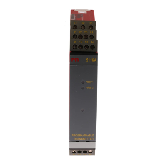
PROGRAMMABLE TRANSMITTER 5116 • Input for RTD, TC, mV, Ohm, potmeter, mA and V • 2-wire supply > 16.5 V • Bipolar voltage input • Output for current, voltage and 2 relays • Universal AC or DC supply Application • Linearised, electronic temperature measurement with RTD or TC sensor. -
Page 9: Applications
APPLICATIONS Input signals: RTD and lin. R polar Connection, wires Current Voltage V> 2.5 V 2-wire transmitter V<= 2.5 V Output signals: Relays 2-wire transmitter output Analogue, 0/4...20 mA and voltage Supply: 21.6...253 VAC 19.2...300 VDC 5 11 6 V 1 03 - UK... -
Page 10: Order: 5116
Order: 5116 Type Version 5116 Standard....: A ATEX Ex and FM..: B *NB! Please remember to order CJC connectors type 5910/5910Ex for TC... - Page 11 Response time (0...90%, 100...10%), programmable: Temperature / ± mV input ....... 400 ms to 60 s mA / V / mV input ..........250 ms to 60 s Signal dynamics, input ........... 22 bit Signal dynamics, output ........16 bit Accuracy, the greater of the general and basic values: General values Absolute...
- Page 12 Electrical specifications, temperature input, terminal 41, 42, 43 and 44 Max. offset ..............50% of selected max. value TC input: Min. Max. Min. Type temperature temperature span Standard +400°C +1820°C 200°C IEC584 -100°C +1000°C 50°C IEC584 -100°C +1200°C 50°C IEC584 -180°C +1372°C 50°C...
- Page 13 Electrical specifications, mA / V input, terminal 51, 52, 53 and 54 Max. offset ..............50% of selected max. value Current input: Measurement range ..........0...100 mA Min. measurement range (span) ......4 mA Input resistance: Supplied unit ............Nom. 10 Ω + PTC 10 Ω Non-supplied unit ..........
- Page 14 Relay outputs Max. voltage .............. 250 VRMS Max. current ............... 2 A / AC Max. AC power ............500 VA Max. current at 24 VDC ......... 1 A Sensor error detection ........... Break / Make / Hold / None Ex / I.S. approval - 5116B KEMA 04ATEX1316 X..........
- Page 15 Approvals EMC 2004/108/EC ..........EN 61326-1 LVD 2006/95/EC ............EN 61010-1 PELV/SELV ..............IEC 364-4-41 and EN 60742 UL, Standard for Safety ......... UL 61010-1 EAC TR-CU 020/2011..........EN 61326-1 Marine approval Det Norske Veritas, Ships & Offshore ..... Standard for Certification No. 2.4 I.S.
-
Page 16: Connections
CONNECTIONS Supply: Inputs: RTD, 2-wire RTD, 3-wire RTD, 4-wire TC, internal CJC 41 42 43 44 41 42 43 44 41 42 43 44 41 42 TC, external CJC* Resistance, 2-wire Resistance, 3-wire Resistance, 4-wire 41 42 43 44 41 42 43 44 41 42 43 44 41 42 43 44 * If the device is reconfigured from temperature measurement with CJC connector... -
Page 17: Connections
CONNECTIONS Outputs: Current 2-wire transmitter Voltage Relays 11 12 13 14 11 12 13 14 11 12 13 14 21 22 23 24 5 11 6 V 1 03 - UK... -
Page 18: Block Diagram
BLOCK DIAGRAM Ex barrier, only 5116B Ex barrier, only 5116B 5116V10 3 -UK... -
Page 19: Graphic Depiction Of Relay Actions Increasing / Decreasing
Graphic depiction of relay actions Increasing / Decreasing Relæenheder Relæenheder Hysterese = 10 Setpunkt = 50 Setpunkt = 50 Hysterese = 10 Off N.O. On N.O. Off N.O. Off N.O. On N.O. Off N.O. On N.C. On N.C. On N.C. On N.C. -
Page 20: 5116 Connection To Loop Link
5116 CONNECTION TO LOOP LINK Loop Link Commu- nication 5 1 1 6 For connection of 5116B to Loop Link, please observe the instructions for instrinsically safe installation. ACTIVATION OF THE PROCESS CALIBRATION BUTTON Open the front cover and activate the switch with a pointed object, e.g. -
Page 21: Configuration Of Relay 1 & 2 In Preset
Configuration of relay 1 & 2 in PReset Parameter Value Description No relay function Relay changes state at a limit Setpoint on the span Relay changes state inside a Type Setpoint window range of the span Sensor error indication Only works for sensor error Relay is active when power Power indication is on... -
Page 22: Process Calibration 0% And 100% Or Only 0
3. Apply the actual 100% value. 4. Activate sw. 1. The LED will start flashing again. The input on PRetrans 5116 has now been scaled according to the actual process values. When the option ”0% calibration” is actively configured in PReset it is possible to make the following process calibration. -
Page 23: Error Functions
ERROR FUNCTIONS Hardware error indication Value on ana- Relay contacts / Yellow Green LED logue output LEDs Error reason No power supply 0 mA / 0 V Contacts open / LEDs Off Constantly Off Blinking at Sensor error As configured As configured 1...2 Hz RAM checksum check failed *) -
Page 24: Appendix
APPENDIX FM CONTROL DRAWING NO. 5116QF01 5116V10 3 -UK... - Page 25 Control Drawing 5116QF01 Hazardous (Classified) Location Unclassified Location Hazardous (Classified) Location Class I, Division 1, Group A,B,C,D Class II, Division 1 Group E, F, G Class I, Division 2, Group A,B,C,D Class I , Zone 2, Group IIC, IIB, IIA Class III, Division 1 Class I , Zone 0 and 1, Group IIC, IIB, IIA Class II, Zone 20 and 21...
- Page 26 Displays Programmable displays with a wide selection of inputs and outputs for display of temperature, volume and weight, etc. Feature linearization, scaling, and difference measurement functions for programming via PReset software. Ex interfaces Interfaces for analog and digital signals as well as HART signals between sensors / I/P converters / frequency signals and control systems in Ex zone 0, 1 &...
- Page 27 www.prelectronics.com sales-uk@prelectronics.com www.prelectronics.com sales-us@prelectronics.com www.prelectronics.cn sales-cn@prelectronics.com www.prelectronics.be sales-be@prelectronics.com Head office Denmark www.prelectronics.com PR electronics A/S sales@prelectronics.dk Lerbakken 10 tel. +45 86 37 26 77 DK-8410 Rønde fax +45 86 37 30 85...
Need help?
Do you have a question about the 5116 and is the answer not in the manual?
Questions and answers