Advertisement
Available languages
Available languages
Quick Links
Isolation
Galvanic isolators for analogue and digital
signals as well as HART
®
signals. A wide product range
with both loop-powered and universal isolators featuring
linearisation, inversion, and scaling of output signals.
Displays
Programmable displays with a wide se-
lection of inputs and outputs for display of temperature,
volume, weight, etc. Feature linearisation, scaling, and
difference measurement functions for programming via
PReset software.
Ex barriers
Interfaces for analogue and digital signals
as well as HART
®
signals between sensors / I/P convert-
ers / frequency signals and control systems in Ex zone 0,
1 & 2. Feature options such as mathematical functions
and 2 wire transmitter interfaces.
Temperature
A wide selection of transmitters for DIN
form B mounting and DIN rail modules with analogue
and digital bus communication ranging from application-
specifi c to universal transmitters.
Backplane
Flexible motherboard solutions for sys-
tem 5000 modules. Our backplane range features fl exible
8 and 16 module solutions with confi guration via PReplan
8470 – a PC program with drop-down menus.
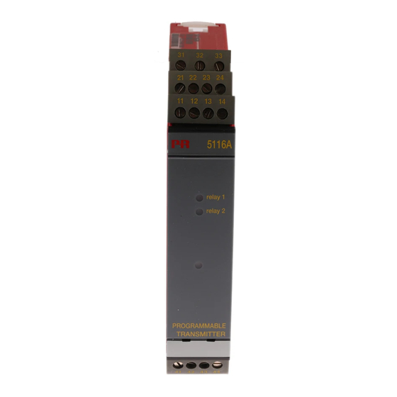
5 1 1 6
P r o g r a m m a b l e
T r a n s m i t t e r
N o . 5 1 1 6 V 1 0 1 - I N ( 0 5 2 3 )
F r o m s e r . n o . 0 4 0 6 7 7 0 0 1
S I G N A L S T H E B E S T
Side 1
DK
Page 21
UK
Page 41
FR
Seite 61
DE
Advertisement
Chapters

Related Manuals for PR electronics 5116


Summary of Contents for PR electronics 5116
- Page 1 Isolation Galvanic isolators for analogue and digital signals as well as HART ® signals. A wide product range with both loop-powered and universal isolators featuring linearisation, inversion, and scaling of output signals. Displays Programmable displays with a wide se- lection of inputs and outputs for display of temperature, volume, weight, etc.
-
Page 2: Table Of Contents
Blokdiagram ............... 17 Grafisk afbildning af relæaktionerne stigende /faldende ... 18 Grafisk afbildning af relæaktionen vindue ......18 Konfigurering af Relæ 1 & 2 i PReset ........ 19 5116 forbindelse til Loop Link (PC-konfigurering) ..... 20 Funktioner ved fejl .............. 20... -
Page 3: Sikkerhedsregler
Operatører er personer, som under normal drift med produktet skal indstille og Reparation af modulet og udskiftning af sikringer må kun betjene produktets trykknapper eller potentiometre, og som er gjort bekendt foretages af PR electronics A/S. med indholdet af denne manual. MODTAGELSE OG UDPAKNING: Udpak modulet uden at beskadige dette, og sørg for, at manualen altid følger... -
Page 4: Overensstemmelseserklæring
Hvis der er tvivl om modulets rette håndtering, skal der rettes henvendelse til PR electronics A/S den lokale forhandler eller alternativt direkte til: Lerbakken 10 PR electronics A/S, Lerbakken 10, 8410 Rønde, DK-8410 Rønde Danmark, tlf: +45 86 37 26 77. hermed at følgende produkt: Installation og tilslutning af modulet skal følge landets gældende regler for... -
Page 5: Afmontering Af System 5000
AFMONTERING AF SYSTEM 5000 PROGRAMMERBAR TRANSMITTER PRETRANS 5116 Husk først at demontere tilslutningsklemmerne med farlig spænding. • Indgang for RTD, TC, mV, Ohm, potmeter, mA og V Billede 1: • 2-trådsforsyning > 16,5 V Modulet frigøres fra DIN-skinnen ved at løfte i den nederste lås. -
Page 6: Bestillingsskema
Bestillingsskema: 5116 RTD og Lin. modstand Udgang Type Version 2 Relæer Forsyning 5116 Standard ATEX Ex-godkendt : B *NB! Husk at bestille CJC-stik type 5910 / 5910EEx i forbindelse med TC-indgange med intern CJC. Udgang Elektriske specifikationer: 2 Relæer Specifikationsområde: Forsyning -20°C til +60°C... - Page 7 Nøjagtighed, størst af generelle og basisværdier: Elektriske specifikationer, temperaturindgang, klemme 41, 42, 43 og 44: Generelle værdier Max. nulpunktsforskydning (offset) ..... 50% af valgt max. værdi Absolut Temperatur- TC-indgang: Indgangstype nøjagtighed koefficient Min. Max. Min. ≤ ±0,05% af span ≤ ±0,01% af span / °C Alle Type temperatur...
- Page 8 Elektriske specifikationer, mA- / V-indgang, Følerfejlsdetektering: klemme 51, 52, 53 og 54: Programmerbar ........... 0...23 mA Max. nulpunktsforskydning (offset) ..... 50% af valgt max. værdi NAMUR NE43 Upscale ....... 23 mA NAMUR NE43 Downscale ......3,5 mA Strømindgang: Relæudgange: Måleområde ..........0...100 mA Max.
-
Page 9: Anvisninger For Egensikker Installation Af 5116B
EEx- / I.S.-godkendelse: TILSLUTNINGER: KEMA 04ATEX1316X ........II (1) GD Forsyning: [EEx ia] IIC Anvendes for zone ........0, 1, 2, 20, 21 eller 22 Overholdte myndighedskrav: Standard: EMC 2004/108/EF, Emission og immunitet ....... EN 61326 LVD 73/23/EØF ..........EN 61010-1 Indgange: PELV/SELV ........... -
Page 10: Tilslutninger
BLOKDIAGRAM: TILSLUTNINGER: Udgange: Strøm 2-Trådsinstallation Spænding 2 Relæer 11 12 11 12 11 12 21 22... -
Page 11: Grafisk Afbildning Af Relæaktionen Vindue
Grafisk afbildning af relæaktionerne stigende / faldende: Konfigurering af Relæ 1 & 2 i PReset Parameternavn Værdi Beskrivelse Relæenheder Relæenheder Relæet har ingen funktion Relæet skifter tilstand ved en Setpunkt grænse på spannet Relæet skifter tilstand inden Type Setpunktsvindue for et område af spannet Hysterese = 10 Følerfejlsindikation Fungerer kun for følerfejl... - Page 12 Konstant Off Graphic depiction of relay action Window ......38 Configuration of relay 1 & 2 in PReset ....... 39 5116 connection to Loop Link (PC configuration) ..... 40 Falsk RAM kontrolsum* 0 mA / 0 V Kontakter åbne / LEDs Off Konstant On Error functions ..............
-
Page 13: Warnings
Repair of the module and replacement of circuit breakers RECEIPT AND UNPACKING: must be done by PR electronics A/S only. Unpack the module without damaging it and make sure that the manual always follows the module and is always available. The packing should always follow the module until this has been permanently mounted. -
Page 14: Declaration Of Conformity
Notified body for CENELEC/ATEX: UL International Demko A/S 0539 LIABILITY: To the extent that the instructions in this manual are not strictly observed, the custom er cannot advance a demand against PR electronics A/S that would otherwise exist according to the concluded sales agreement. Rønde, 6 June 2005 Peter Rasmussen Manufacturer’s signature... -
Page 15: How To Dismantle System 5000
Technical characteristics: • Within a few seconds the user can program PR5116 to suit the specific appli- cation. As the 5116 is designed with electronic hardware switches, it is not necessary to open the module for setting of DIP switches. -
Page 16: Order
Order: 5116 RTD and lin. resistance Output Type Version 2 relays Supply 5116 Standard ATEX Ex approved *NB! Please remember to order CJC connectors type 5910 / 5910EEx for TC inputs with internal CJC. Output Electrical specifications: 2 relays Specifications range: Supply -20°C to +60°C... - Page 17 Accuracy, the greater of the general and basic values: Electrical specifications, temperature input, terminal 41, 42, 43 and 44: General values Max. offset ..........50% of selected max. value Absolute Temperature TC input: Input type accuracy coefficient Min. Max. Min. ≤...
- Page 18 Electrical specifications, mA / V input, Sensor error detection: terminal 51, 52, 53 and 54: Programmable ..........0...23 mA Max. offset ..........50% of selected max. value NAMUR NE43 Upscale ....... 23 mA NAMUR NE43 Downscale ......3.5 mA Current input: Measurement range ........
-
Page 19: Instructions For Intrinsically Safe Installation Of 5116B
EEx / I.S. approval: CONNECTIONS: KEMA 04ATEX1316X ........II (1) GD Supply: [EEx ia] IIC Applicable for zone ........0, 1, 2, 20, 21 or 22 Observed authority requirements: Standard: EMC 2004/108/EC, Emission and immunity ....... EN 61326 LVD 73/23/EEC ..........EN 61010-1 Inputs: PELV/SELV ........... -
Page 20: Connections
BLOCK DIAGRAM: CONNECTIONS: Outputs: Current 2-wire installation Voltage 2 relays 11 12 11 12 11 12 21 22... -
Page 21: Graphic Depiction Of Relay Actions Increasing / Decreasing
Graphic depiction of relay actions Increasing / Decreasing: Configuration of relay 1 & 2 in PReset Relay units Relay units Parameter Value Description No relay function Relay changes state at a limit Setpoint on the span Relay changes state inside a Type Setpoint window range of the span... -
Page 22: Error Functions
Contacts open / LEDs Off Constantly On Illustration graphique de l’action de relais fenêtre ..... 58 Fonctions d’erreur .............. 59 Connexion entre le 5116 et le kit de programmation EEPROM checksum check failed 0 mA / 0 V Contacts open / LEDs Off Constantly On (configuration par PC) ............ -
Page 23: Avertissements
RECEPTION ET DEBALLAGE Déballez le module sans l’endommager. Le guide doit toujours être disponible Seule PR electronics SARL est autorisée à réparer le module et se trouver à proximité du module. De même, il est recommandé de conserver et à remplacer les dis joncteurs. -
Page 24: Déclaration De Conformité
SARL, Zac du Chêne, Activillage, 2, allée des Sorbiers, F-69500 Bron déclare que le produit suivant : (tél. : (0) 472 140 607) ou à PR electronics A/S, Lerbakken 10, DK-8410 Rønde, Danemark (tél. : +45 86 37 26 77). -
Page 25: Démontage Du Systeme 5000
DEMONTAGE DU SYSTEME 5000 TRANSMETTEUR PROGRAMMABLE PRETRANS 5116 Tout d’abord, n’oubliez pas de démonter les connecteurs où règnent des ten sions dangereuses. • Entrées : RTD, TC, mV, Ohm, potentiomètre, mA et V Figure 1 : • Alimentation 2-fils > 16,5 V Débloquez le verrou inférieur pour... -
Page 26: Spécifications Électriques
Référence : 5116 RTD et résistance lin. Sortie Type Version 2 relais Alimentation Standard 5116 Homologué ATEX Ex : B *NB ! Pour des entrées TC à CSF interne, rappelez-vous de commander le bornier réf. 5910 / 5910EEx. Sortie Spécifications électriques : 2 relais Plage des spécifications :... - Page 27 Précision, la plus grande des valeurs générales et de base : Spécifications électriques, entrée température, borne 41, 42, 43 et 44 : Valeurs générales Décalage max..........50% de la valeur max. sélectionnée Type Précision Coefficient d’entrée absolue de température Entrée TC : Température Température...
- Page 28 Spécifications électriques, entrées mA / V, Détection de rupture capteur : borne 51, 52, 53 et 54 : Programmable ..........0...23 mA Décalage max..........50% de la valeur max. sélectionnée NAMUR NE43 Haute ........23 mA NAMUR NE43 Basse ........3,5 mA Entrée courant : Sorties relais : Gamme de mesure ........
-
Page 29: Instructions Pour Installation De Sécurité Intrinsèque Du 5116B
Approbation EEx / S.I. : CONNEXIONS : KEMA 04ATEX1316X ........II (1) GD Alimentation : [EEx ia] IIC Applicable pour zone ........0, 1, 2, 20, 21 ou 22 Agréments et homologations : Standard : CEM 2004/108/CE, Emission et immunité ....EN 61326 DBT 73/23/CEE ........... -
Page 30: Connexions
SCHEMA DE PRINCIPE : CONNEXIONS : Sorties : Courant Installation 2-fils Tension 2 relais 21 22 11 12 11 12 11 12... -
Page 31: Illustration Graphique Des Actions De Relais Montante / Descendante
Illustration graphique des actions de relais montante / Configuration des relais 1 & 2 à l’aide de PReset descendante : Paramètre Valeur Description Unités de relais Unités de relais Pas de fonction du relais Le relais change d’état à la Consigne limite de l’échelle Le relais change d’état sur la... -
Page 32: Fonctions D'erreur
0 mA / 0 V Fehlfunktionen ..............79 Contacts ouverts / LEDs Constamment 5116 Verbindung mit Loop Link (PC-Konfiguration) ..80 Erreur de la mémoire EEPROM 0 mA / 0 V Konfiguration der Relais ............. 80 Contacts ouverts / LEDs Constamment Programme principal arrêté... -
Page 33: Sicherheitsregeln
Handbuch stets in der Nähe des Moduls und zugänglich ist. Die Verpackung Reparaturen des Moduls und Austausch von Sicherungen sollte beim Modul bleiben, bis dieses am endgültigen Platz mon tiert ist. dürfen nur von PR electronics A/S vorgenommen werden. Kontrollieren Sie beim Empfang, ob der Modultyp Ihrer Bestellung entsprich t. UMGEBUNGSBEDINGUNGEN:... -
Page 34: Konformitätserklärung
Händler vor Ort Kontakt aufnehmen. Sie können aber auch direkt mit PR electronics GmbH, Bamlerstraße 92, D-45141 Essen, (Tel.: (0) Als Hersteller bescheinigt 201 860 6660) oder mit PR electronics A/S, Lerbakken 10, DK-8410 Rønde, PR electronics A/S Dänemark (Tel.: +45 86 37 26 77) Kontakt aufnehmen. -
Page 35: Zerlegung Des Systems 5000
Technische Merkmale: • PR5116 kann vom Benutzer innerhalb von wenigen Sekunden für die gewünschte Applikation programmiert werden. Das 5116 ist mit elektroni- schen Hardware-Schaltern ausgestattet und es ist nicht notwendig das Gerät zur Einstellung von DIP-Schaltern zu öffnen. -
Page 36: Elektrische Daten
Bestellangaben: 5116 WTH und lin. Widerstand Ausgang Version 2 Relais Versorgung 5116 Standard ATEX Ex-Zulassung : B *Zu beachten! In Verbindung mit TE-Eingänge mit interner Vergleichsstellenkompensation (CJC) sind die CJC-Anschlussstecker Ausgang Typ 5910 / 5910EEx zu bestellen. 2 Relais Elektrische Daten:... - Page 37 Genauigkeit: Der höhere Wert der allgemeinen Werte oder Grundwerte: Elektrische Daten, Temperatureingang, Klemme 41, 42, 43 und 44: Allgemeine Werte Max. Nullpunktverschiebung (offset) ... 50% d. gew. Maximalwertes Eingangs- Absolute Temperatur- Genauigkeit koeffizient TE-Eingang: Min. Max. Min. ≤ ±0,05% d. Messsp. ≤...
- Page 38 Elektrische Daten, mA- / V-Eingang, Klemme 51, 52, 53 und 54: Fühlerfehlererkennung: Max. Nullpunktverschiebung (offset) ... 50% d. gew. Maximalwertes Programmierbar .......... 0...23 mA NAMUR NE43 Upscale ....... 23 mA NAMUR NE43 Downscale ......3,5 mA Stromeingang: Messbereich ..........0...100 mA Relaisausgänge: Min.
-
Page 39: Richtlinien Zur Installation Des 5116B Mit Ex-Anwendung
EEx- / I.S.-Zulassung: ANSCHLÜSSE: KEMA 04ATEX1316X ........II (1) GD Versorgung: [EEx ia] IIC Geeignet für Zone ........0, 1, 2, 20, 21 oder 22 Eingehaltene Behördenvorschriften: Norm: EMV 2004/108/EG, Abstrahlung und Störfestigkeit ..EN 61326 LVD 73/23/EWG .......... EN 61010-1 Eingänge: PELV/SELV ........... -
Page 40: Anschlüsse
BLOCKDIAGRAMM: ANSCHLÜSSE: Ausgänge: Strom 2-Draht-Installation Spannung 2 Relais 11 12 11 12 11 12 21 22... -
Page 41: Graphische Abbildung Der Relaisfunktionen Steigend / Fallend
Konfiguration der Relais 1 & 2 mit PReset Graphische Abbildung der Relaisfunktionen Steigend / Fallend: Parameter Wert Beschreibung Relaiseinheiten Relaiseinheiten Keine Relaisfunktion Relais wechselt Status bei einem Wert Sollwert der Spanne Relais wechselt Status innerhalb eines Sollwert Fenster Bereichs der Spanne Hysterese = 10 Sensorfehler Anzeige Schaltet nur bei Sensorfehler... -
Page 42: Fehlfunktionen
5116 VERBINDUNG MIT LOOP LINK Loop Link Kommu- nikation 5116 5116 Bei der Verbindung von Loop Link mit dem 5116B beachten Sie bitte die Sicherheits-Richtlinien. FEHLFUNKTIONEN Hardware Fehleranzeige Wert auf analo- Relaiskontakte / Gelbe Grüne LED Fehlergrund gen Ausgang LEDs... - Page 43 Subsidiaries PR electronics A/S tilbyder et bredt program af analoge og di- France gitale signalbehandlingsmoduler til industriel automation. Vores PR electronics Sarl Zac du Chêne, Activillage sales@prelectronics.fr kompetenceområder omfatter: Isolation, Displays, Ex-barrierer, 2, allée des Sorbiers tel. +33 (0) 4 72 14 06 07 Temperatur samt Backplanes.
Need help?
Do you have a question about the 5116 and is the answer not in the manual?
Questions and answers