
Related Manuals for PR 5114


Summary of Contents for PR 5114
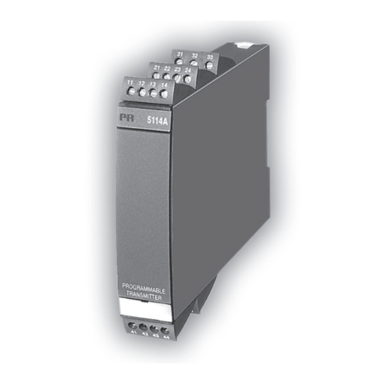
- Page 1 5 1 1 4 P r o g r a m m a b l e T r a n s m i t t e r N o . 5 1 1 4 V 1 0 7 - U K F r o m s e r .
- Page 2 Vores motto »Signals the Best« er indbegrebet af denne filosofi – og din garanti for kvalitet. PR electronics A/S offers a wide range of analog and digital signal conditioning devices for industrial automation. The product range includes Isolators, Displays, Ex Interfaces, Temperature Transmitters, and Multifunctional Devices.
-
Page 3: Table Of Contents
Technical characteristics ..............Input types ....................Output ......................Configuration .................... Electrical specifications................ Order ......................13 5114 connection to Loop Link ............13 Block diagram ................... 14 Selection of input type: (5114A) ............. 15 5 11 4 V 1 07 - UK... -
Page 4: Warning
General mounting, connection and disconnection of wires. Troubleshooting the device. Repair of the device and replacement of circuit breakers must be done by PR electronics A/S only. WARNING SYSTEM 5000 must be mounted on DIN rail according to DIN 46277. -
Page 5: Symbol Identification
SYMBOL IDENTIFICATION Triangle with an exclamation mark: Warning / demand. Potentially lethal situations. The CE mark proves the compliance of the device with the essential requirements of the directives. The double insulation symbol shows that the device is protected by double or reinforced insulation. - Page 6 When disconnected, the device may be cleaned with a cloth moistened with distilled water. LIABILITY: To the extent the instructions in this manual are not strictly observed, the custom er cannot advance a demand against PR electronics A/S that would otherwise exist according to the concluded sales agreement. 5114V10 7 -UK...
-
Page 7: How To Demount System 5000
HOW TO DEMOUNT SYSTEM 5000 First, remember to demount the connectors with hazardous voltages. By lifting the bottom lock, the device is detached from the DIN rail as shown in picture 1. Then, by lifting the upper lock and pulling the front plate simultaneously the PCB is removed as shown in picture 2. -
Page 8: Application
Measurement range, signal parameters, and output span are configured to the present task by way of a PC and PR electronics A/S’ communica tions interface Loop Link. INPUT TYPES Temperature input - jumpers in position 1:... -
Page 9: Output
Loop 4...20 mA current output: By wiring the current signal alternatively, the output works as a loop output. If the supply voltage for the 5114 disappears, the output current drops to < 4 mA. Sensor error detection: The output can be set up at an RTD, thermocouple and linear resistance input to go to max., to min. -
Page 10: Configuration
CONFIGURATION The transmitter is configured to the present task by way of a PC and PR electronics A/S’ communications interface Loop Link. The communications interface is galvanically isolated to protect the PC port. Communication is 2-way to allow the retrieval of the transmitter set-up into the PC and to allow the transmission of the PC set-up to the transmitter. - Page 11 Accuracy, the greater of the general and basic values: General values Absolute Temperature Input type accuracy coefficient ±0.05% of span ±0.01% of span / °C ≤ ≤ Basic values Basic Temperature Input type accuracy coefficient ±4 µA ±0.4 µA / °C ≤...
- Page 12 Electrical specifications, temperature input: TC input: Min. Max. Min. Type temperature temperature span Standard +400°C +1820°C 200°C IEC584 -100°C +1000°C 50°C IEC584 -100°C +1200°C 50°C IEC584 -180°C +1372°C 50°C IEC584 -100°C +900°C 50°C DIN 43710 -180°C +1300°C 100°C IEC584 -50°C +1760°C 200°C IEC584...
-
Page 13: Current Output
Electrical specifications, mA / V / mV input: Current input: Measurement range ..........0...100 mA Min. measurement range (span) ......4 mA Max. offset ..............50% of selec. max. value Input resistance: Supplied unit ............Nom. 10 Ω + PTC 10 Ω Non-supplied unit .......... - Page 14 Ex / I.S. data for 5114B, all types: Terminal 31, 32, and 33 .................. : 250 V Ex / I.S. data for 5114 B1 (channel 1 for 5114B3): Terminal 41, 42, 44 to 43 (51, 52, 54 to 53) ................... : 7.5 VDC ..................
-
Page 15: Order
Note! For TC inputs with internal CJC, remember to order the CJC connectors type 5910 / 5910 Ex (ch. 1) and 5913 / 5913 Ex (ch. 2). 5114 CONNECTION TO LOOP LINK 5 11 4 V 1 07 - UK... -
Page 16: Block Diagram
BLOCK DIAGRAM 5114V10 7 -UK... -
Page 17: Selection Of Input Type: (5114A)
SELECTION OF INPUT TYPE: (5114A) Input JP 1 JP 2 JP 3 JP 4 Temperature channel 1 Temperature channel 2 Current / voltage channel 1 Current / voltage channel 2 5 11 4 V 1 07 - UK... - Page 18 Displays Programmable displays with wide selection of inputs and outputs for display of temperature, volume and weight, etc. Feature linearization, scaling, and difference measurement functions for programming via PReset software. Ex interfaces Interfaces for analogue and digital signals as well as HART signals between sensors / I/P converters / frequency signals and control systems in Ex zone 0, 1 &...
- Page 19 www.prelectronics.com sales-uk@prelectronics.com www.prelectronics.com sales-us@prelectronics.com www.prelectronics.cn sales-cn@prelectronics.com www.prelectronics.be sales-be@prelectronics.com Head office Denmark www.prelectronics.com PR electronics A/S sales@prelectronics.dk Lerbakken 10 tel. +45 86 37 26 77 DK-8410 Rønde fax +45 86 37 30 85...
Need help?
Do you have a question about the 5114 and is the answer not in the manual?
Questions and answers