
Related Manuals for PR electronics 5131


Summary of Contents for PR electronics 5131
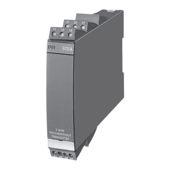
- Page 1 5 1 3 1 P r o g r a m m a b l e T r a n s m i t t e r N o . 5 1 3 1 V 1 0 4 - U K S e r .
- Page 2 PR electronics A/S tilbyder et bredt program af analoge og digitale signalbehandlingsmoduler til industriel automation. Programmet består af Isolatorer, Displays, Ex-barrierer, Temperaturtransmittere, Universaltransmittere mfl. Vi har modulerne, du kan stole på i selv barske miljøer med elektrisk støj, vibrationer og temperaturudsving, og alle produkter opfylder de strengeste internationale standarder.
-
Page 3: Table Of Contents
Input types ....................Output ......................Sensor error detection ................Configuration .................... Electrical specifications................ Order ......................12 5131 connection to Loop Link ............13 Selection of input type: (5131A) ............. 13 Blockdiagram .................... 14 5 13 1 V 1 04 - UK... -
Page 4: Warning
General mounting, connection and disconnection of wires. Troubleshooting the device. Repair of the device and replacement of circuit breakers must be done by PR electronics A/S only. WARNING SYSTEM 5000 must be mounted on DIN rail according to DIN 46277. -
Page 5: Symbol Identification
SyMBOL IDENTIFICATION Triangle with an exclamation mark: Warning / demand. Potentially lethal situations. The CE mark proves the compliance of the device with the essential requirements of the directives. The double insulation symbol shows that the device is protected by double or reinforced insulation. - Page 6 When disconnected, the device may be cleaned with a cloth moistened with distilled water. LIABILITy To the extent the instructions in this manual are not strictly observed, the customer cannot advance a demand against PR electronics A/S that would otherwise exist according to the concluded sales agreement. 5131V10 4 -UK...
-
Page 7: How To Demont System 5000
HOW TO DEMONT SySTEM 5000 First, remember to demount the connectors with hazardous voltages. By lifting the bottom lock, the device is detached from the DIN rail as shown in picture 1. Then, by lifting the upper lock and pulling the front plate simultaneously the PCB is removed as shown in picture 2. -
Page 8: Application
Measurement range, signal parameters, and output span are configured to the present task by way of a PC and PR electronics A/S’ communications interface Loop Link. Input types Temperature input - jumper in position 1:... -
Page 9: Output
Configuration The transmitter is configured to the present task by way of a and PR electronics A/S’ communications interface Loop Link. The transmitter can be configured with or without a connected supply voltage as the communications interface supplies the necessary voltage to the set-up. -
Page 10: Electrical Specifications
Electrical specifications Specifications range: -20°C to +60°C Common specifications: Supply voltage ............7.5...35 VDC Fuse ................50 mA SB / 250 VAC Consumption during programming ....3...8 mA Isolation voltage, test / operation ....3.75 kVAC / 250 VAC Communications interface ........Loop Link Signal / noise ratio .......... - Page 11 Basic values Basic Temperature Input type accuracy coefficient ±4 µA ±0.4 µA / °C ≤ ≤ Volt ±10 µV ±1 µV / °C ≤ ≤ ±0.2°C ±0.01°C / °C ≤ ≤ Lin. resistance ±0.1 ±10 m / °C ≤ Ω ≤...
- Page 12 Electrical specifications, temperature input: TC input: Min. Max. Min. Type temperature temperature span Standard +400°C +1820°C 200°C IEC584 -100°C +1000°C 50°C IEC584 -100°C +1200°C 50°C IEC584 -180°C +1372°C 50°C IEC584 -100°C +900°C 50°C DIN 43710 -180°C +1300°C 100°C IEC584 -50°C +1760°C 200°C IEC584...
- Page 13 Electrical specifications, mA / V / mV input: Current input: Measurement range ..........0...100 mA Min. measurement range (span) ......4 mA Max. offset ..............50% of selec. max. value Input resistance: Supplied unit.............. Nom. 10 Ω + PTC 10 Ω Non-supplied unit ............
-
Page 14: Order
EN 50281-1-1 Of span = Of the presently selected range Order Type Version Input Channels 5131 Standard RTD / TC / R / mA / V / mV Single Double ATEX Ex RTD / TC / mV / R mA / V / mV... -
Page 15: 5131 Connection To Loop Link
5131 CONNECTION TO LOOP LINK Receiving Loop communication Disconnect when "on line" equipment loop communication is used Black Red supp Yellow Input 4...20 mA Front communication can be used with or without 5131 connected Green to the receiving equipment CH 2... -
Page 16: Blockdiagram
BLOCKDIAGRAM 5131V10 4 -UK... - Page 17 Displays Programmable displays with a wide selection of inputs and outputs for display of temperature, volume and weight, etc. Feature linearization, scaling, and difference measurement functions for programming via PReset software. Ex interfaces Interfaces for analog and digital signals as well as HART signals between sensors / I/P converters / frequency ®...
- Page 18 www.prelectronics.se sales-se@prelectronics.com www.prelectronics.co.uk sales-uk@prelectronics.com www.prelectronics.com sales-us@prelectronics.com www.prelectronics.cn sales-cn@prelectronics.com Head office Denmark www.prelectronics.com PR electronics A/S sales-dk@prelectronics.com Lerbakken 10 tel. +45 86 37 26 77 DK-8410 Rønde fax +45 86 37 30 85...
Need help?
Do you have a question about the 5131 and is the answer not in the manual?
Questions and answers