Table of Contents
Advertisement
Quick Links
Advertisement
Table of Contents

Related Manuals for Advantech PCI-1737U


Summary of Contents for Advantech PCI-1737U
- Page 1 PCI-1737U/1739U 24/48 Channel Digital I/O Output Card User Manual...
- Page 2 No part of this man- ual may be reproduced, copied, translated or transmitted in any form or by any means without the prior written permission of Advantech Co., Ltd. Information provided in this manual is intended to be accurate and reli- able.
- Page 3 Product Warranty (2 years) Advantech warrants to you, the original purchaser, that each of its prod- ucts will be free from defects in materials and workmanship for two years from the date of purchase. This warranty does not apply to any products which have been repaired or...
-
Page 4: Declaration Of Conformity
This product has passed the CE test for environmental specifications when shielded cables are used for external wiring. We recommend the use of shielded cables. This kind of cable is available from Advantech. Please contact your local supplier for ordering information. - Page 5 National Fire Protection Association, work sites are classified into different classes, divisions and groups, based on hazard considerations. PCI-1737U/PCI-1739U is compliant with the specifications of Class I, Division 2, Groups A, B, C and D indoor hazards. Technical Support and Assistance Step 1.
- Page 6 Before setting up the system, check that the items listed below are included and in good condition. If any item does not accord with the table, please contact your dealer immediately. • PCI-1737U/PCI-1739U card • Companion CD-ROM (Device Drivers included) • This User Manual Safety Instructions Read these safety instructions carefully.
- Page 7 The sound pressure level at the operator's position according to IEC 704- 1:1982 is no more than 70 dB (A). DISCLAIMER: This set of instructions is given according to IEC 704-1. Advantech disclaims all responsibility for the accuracy of any statements contained herein. Safety Precaution - Static Electricity Follow these simple precautions to protect yourself from harm and the products from damage.
- Page 8 PCI-1737U/PCI-1739U User Manual viii...
-
Page 9: Table Of Contents
Pin Assignment For PCI-1737U ........21 Figure 3.3:Connector 1 ..........22 Figure 3.4:Connector 2 & 3 (Optional) ....... 23 3.2.2 I/O Connector Signal Description For PCI-1737U ..23 Table 3.4:I/O Connection signal Description ....23 3.2.3 Pin Assignment For PCI-1739U ........24 Figure 3.5:PCI-1739U Pin Assignments ..... - Page 10 Interrupt Flag Bit ............30 Table 4.5: Interrupt flag bit values ....... 30 Appendix A Specifications ..........32 PCI-1737U ..............32 PCI-1739U ..............33 Appendix B Function Block..........36 Figure B.1:PCI-1737U ..........36 Figure B.2:PCI-1739U ..........36 MIC-3780 User Manual...
- Page 11 General Information Sections include: • Features • Applications • Installation Guide • Software Overview • Device Driver Programming Roadmap • Accessories...
-
Page 12: Chapter 1 General Information
Chapter 1 General Information The PCI-1737U/PCI-1739U is a 24/48-bit DI/O card with PCI bus. It pro- vides you with 24/48 bits of parallel digital input/output. It emulates mode 0 of the 8255 PPI chip, but the buffered circuits offer a higher driv- ing capability than the 8255. -
Page 13: Applications
• Parallel data transfer • Sensing the signals of TTL, DTL, CMOS logic • Driving indicator LED's 1.3 Installation Guide Before you install your PCI-1737U/PCI-1739U card, please make sure you have the following necessary components: • PCI-1737U/PCI-1739U DA&C card • PCI-1737U/PCI-1739U User Manual •... -
Page 14: Figure 1.1:Installation Flow Chart
Figure 1.1: Installation Flow Chart PCI-1737U/PCI-1739U User Manual 4... -
Page 15: Software Overview
1.4 Software Overview Advantech offers a rich set of DLL drivers, third-party driver support and application software to help fully exploit the functions of your PCI- 1737U/PCI-1739U card: • Device Drivers (on the companion CD-ROM) • LabVIEW driver • Advantech ActiveDAQ •... -
Page 16: Device Driver Programming Roadmap
• C++ Builder For instructions on how to begin programming in each development tool, Advantech offers a Tutorial Chapter in the Device Drivers Manual for your reference. Please refer to the corresponding sections in this chapter on the Device Drivers Manual to begin your programming efforts. You can also look at the example source code provided for each programming tool, since they can get you very well oriented. -
Page 17: Programming With Device Drivers Function Library
1.5.2 Programming with Device Drivers Function Library Advantech Device Drivers offer a rich function library that can be utilized in various application programs. This function library consists of numer- ous APIs that support many development tools, such as Visual C++, Visual Basic, Delphi and C++ Builder. - Page 18 ADAM-3950 50-pin Flat Cable Wiring Terminal for DIN-rail Mounting The ADAM-3900 series consists of universal screw terminal modules designed for field signal wiring in industrial applications. They can be connected to the analog and digital ports of Advantech products such as the PCL series. PCI-1737U/PCI-1739U...
- Page 19 Installation .Sections include: • Unpacking • Driver Installation • Hardware Installation • Device Configuration...
-
Page 20: Chapter 2 Installation
Chapter 2 Installation 2.1 Unpacking After receiving your PCI-1737U/PCI-1739U package, please inspect its contents first. The package should contain the following items: • PCI-1737U/PCI-1739U card • Companion CD-ROM (Device Drivers included) • User Manual The PCI-1737U/PCI-1739U cards harbor certain electronic components vulnerable to electrostatic discharge (ESD). -
Page 21: Driver Installation
PC or transport it else- where. 2.2 Driver Installation We recommend you install the driver before you install the PCI-1737U/ PCI-1739U card into your system, since this will guarantee a smooth installation process. The Advantech Device Drivers Setup program for the PCI-1737U/PCI- 1739U card is included in the companion CD-ROM that is shipped with your DA&C card package. -
Page 22: Figure 2.1: Advantech Automation Software Setup
Figure 2.1: Advantech Automation Software Setup 3. Select the Device Drivers option. 4. Select the specific device then just follow the installation instructions step by step to complete your device driver installation and setup. Figure 2.2: Different Options for Driver Setup... -
Page 23: Hardware Installation
4. Touch the metal part on the surface of your computer to neutralize the static electricity that might be on your body. 5. Insert the PCI-1737U/PCI-1739U card into a PCI slot. Hold the card only by its edges and carefully align it with the slot. Insert the card firmly into place. -
Page 24: Device Configuration
2.4 Device Configuration The Advantech Device Manager Program is a utility that allows you to set up, configure and test your device, and later stores your settings on the system registry. These settings will be used when you call the APIs of Advantech Device Drivers. -
Page 25: Figure 2.4:The Device Setting Dialog Box
Figure 2.4: The Device Setting Dialog Box After your card is properly installed and configured, you can click the ‘Test’ button to test your hardware by using the testing utility supplied. Figure 2.5: Digital Input Test Utility For more detailed information, please refer to Chapter 2 of the Device Drivers Manual. - Page 26 PCI-1737U/PCI-1739U User Manual 16...
- Page 27 Signal Connections .Sections include: • Switch and Jumper Settings • Signal Connections...
-
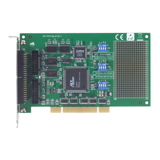
Page 28: Figure 3.1:Pci-1737U Board Layout
PCI- 1737U/PCI-1739U via the I/O connector. Figure 3.1: PCI-1737U Board Layout CN1: IDC 50-pin header for digital input/output port A, B, and C CN2: IDC 20-pin header digital input/output port A and B (optional) -
Page 29: Figure 3.2:Pci-1739U Board Layout
SW5: BoardID switch (0~15) 3.1 Switch and Jumper Settings We designed the PCI-1737U/PCI-1739U with ease-of-use in mind. It is a "plug and play" card, i.e. the system BIOS assigns the system resources such as base address and interrupt automatically. There are only some functions with 3 switches (5 for PCI-1739U) to be set by the user. -
Page 30: Port Status Setting
3.1.1 Port Status Setting (SW1 for PCI-1737U, SW1/SW2 for PCI-1739U) Users can set the onboard I/O ports as input or output separately. Please be aware that once dials the switch to “ON” (Set port as output); the software setting will be ignored. -
Page 31: Boardid Setting
3.2 Signal Connections 3.2.1 Pin Assignment For PCI-1737U PCI-1737U is quipped with a standard IDC 50-pin header. However you can also access the signals on CN1 by attaching IDC 20-pin connectors to the holes in the PCB at CN2 and CN3 by yourself. The pin assignments are as follows. -
Page 32: Figure 3.3:Connector 1
Figure 3.3: Connector 1 PCI-1737U/PCI-1739U User Manual 22... -
Page 33: Figure 3.4:Connector 2 & 3 (Optional)
Figure 3.4: Connector 2 & 3 (Optional) 3.2.2 I/O Connector Signal Description For PCI-1737U Table 3.4: I/O Connection signal Description Signal Ref. Direction Description PA <0~7> Input/Out- Digital input/ output port A, chan- nel 0~7. PB <0~7> Input/Out- Digital input/ output port B, chan- nel 0~7. -
Page 34: Pin Assignment For Pci-1739U
3.2.3 Pin Assignment For PCI-1739U PCI-1739U is equipped with 2 standard IDC 50-pin headers. The pin assignments are as follows. Figure 3.5: PCI-1739U Pin Assignments 3.2.4 I/O Connector Signal Description For PCI-1737U Table 3.5: I/O Connection signal Description Signal Ref. - Page 35 Operation Sections include: • Configuration • 8255 Mode 0 Function Definitions • Interrupt Handling...
-
Page 36: Chapter 4 Operation
Chapter 4 Operation This chapter describes the operating characteristics of the PCI-1737U/ PCI-1739U. The DLL driver allows a user to access all of the card's func- tions without register level programming. Please see the User's Manual for the driver bundled with this card for more information. For users who... -
Page 37: Interrupt Function Of The Dio Signals
4.2.1 Interrupt Function of the DIO Signals The I/O pin (PC00) can be used to generate hardware interrupt. A user can program the interrupt control register (Base + 8) to select the interrupt sources. Refer to "Interrupt Function" in this chapter for details about interrupt control. -
Page 38: Initial Configuration
4.3 Interrupt Handling Two lines in the I/O port (C0 and C4) are connected to the interrupt cir- cuitry. The "Interrupt Control Register" of the PCI-1737U/PCI-1739U controls how the combination of the two signals generates an interrupt. When the interrupt request signal is generated, the software can service the request signal by ISR. -
Page 39: Interrupt Source Control
M00 and M01: mode bits of port0 E0: triggering edge control bits F0: interrupt flag bit 4.3.3 Interrupt Source Control The "mode bits" in the interrupt control register determine the allowable sources of signals generating an interrupt. Bit 0 and bit 1 determine the interrupt source for port. -
Page 40: Interrupt Flag Bit
"1" to this bit to clear the interrupt. This bit must be cleared in the ISR to service the next incoming interrupt. Table 4.5: Interrupt flag bit values Interrupt status Read Interrupt exists No interrupt Write Clear interrupt Don’t care PCI-1737U/PCI-1739U User Manual 30... - Page 41 Specifications...
-
Page 42: A.1 Pci-1737U
Appendix A Specifications A.1 PCI-1737U Bus interface PCI bus spec. 2.2 compliant and support both 3.3V and 5V signaling (PCI universal card) Digital Input/Output I/O lines: 24 Programming mode: 8255 PPI mode 0 Digital Output Logic level 0: 0.4Vmax.@24mA(sink) Logic level 1: 2.4 V min.@15mA(source) Digital Input Logic level 0: 0.4Vmax. -
Page 43: Pci-1739U
A.2 PCI-1739U Bus interface PCI bus spec. 2.2 compliant and support both 3.3V and 5V signaling (PCI universal card) Digital Input/Output I/O lines: 48 Programming mode: 8255 PPI mode 0 Digital Output Logic level 0: 0.4Vmax.@24mA(sink) Logic level 1: 2.4 V min.@15mA(source) Digital Input Logic level 0: 0.4Vmax. - Page 44 PCI-1737U/PCI-1739U User Manual 34...
- Page 45 Function Block...
-
Page 46: Figure B.1:Pci-1737U
Appendix B Function Block Figure B.1: PCI-1737U Figure B.2: PCI-1739U PCI-1737U/PCI-1739U User Manual 36...
Need help?
Do you have a question about the PCI-1737U and is the answer not in the manual?
Questions and answers