Table of Contents
Advertisement
Quick Links
Download this manual
See also:
User Manual
Advertisement
Table of Contents

Related Manuals for DFI KU968


Summary of Contents for DFI KU968
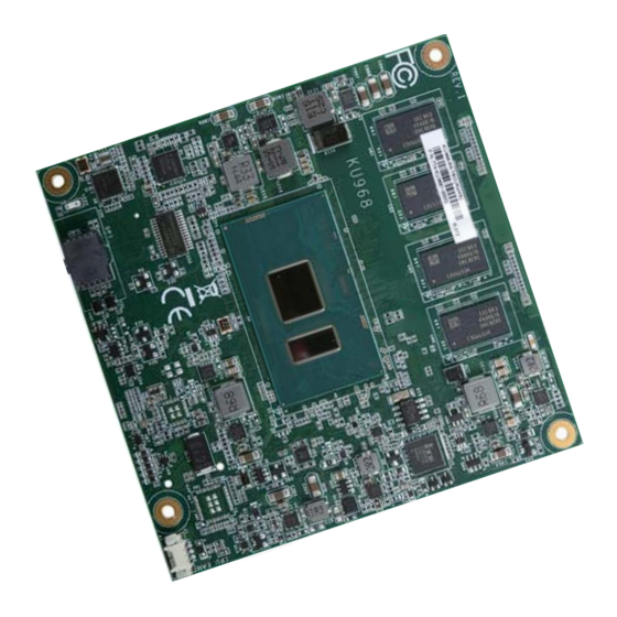
- Page 1 KU968 COM Express Compact Module User’s Manual A45600815 Chapter 1 Introduction www.dfi .com...
-
Page 2: Copyright
Copyright FCC and DOC Statement on Class B This publication contains information that is protected by copyright. No part of it may be re- This equipment has been tested and found to comply with the limits for a Class B digital produced in any form or by any means or used to make any transformation/adaptation without device, pursuant to Part 15 of the FCC rules. -
Page 3: Table Of Contents
Table of Contents Installing KU968 onto a Carrier Board ..........22 Installing the COM Express Debug Card ..........24 Copyright ......................2 Trademarks ......................2 COM Express Specification Reference ........... 2 FCC and DOC Statement on Class B ............. 2 Warranty ...................... -
Page 4: Warranty
Warranty Static Electricity Precautions 1. Warranty does not cover damages or failures that arised from misuse of the product, It is quite easy to inadvertently damage your PC, system board, components or devices even inability to use the product, unauthorized replacement or alteration of components and before installing them in your system unit. -
Page 5: About The Package
About the Package The package contains the following items. If any of these items are missing or damaged, please contact your dealer or sales representative for assistance. • One KU968 board • One heat sink (Height: 23.8mm) Optional Items •... -
Page 6: Chapter 1 - Introduction
Chapter 1 Chapter 1 - Introduction Specifications SYSTEM Processor 7th Generation Intel ® Core Processors, BGA 1356 WATCHDOG Output & System Reset, Programmable via Software from 1 to 255 Seconds TIMER Intel ® Core i7-7600U Processor, Dual Core, 4M Cache, 2.8GHz (3.9GHz), 15W Interval Intel ®... -
Page 7: Features
Chapter 1 Features • Watchdog Timer The Watchdog Timer function allows your application to regularly “clear” the system at the set time interval. If the system hangs or fails to function, it will reset at the set time interval so that your system will continue to operate. -
Page 8: Chapter 2 - Concept
Chapter 2 - Concept COM Express Module Standards The figure below shows the dimensions of the different types of COM Express modules. KU968 is a COM Express Compact module. The dimension is 95mm x 95mm. Common for all Form Factors Extended only... -
Page 9: Specification Comparison Table
Chapter 2 Specification Comparison Table The table below shows the COM Express standard specifications and the corresponding specifications supported on the KU968 module. Module Pin-out - Required and Optional Features A-B Connector. PICMG ® COM.0 Revision 2.1 COM Express Module Base... -
Page 10: Chapter 3 - Hardware Installation
Chapter 3 Chapter 3 - Hardware Installation Block Diagram Board Layout (optional) CH7517 IT8528VG eDP/DDI /DDI DDI Port 2 LVDS (optional) PTN3460 Intel LPC Bus LPC Bus Top View Serial Port 0,1 BGA 1356 SLP/LID SLP/LID SLP/LID 2GB/4GB DDR4 Memory Down 1.2/2.0 Embedded Channel A... -
Page 11: System Memory
Chapter 3 Important: System Memory DDR4 DDR4 DDR4 DDR4 Electrostatic discharge (ESD) can damage your board, processor, disk drives, add-in boards, and other components. Perform installation procedures at an ESD workstation only. If such a station is not available, you can provide some ESD protection by wear- ing an antistatic wrist strap and attaching it to a metal part of the system chassis. -
Page 12: Connectors
Chapter 3 Connectors COM Express Connectors The COM Express connectors are used to interface the KU968 COM Express board to a carrier CPU Fan Connector board. Connect the COM Express connectors (located on the solder side of the board) to the COM Express connectors on the carrier board. -
Page 13: Com Express Connectors
Chapter 3 COM Express Connectors Row A Row B Row A Row B Row C Row D Row C Row D GND (FIXED) GND (FIXED) PCIE_TX4- PCIE_RX4- GND (FIXED) GND (FIXED) GBE0_MDI3- GBE0_ACT# GPO2 TYPE1# TYPE2# GBE0_MDI3+ LPC_FRAME# PCIE_TX3+ PCIE_RX3+ USB_SSRX0- USB_SSTX0- GBE0_LINK100#... -
Page 14: Com Express Connectors Signal Discription
I/O Bi-directional input / output signal OD Open drain output AC97/HDA Signals Descriptions Signal Pin# Module Pin Type Pwr Rail /Tolerance KU968 Carrier Board Description AC/HDA_RST# O CMOS 3.3V Suspend/3.3V Connect to CODEC pin 11 RESET# Reset output to CODEC, active low. - Page 15 Chapter 3 PCI Express Lanes Signals Descriptions Signal Pin# Module Pin Type Pwr Rail /Tolerance KU968 Carrier Board Description PCIE_TX0+ AC Coupling capacitor O PCIE AC coupled on Module Connect to PCIE device or slot PCI Express Differential Transmit Pairs 0...
- Page 16 Chapter 3 PEG Signals Descriptions Signal Pin# Module Pin Type Pwr Rail /Tolerance KU968 Carrier Board Description PEG_TX9+ O PCIE AC coupled on Module PCI Express Graphics transmit differential pairs 9 PEG_TX9- PEG_RX9+ I PCIE AC coupled off Module PCI Express Graphics receive differential pairs 9...
- Page 17 Chapter 3 DDI Signals Descriptions Signal Pin# Module Pin Type Pwr Rail /Tolerance KU968 Carrier Board Description DDI2_PAIR2+ Connect AC Coupling Capacitors 0.1uF to Device O PCIE AC coupled off Module DDI 2 Pair 2 differential pairs DDI2_PAIR2- Connect AC Coupling Capacitors 0.1uF to Device DDI2_PAIR3+ Connect AC Coupling Capacitors 0.1uF to Device...
- Page 18 Chapter 3 USB Signals Descriptions Signal Pin# Module Pin Type Pwr Rail /Tolerance KU968 Carrier Board Description USB_SSRX1+ Connect 90 @100MHz Common Choke in series and ESD suppressors to GND to USB I PCIE AC coupled off Modul Additional receive signal differential pairs for the SuperSpeed USB data path.
- Page 19 SPI Signals Descriptions Signal Pin# Module Pin Type Pwr Rail /Tolerance KU968 Carrier Board Description Selection straps to determine the BIOS boot device. The Carrier should only float these or pull them low, please refer to COM Express Module Base Specification Revision 2.1 for strapping options of BIOS disable signals.
- Page 20 Chapter 3 Power and System Management Signals Descriptions Signal Pin# Module Pin Type Pwr Rail /Tolerance KU968 Carrier Board Description SUS_STAT# O CMOS 3.3V Suspend/3.3V Indicates imminent suspend operation; used to notify LPC devices. Indicates system is in Suspend to RAM state. Active low output. An...
-
Page 21: Standby Power Led
Bottom View of the Heat Sink • “1” denotes the location of the thermal pad designed to contact the corresponding components that are on the KU968. Important: Remove the plastic covering from the thermal pads prior to mounting the heat sink onto the KU968. - Page 22 KU968 1. Grasp KU968 by its edges and position it on top of the carrier board with the mounting holes of KU968 aligning with the standoffs on the carrier board. This will also align the COM Express connectors of the two boards to each other.
- Page 23 Chapter 3 3. Use the provided mounting screws to secure KU968 with heat sink to the carrie board. The photo below shows the locations of the long mounting screws. Long screws Chapter 3 Hardware Installation www.dfi .com...
- Page 24 Chapter 3 Installing the COM Express Debug Card 2. Connect the COMe-DEBUG card to COMe-LINK1 via a cable. COMe-DEBUG Note: The system board used in the following illustrations may not resemble the actual board. These illustrations are for reference only. Code Review Port 80 Display Control...
- Page 25 Carrier Board COMe-DEBUG 4. Then use the instructions from the previous section to install SU968 and heat sink on the top of the COMe-LINK1 debug card. KU968 COMe-LINK1 Carrier Board Side View of the Module, Debug Card and Carrier Board Chapter 3 Hardware Installation www.dfi...
Need help?
Do you have a question about the KU968 and is the answer not in the manual?
Questions and answers