
Related Manuals for CET iMeter 6


Summary of Contents for CET iMeter 6
- Page 1 6 Advanced Power Quality Analyzer User Manual Version: V1.0A September 24, 2019...
- Page 2 The information contained in this Manual is believed to be accurate at the time of publication; however, CET assumes no responsibility for any errors which may appear here and reserves the right to make changes without notice. Please consult CET or your local representative for latest product specifications.
- Page 3 DANGER Failure to observe the following instructions may result in severe injury or death and/or equipment damage. ➢ Installation, operation and maintenance of the meter should only be performed by qualified, competent personnel that have the appropriate training and experience with high voltage and current devices. The meter must be installed in accordance with all local and national electrical codes.
- Page 4 This warranty is on a return to factory for repair basis. ➢ CET does not accept liability for any damage caused by meter malfunctions. CET accepts no responsibility for the suitability of the meter to the application for which it was purchased.
-
Page 5: Table Of Contents
Table of Contents Chapter 1 Introduction ............................1 1.1 Overview ..............................1 1.2 Features ..............................1 1.3 iMeter 6’s Application in Power and Energy Management Systems............4 1.4 Getting more information ......................... 4 Chapter 2 Installation.............................. 5 2.1 Appearance ............................... 5 2.2 Unit Dimensions............................ - Page 6 CET Electric Technology 4.4 Setpoints ..............................62 4.5 Logical Module ............................64 4.6 Logging ..............................65 4.6.1 Max./Min. Log ..........................65 4.6.2 Peak Demand Log ........................65 4.6.3 Interval Energy Recorder (IER) Log ....................65 4.6.4 Waveform Recorder (WFR) Log ....................66 4.6.5 PQ Log ............................
- Page 7 CET Electric Technology 5.12 Meter Information ..........................105 Appendix A – Data Recorder Parameter ......................106 Appendix B – Data Recorder Default Settings ..................... 109 Appendix C – SOE Event Classification ........................ 111 Appendix E – Technical Specifications ........................ 115 Appendix F –...
-
Page 8: Chapter 1 Introduction
This chapter provides an overview of the iMeter 6 meter and summarizes many of its key features. 1.1 Overview The iMeter 6 is CET’s latest offer for the advanced Power Quality Monitoring of Incomers and Critical Feeders for Utilities, Data Centers, High-Tech Manufacturing Facilities and Heavy Industries. Housed in an industry-standard DIN form factor measuring 96mmx96mmx119.5mm, the iMeter 6’s compact size is perfectly suited for today’s... - Page 9 CET Electric Technology Demands ▪ Demands and Predicted Demands for 3-Phase Voltage, Current, Power, PF, I4, Frequency, U and I Unbalance and THD ▪ Peak Demands with Timestamp for Current, Power, and PF of This Month and Last Month (or Since Last Reset and Before Last Reset) ▪...
- Page 10 ▪ Battery-backed Real-time Clock with 6ppm accuracy (<0.5s per day) System Integration ▪ Supported by CET’s PecStar® iEMS ▪ Easy integration into other Automation or SCADA systems via Modbus RTU and Modbus TCP protocols ▪ The on-board, password protected Web Server allows access to its data and supports the configuration for...
-
Page 11: Imeter 6'S Application In Power And Energy Management Systems
1.3 iMeter 6’s Application in Power and Energy Management Systems The iMeter 6 can be used to monitor Wye or Delta connected power system. Modbus communications allow real-time data, events, DI status, Data Logs, Waveform and other information to be transmitted to an Integrated Energy Management System such as PecStar®... -
Page 12: Chapter 2 Installation
Chapter 2 Installation Caution Installation of the iMeter 6 should only be performed by qualified, competent personnel that have the appropriate training and experience with high voltage and current devices. The meter must be installed in accordance with all local and national electrical codes. -
Page 13: Unit Dimensions
CET Electric Technology 2.2 Unit Dimensions Figure 2-3 Unit Dimensions 2.3 Terminal Dimensions Terminal Terminal Dimensions Wire Size Max. Torque 2.6mm x 3.3mm Power Supply RS485 5 kgf.cm/M3 1.5mm (4.3 lb-in) 2.6mm x 3.2mm I4 Input Voltage Input 1.0mm - 2.5mm 18.0 kgf.cm/M4... -
Page 14: Mounting
CET Electric Technology 2.4 Mounting The iMeter 6 should be installed in a dry environment with no dust and kept away from heat, radiation and electrical noise sources. Installation steps: ▪ Remove the mounting slide bars from the meter ▪... -
Page 15: 3-Phase 4-Wire Wye Direct Connection With 3Cts Or 4Cts
CET Electric Technology 2.5.2 3-Phase 4-Wire Wye Direct Connection with 3CTs or 4CTs Please consult the serial number label to ensure that the rated system phase voltage is less than or equal to the meter’s rated Phase voltage input specification. Set the Wiring Mode to 3P4W. -
Page 16: 3-Phase 3-Wire Direct Delta Connection With 3Cts Or 2Cts
2.6.1 RS485 Port The iMeter 6 provides one RS485 port and supports the Modbus RTU protocol. Up to 32 devices can be connected on a RS485 bus. The overall length of the RS485 cable connecting all devices should not exceed 1200m. -
Page 17: Ethernet Port (10/100Baset)
The following figure illustrates the Digital Input connections on the iMeter 6: Figure 2-15 DI Connections 2.8 GPS 1PPS Input wiring The Digital Input on the iMeter 6 can be used for time synchronization with a GPS 1PPS output. The following figure illustrates the wiring connections: Figure 2-16 Time Sync. Connections 2.9 Digital Output Wiring... -
Page 18: Analog Input Wiring
CET Electric Technology 2.11 Analog Input Wiring The following figure illustrates the optional Analog Input connections. Figure 2-19 AI Connections 2.12 Power supply Wiring For AC supply, connect the live wire to the L/+ terminal and the neutral wire to the N/- terminal. -
Page 19: Chapter 3 User Interface
Table 3-1 Font Panel LED Indicators 3.1.2 Front Panel Buttons The iMeter 6 provides four buttons, < >, <>, < > and <> for data display and setup configuration. The following table describes the basic functions for each button: Button Description ... - Page 20 CET Electric Technology The following figure provides an overview of the Front Panel User Interface. Figure 3-2 Overview for Front Panel Operation 3.1.3.1 Metering The Metering menu consists of Phasor, Voltage, Current, Power, Energy, Demand, TOU, Max. & Min. and I/O. The following sections provide an overview of this sub-menu.
- Page 21 CET Electric Technology 3.1.3.1.2 Voltage Enter the Voltage sub-menu and the following screens are available. Use the <> button to scroll to the different displays for 3Φ Uln, 3Φ Ull, Average and Frequency. Figure 3-5 Voltage Measurements 3.1.3.1.3 Current Enter the Current sub-menu and the following screens are available. Use the <> button to scroll to the different displays for 3Φ...
- Page 22 CET Electric Technology 3.1.3.1.5 Energy Enter the Energy sub-menu and the following screens are available. Use the <> button to scroll to the different displays for kWh, kvarh Import/Export/Net/Total and kVAh Total. Figure 3-8 Energy Measurements 3.1.3.1.6 Demand Enter the Demand sub-menu and the following screens are available. Use the < > button to scroll among Present Demand, Predicted Demand, This Max.
- Page 23 CET Electric Technology 3.1.3.1.8 Max. & Min. Enter the Max. & Min. sub-menu and the following screens are available. Use the < > button to scroll between Max. and Min. Use the <> button to scroll to the different Max. & Min. measurements with timestamps. Table 4-16 Max./Min.
- Page 24 CET Electric Technology 3.1.3.2.1 Harmonics Enter the Harmonics sub-menu and the following screens are available. Use the < > button to scroll between the Harmonic Spectrum for the 3Φ Voltages and Currents. • Press < > to view the THD, TOHD, TEHD and Crest Factor measurements and use the <> button to view the TDD, TDD Odd, TDD Even and K-Factor measurements for Currents.
- Page 25 CET Electric Technology 3.1.3.2.4 Unbalance Enter the Unbalance sub-menu and the following screen appears which displays the Negative (U2/I2) and Zero (U0/I0) Sequence Unbalance measurements for Voltage and Current. Figure 3-18 Unbalance 3.1.3.2.5 Sequence Enter the Sequence sub-menu and the following screen appears which display the Positive (U1/I1), Negative (U2/I2) and Zero (U0/I0) Sequence Components for Voltage and Current.
- Page 26 CET Electric Technology 3.1.3.4 Events The Events menu consists of SOE Log, PQ Log and PQ Counters. The following section provides a quick overview of these screens. Figure 3-22 Events Menu 3.1.3.4.1 SOE Log Enter the SOE Log sub-menu and the following screens are available. The SOE Log screen starts with the most recent events.
- Page 27 CET Electric Technology 3.1.3.4.3 PQ Counters Enter the PQ Counters sub-menu and the following screen appears which displays the different PQ Event counters. Figure 3-25 PQ Counters 3.1.3.5 Setup The Setup menu consists of Basic, Demand & Energy, Comm., I/O, Clock, Password, HMI, Maintenance, and Device Info.
- Page 28 CET Electric Technology 3.1.3.5.2 Demand & Energy Enter the Demand & Energy sub-menu and following screens are available. Use the < > button to scroll between Demand and Energy. Please refer to Section 3.2.3.5.3 for more information about the different parameters.
- Page 29 CET Electric Technology 3.1.3.5.6 Password Enter the Password sub-menu and the following screen appears which allows the Front Panel Password to be modified. Figure 3-32 Password Setting 3.1.3.5.7 HMI Enter HMI sub-menu and the following screen appear. Figure 3-33 HMI Settings 3.1.3.5.8 Maintenance...
-
Page 30: On-Board Web Interface
Table 3-3 Web Browser Supported The default IP Address of the iMeter 6’s Ethernet Port is 192.168.0.100. Please make sure to configure the IP Address, Subnet Mask and Default Gateway such that it’s on the same subnet as the PC that is being used to connect with the iMeter 6. -
Page 31: Configure Imeter 6'S Ip Address
Figure 3-39 Setting iMeter 6’s IP address 3.2.3 Accessing Web Interface Enter the IP Address of the iMeter 6 in the Address area of Google Chrome and then press <Enter>. Figure 3-40 Web Logon The iMeter 6’s logon page appears. - Page 32 CET Electric Technology The iMeter 6’s Web Interface appears after login. There are five items at the Title Bar – PQ Insight, Metering, Power Quality, Events and Setup. Figure 3-43 Title Bar The Web Interface’s login password can be changed by clicking user at the upper right-hand corner of the page and then selecting Change Password as shown below.
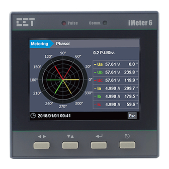
- Page 33 CET Electric Technology 3.2.3.2 Metering Click Metering at the Title Bar and its sub-menu appears on the left-hand pane which includes Phasor, Basic, Energy, Demand, TOU, Max./Min. and I/O. The following sections provide an overview for these sub-menus. 3.2.3.2.1 Phasor Click Phasor on the left-hand pane and the following screen appears which displays the Magnitude and Phase information for Ua/Ub/Uc (3P4W) or Uab/Ubc/Uca (3P3W) and Ia/Ib/Ic.
- Page 34 CET Electric Technology 3.2.3.2.3 Energy Click Energy on the left-hand pane and the following screen appears which shows the Active and Reactive Energy for Import/Export/Net/Total as well as the Total Apparent Energy for the total of 3 Phases. Click Phase A/B/C to view the Energy information for the individual phases.
- Page 35 CET Electric Technology 3.2.3.2.5 TOU Click TOU on the left-hand pane to view the present TOU information for all 8 Tariffs. The Present Tariff, Present Season and Present Daily Profile are displayed at the top of the page. Select from the drop-down list underneath Present Tariff to display the respective Tariff information for kWh Import, kWh Export, kvarh Import, kvarh Export and kVAh.
- Page 36 CET Electric Technology 3.2.3.2.7 I/O Click I/O on the left-hand pane and the following screen appears which displays the status or measurements for DI, DO and AI (Optional). Figure 3-52 I/O Display 3.2.3.3 Power Quality Click Power Quality at the Title Bar and its sub-menu appears on the left-hand pane which includes Harmonics, Deviation, and Unb.
- Page 37 CET Electric Technology Click Individual Harmonics at the bottom of the page to view the data in a Table format. Figure 3-54 Individual Harmonic Measurements 3.2.3.3.2 Deviation Click Deviation on the left-hand pane and the following screen appears which displays the Over/Under Deviation measurements for Ua, Ub, Uc, Uab, Ubc and Uca as well as the Frequency Deviation.
- Page 38 CET Electric Technology 3.2.3.4 Events Click Events at the Title Bar and its sub-menu appears on the left-hand pane which includes SOE, PQ Log and PQ Counter. The following sections provide a quick overview of these web pages. 3.2.3.4.1 SOE Click SOE on the left-hand pane and the following screen appears on the right-hand pane.
- Page 39 CET Electric Technology 2) WFR #1 Triggered by Comm. Figure 3-59 SOE Detail about WFR #1 Triggered by Comm. Inside the waveform display, there are four control icons These two icons are used to zoom in and out of the waveforms based on the time scale.
- Page 40 CET Electric Technology Figure 3-61 PQ Log Interface 3.2.3.4.3 PQ Counters Click PQ Counters on the left-hand pane and the following screen appears on the right-hand pane. This web page displays the counters for the different PQ events such as Dips, Swells, Interruptions, and Transients.
- Page 41 CET Electric Technology 3.2.3.5 Setup Click Setup at the Title Bar and its sub-menu appears on the left-hand pane which includes Basic, PQ, Dmd. & Energy, Record, Setpoint, I/O, Others and Diagnostics. 3.2.3.5.1 Basic Click Basic on the left-hand pane and the following screen appears which has the four tabs: Basic, Comm., Time and Others.
- Page 42 Click Time at the top of the right-hand pane and the following screen appears. This web page shows two areas: Date and Time Sync. The Sync. With PC check box can be used to synchronize the iMeter 6’s Clock with the PC Clock with just a simple click.
- Page 43 CET Electric Technology • Others Click Others at the top of the right-hand pane and the following screen appears which allows the users to setup Language and Delimiter. Figure 3-66 Basic-> Others Setup Interface The following table illustrates the setup range for the Language and Delimiter parameters where * indicates the default value.
- Page 44 CET Electric Technology Figure 3-68 Trigger 1 / 2 Options The following table illustrates the setup range for Dip/Swell parameters where * indicates the default value. Parameter Description Options/Value, Default* Enable Dip/Swell Detection Enable Enable* / Disable Dip Threshold Specify the Dip threshold as a percentage of Ull nominal...
- Page 45 CET Electric Technology 3.2.3.5.3 Dmd. & Energy Click Dmd. & Energy on the left-hand pane to expand its sub-menu, which includes Demand, Energy and TOU. 3.2.3.5.3.1 Demand Figure 3-70 Demand Setup Interface The following table illustrates the setup range for Demand parameters where * indicates the default value.
- Page 46 CET Electric Technology 3.2.3.5.3.2 Energy Click Energy on the left-hand pane and the following screen appears which allows the setup parameters for Interval Energy, Energy Preset, Energy Pulse and IER (Interval Energy Recorder) to be configured. • Interval Energy allows the configuration of EN Period, which has a range of 5 to 60 minutes (default = 60 min).
- Page 47 CET Electric Technology • Energy Pulse supports the configuration of the LED EN Pulse and Pulse Constant setup parameters. Figure 3-73 Energy Pulse Setup Interface The following table illustrates the range of Energy Pulse setup parameters where * indicates the default value.
- Page 48 CET Electric Technology 3.2.3.5.3.3 TOU Click TOU on the left-pane and the following screen appears which allows the TOU setup parameters to be configured. The 4 tabs are Basic, Daily Profiles, Seasons and Alternate Days. Please refer to Section 4.6.8 for more information.
- Page 49 CET Electric Technology Figure 3-77 TOU – DP1 Setting Dialog • Seasons Figure 3-78 TOU – Seasons Click Seasons and the above screen appears which allows the Start Date, Weekday 1 DP, Weekday2 DP and Weekday 3 DP each Season to be defined until the entire year has been filled. Up to 12 seasons can be defined for each TOU.
- Page 50 Click Record on the left-hand pane to expand its sub-menu which includes Waveform and DR (Data Recorder). 3.2.3.5.4.1 Waveform The iMeter 6 provides 2 independent groups of Waveform Recorders (WFR) with 128 entries each. Click on WFR1 or WFR2 to access their configurations. Please refer to Section 4.6.4 for more details.
- Page 51 CET Electric Technology • WFR1 (Waveform Recorder 1) Figure 3-81 Record – WFR1 Setup Interface • WFR2 (Waveform Recorder 2) Figure 3-82 Record – WFR2 Setup Interface...
- Page 52 CET Electric Technology 3.2.3.5.4.2 DR (Data Recorder) The iMeter 6 provides 4 High-Speed Data Recorders (HS DR) as well as 12 Standard Data Recorders (DR) capable of recording up to 16 parameters each. Please refer to Section 4.6.7 for more information.
- Page 53 CET Electric Technology 3.2.3.5.5 Setpoint Click Setpoint on the left-hand pane and the following screen appears which allows the setup parameters for Setpoint (Standard Setpoint), HSSP (High-speed Setpoint) and Logical Module to be configured as required. Please refer to Sections 4.4 and 4.5 for more information.
- Page 54 CET Electric Technology • HS Setpoint Figure 3-87 Setpoint – HSSP Settings Click on a particular HS Setpoint and the HSSP Settings dialog box appears. Up to 14 parameters are available for the HS Setpoint monitoring, including Uln, Ull, I, I4, Frequency Deviation, kW/kvar total, PF, DI1 to DI6 Status.
- Page 55 Figure 3-89 Setpoint – Logical Module Settings The iMeter 6 comes standard with 6 programmable Logical Modules. Click on a particular module and the Logical Module Settings dialog box appears which allows up to 4 logical operations to be configured with AND, OR, NAND, or NOR.
- Page 56 CET Electric Technology 3.2.3.5.6 I/O Setup Click I/O on the left-hand pane and the following screen appears which allows the I/O parameters to be configured as required. Please refer to Section 4.1 for more information. • DI Figure 3-91 DI Setup Interface Click on a specific DI and the following dialog box appears.
- Page 57 CET Electric Technology DI Mode = PPS Sync. Figure 3-95 DI PPs Sync. Setup Interface DI Mode = Tariff Switch Figure 3-96 DI Tariff Switch Setup Interface • DO Figure 3-97 DO Setup Interface • AI (Optional) Figure 3-98 Optional AI Setup Interface...
- Page 58 CET Electric Technology 3.2.3.5.7 Others Click Others on the left-hand pane to expand its sub-menus which include Alarm Email & Advanced. 3.2.3.5.7.1 Alarm Email • Settings Please refer to Section 4.8 for more details about the configurations. Figure 3-99 Alarm Email Settings Interface •...
- Page 59 CET Electric Technology 3.2.3.5.7.2 Advanced Click Advanced on the left-hand pane and the following screen appears which allows the IP Port Numbers for the different protocols to be configured. Please consult the qualified personnel before making changes to these parameters.
- Page 60 CET Electric Technology 3.2.3.5.8.2 User Management The user with Operator authority can click to add or remove an existing user account. Figure 3-103 Diagnostics – User Management 3.2.3.5.8.3 Maintenance Click Maintenance on the left-hand pane and the following screen appears which provides the options for DO Control, Clear, Imp./Exp.
- Page 61 CET Electric Technology Figure 3-105 Maintenance – DO Release Command Failed Further, the DO Forced On/Off operations from the Front Panel have the highest priority as discussed in Section 4.1.2 . If a DO is accidentally left in the DO Forced On/Off state without being returned to the Normal state, PQ or other Control Setpoints will no longer be able to trigger it during an alarm situation.
- Page 62 CET Electric Technology • Imp./Exp. Import or Export the System Setup Parameters. Figure 3-107 Maintenance – Imp./Exp. • Upgrade Only a user with Operator authority can perform a firmware upgrade for the iMeter 6. Figure 3-108 Maintenance – Upgrade...
-
Page 63: Chapter 4 Applications
4.1 Inputs and Outputs 4.1.1 Digital Inputs The iMeter 6 comes standard with six self-excited Digital Inputs that are internally wetted at 24 VDC with a sampling frequency of 1000Hz and programmable debounce. The iMeter 6 provides the following programmable... -
Page 64: Energy Pulse Outputs
The pulse constant can be configured as 1000/3200/5000/6400/12800 pulses per kWh or kvarh through the Pulse Constant setup parameters. 4.1.4 Analog Input The iMeter 6 comes optionally with an Analog Input which can be programmed as 0mA to 20mA or 4mA to 20mA input. There are 3 setup parameters: Type: Select between 0-20mA or 4-20mA input. -
Page 65: Energy Measurements
CET Electric Technology 4.2.2 Energy Measurements The iMeter 6 provides Energy parameters for active energy (kWh), reactive energy (kvarh) and apparent energy (kVAh) with a resolution of 0.1 and a maximum value of ±1,000,000,000.00. When the maximum value is reached, the energy registers will automatically roll over to zero. -
Page 66: Max./Min. Per Demand Period
I4 is valid if the meter is equipped with the I4 option, and it will be automatically changed to In (Calculated Neutral Current) if the meter is equipped with the AI option. 4.2.6 Max./Min. per Demand Period The iMeter 6 provides the Max./Min. value per demand period of the following measurements: ▪ 3-Phase Voltage and Frequency ▪... - Page 67 CET Electric Technology 4.3.2.2 Harmonics The following table illustrates the Voltage and Current Harmonic measurements on the iMeter 6. Phase A/AB Phase B/BC Phase C/CA TOHD TOHD TOHD TEHD TEHD TEHD Harmonics-Voltage Crest-factor Crest-factor Crest-factor Harmonic Harmonic Harmonic … Harmonic...
-
Page 68: Unbalance And Sequence Components
4.3.5 Supply Voltage Dips/Swells and Interruptions The iMeter 6 supports the detection of Supply Voltage Dips/Swells and Interruptions using a method that is in accordance with IEC 61000-4-30 for Class S performance. The iMeter 6 provides Dip/Swell and Interruption for voltage quality monitoring on a per phase basis based on ½-cycle and records any detected event in the PQ Log with timestamp and event type. -
Page 69: Transients Voltage
The iMeter 6 provides Transient Capture capability by detecting voltage disturbances with a maximum resolution of 80µs. The iMeter 6 provides transient detection for voltage quality monitoring and records the detected event in the PQ Log with timestamp and event type. The programming of the Transient setpoint is supported via the Web Interface or communications. - Page 70 Please refer to Table 4-12 below for a list of Setpoint Triggers. Table 4-10 Description for Setpoint Parameters The iMeter 6 provides the following Setpoint parameters, Standard Setpoint can monitor all parameters while the HS Setpoint only can monitor parameters 1 to 14.
-
Page 71: Logical Module
Figure 4-3 Phase Reversal Logic Diagram 4.5 Logical Module The iMeter 6 comes standard with 6 user programmable Logical Modules which may be programmed to perform an AND, NAND, OR or NOR logical operation. The Logical Module provides extensive control by allowing a user to initiate an action based on the combinational logic of up to four different Setpoint conditions. -
Page 72: Logging
4.6 Logging 4.6.1 Max./Min. Log The iMeter 6 records the Max. Log and Min. Log of This Month (Since Last Reset) and Last Month (Before Last Reset) with timestamp for the parameters in Table 4-16 Max./Min. Log . Each log includes the relevant parameter value and its timestamp. The recorded data is stored in the device’s non-volatile memory and will not suffer any loss in the event of power failure. -
Page 73: Waveform Recorder (Wfr) Log
Figure 4-4 WFR Log displayed on iMeter 6’s Web Interface 4.6.5 PQ Log The iMeter 6’s PQ Log can store up to 512 PQ events such as Dips/Swells and Transients. Each event record includes the event classification, its relevant voltage values and a timestamp in 1ms resolution. -
Page 74: Time Of Use (Tou)
6 and accumulate energy consumption into different TOU tariffs based on the time of consumption. The TOU feature on iMeter 6 supports two TOU schedules, which can be switched at a pre-defined time. Each TOU schedule supports: ▪... -
Page 75: Time Synchronization
There are several methods to synchronize the iMeter 6’s clock: 1) The Web Interface can be used to set the clock of an individual iMeter 6 manually or through the Sync. with PC function using the computer’s clock as the time source... -
Page 76: Alarm Email
Table 4-23 SNTP Setup Parameters 3) Further, a GPS that has a 1 PPS output can be used to synchronize the millisecond clock through iMeter 6's DI6 Input. The programming of the Digital Input is supported via the Front Panel, Web Interface, or communications. - Page 77 Receiver. However, if the receiver didn’t receive the test email, the Alarm Email settings should be verified to make sure that they are correct, and the iMeter 6 should be checked that it is connected to the Internet. Figure 4-7 Send Test Email...
- Page 78 CET Electric Technology 3. Configure the Thresholds and Hysteresis settings for Dip, Swell and Interruption as shown below. Select the SMTP check box in Trigger 1 or 2. Figure 4-9 Dip, Swell and Interruption Thresholds & Hysteresis Figure 4-10 Trigger 1 Settings 4.
-
Page 79: Ethernet Gateway
3) Configure the IP Port No. (default=6000) and make sure that it matches that of the Modbus Master Software. 4) Please note that the iMeter 6’s Ethernet Gateway is a Transparent Gateway only and not a Modbus TCP to RTU Gateway. -
Page 80: Chapter 5 Modbus Map
6 to facilitate the development of 3 party communications driver for accessing information on the iMeter 6. For a complete Modbus Protocol Specification, please visit http://www.modbus.org. The iMeter 6 supports the following Modbus functions: 1) Read Holding Registers (Function Code 0x03) - Page 81 CET Electric Technology 0082 Float 0084 Reserved UINT16 x100 0085 DI Status UINT16 0086 DO Status UINT16 0087 Alarm Status UINT32 0089 SOE Pointer UINT32 0091 PQ Log Pointer UINT32 0093 WFR Log #1 Pointer UINT32 0095 WFR Log #2 Pointer...
-
Page 82: Energy Measurements
The Energy registers have a maximum value of 1,000,000,000 and will roll over to zero automatically when it is reached. The iMeter 6 also provides energy measurements in fractional values if they are required. Using the “Fractional” registers, having units such as Wsec, varsec and VAsec, the user can obtain decimal resolution for achieving higher accuracy. -
Page 83: Phase B Energy Measurements
CET Electric Technology 4632 kWh Total Fractional Float 4634 kvarh Import Fractional Float 4636 kvarh Export Fractional Float var s 4638 kvarh Net Fractional Float 4640 kvarh Total Fractional Float VA s 4642 kVAh Fractional Float 4644 kvarh Q1 Fractional... -
Page 84: Tou Energy Measurements
CET Electric Technology 4748 kvarh Q1 Fractional Float 4750 kvarh Q2 Fractional Float var s 4752 kvarh Q3 Fractional Float 4754 kvarh Q4 Fractional Float Table 5-6 Phase C Energy Measurements 5.2.5 TOU Energy Measurements Register Property Description Format Scale... -
Page 85: Interval Energy Measurements
CET Electric Technology 4134 kvarh Import of T4 Fractional Float var.s 4136 kvarh Export of T4 Fractional Float 4138 kVAh of T4 Fractional Float VA.s 4140 kWh Import of T5 Fractional Float 4142 kWh Export of T5 Fractional Float 4144... -
Page 86: Thd/Tohd/Tehd Measurements
CET Electric Technology 0430 dkWc Float 0432 dkW Total Float 0434 dkvara Float 0436 dkvarb Float 0438 dkvarc Float 0440 dkvar Total Float 0442 dkVAa Float 0444 dkVAb Float 0446 dkVAc Float 0448 dkVA Total Float 0450 dPFa Float 0452... -
Page 87: Tdd Measurements
CET Electric Technology 0916 Uan (3P4W)/Uab (3P3W) Crest-Factor UINT16 0917 Ubn (3P4W)/Ubc (3P3W) Crest-Factor UINT16 0918 Ucn (3P4W)/Uca (3P3W) Crest-Factor UINT16 0919 Ia Crest-Factor UINT16 0920 Ib Crest-Factor UINT16 0921 Ic Crest-Factor UINT16 Table 5-11 THD/TOHD/TEHD Measurements Notes: I4 THD/TOHD/TEHD and Individual Harmonic Registers are valid only if the device is equipped with the I4 option. Otherwise, they are reserved. -
Page 88: Event Counter
CET Electric Technology 5.6 Event Counter Register Property Description Format Scale Unit 4850 Swell UINT32 4852 UINT32 4854 Interruption UINT32 4856 Transient UINT32 4858 Total UINT32 Table 5-14 Event Counter 5.7 Demand Measurements 5.7.1 Present Demand Register Property Description Format... -
Page 89: Predicted Demand
CET Electric Technology 5.7.2 Predicted Demand Register Property Description Format Scale Unit 1200 INT32 1202 INT32 1204 INT32 1206 Uln average INT32 x100 1208 INT32 1210 INT32 1212 INT32 1214 Ull average INT32 1216 INT32 1218 INT32 1220 INT32 x1000... - Page 90 CET Electric Technology 1428 kWb Max. INT32 1430 kWc Max. INT32 1432 kW Total Max. INT32 1434 kvara Max. INT32 1436 kvarb Max. INT32 1438 kvarc Max. INT32 1440 kvar Total Max. INT32 1442 kVAa Max. INT32 1444 kVAb Max.
-
Page 91: Peak Demand Log Of This Month (Since Last Reset)
CET Electric Technology 1674 Ic THD Min. INT32 1676 U0 Unbalance INT32 1678 I0 Unbalance INT32 1680 Ia Fundamental INT32 1682 Ib Fundamental INT32 x100 1684 Ic Fundamental INT32 Table 5-17 Max./Min. Value per Demand Period Notes: I4 Max./Min. Value per Demands Period is valid only if the device is equipped with the I4 option, and it will be automatically changed to In (Calculated) Demand if the meter is equipped with the AI option. - Page 92 CET Electric Technology 2102~2107 Frequency x100 2108~2113 Uan (3P4W)/Uab (3P3W) THD 2114~2119 Ubn (3P4W)/Ubc (3P3W) THD 2120~2125 Ucn (3P4W)/Uca (3P3W) THD x100 2126~2131 Ia THD 2132~2137 Ib THD 2138~2143 Ic THD 2144~2149 Ia K-Factor 2150~2155 Ib K-Factor x100 2156~2161 Ic K-Factor...
- Page 93 CET Electric Technology 5.8.1.3 Max. Log of Last Month (Before Last Reset) Register Property Description Format Scale Unit 2600~2605 2606~2611 2612~2617 2618~2623 Uln average x100 2624~2629 2630~2635 2636~2641 2642~2647 Ull average 2648~2653 2654~2659 x1000 2660~2665 2666~2671 I average 2672~2677 2678~2683...
-
Page 94: Soe Log
CET Electric Technology 3044~3049 Ia K-Factor 3050~3055 Ib K-Factor 3056~3061 Ic K-Factor 3062~3067 U2 Unbalance 3068~3073 I2 Unbalance 3074~3079 x1000 3080~3085 U0 Unbalance 3086~3091 I0 Unbalance Table 5-24 Min. Log of Last Month (Before Last Reset) Notes: I4 is valid only if the device is equipped with the I4 option, and it will be automatically changed to In (Calculated) if the meter is equipped with the AI option. - Page 95 CET Electric Technology 20105~20119 Event 8 20120~20134 Event 9 20135~20149 Event 10 20150~20164 Event 11 20165~20179 Event 12 … … 27665~27679 Event 512 Table 5-28 PQ Log Offset Properties Description Format Note High-order Byte: Event Classification Table 5-30 PQ Log...
-
Page 96: Log Data Format
Modbus function code 0x14 is used to access to the Energy Log, PQ Log, Data Recorder Log and Waveform Recorder Log. The table below list the file format. Read Reference Request Packet Read Reference Response Packet (Master Station to iMeter 6) (iMeter 6 to Master Station) Slave Address 1 Byte... -
Page 97: Data Recorder Log Data Structure
CET Electric Technology 5.9.3 Data Recorder Log Data Structure Offset Property Description Format Note Parameter 1 INT32 Parameter 2 INT32 … … INT32 Parameter N (N=1 to 16) INT32 High-order Byte: Year 0-99 (Year-2000) +2N+1 UINT16 Low-order Byte: Month 1 to 12... - Page 98 CET Electric Technology Nominal Frequency 6005 UINT16 0=50Hz, 1=60Hz nominal 6006 Port 1 Protocol UINT16 0=Modbus, 1=Gateway 6007 Port 1 Unit ID UINT16 1 to 247 0=1200, 1=2400 6008 Port 1 Baud rate UINT16 2=4800, 3=9600 4=19200, 5=38400 0=8N2, 1=8O1, 2=8E1...
- Page 99 CET Electric Technology 0=None 6076 Dip/Swell Trigger 1 UINT16 1 to 3=DO1 ~ DO3 4 to 7=HS DR 1 ~ 4 8 to 19=Standard DR 1 ~ 12 20 to 21=WR 1 ~ WR 2 6077 Dip/Swell Trigger 2 UINT16...
- Page 100 CET Electric Technology The default Ullnominal = 120V for 69V/120V Input; = 415V for 240V/415V Input; = 690V for 400V/690V Input. The last Octet of the IP Address, Subnet Mask and Gateway can neither be “0000 0000” nor “1111 1111”.
-
Page 101: Setpoint Setup
CET Electric Technology Recommended Pulse Constant settings for the different Line Voltage & Current Inputs Voltage Input Current Input X Value Energy Pulse Constant (X Value) 69V/120V 0=1000 imp/kWh 1=3200 imp/kWh 240V/415V 2=5000 imp/kWh 3=6400 imp/kWh 4=12800 imp/kWh 400V/690V Table 5-37 Pulse Constant The Self-Read Time applies to both the Peak Demand Log as well as the Max./Min. - Page 102 CET Electric Technology 6690~6699 Setpoint #10 (Standard) 6700~6709 Setpoint #11 (Standard) 6710~6719 Setpoint #12 (Standard) 6720~6729 Setpoint #13 (Standard) 6730~6739 Setpoint #14 (Standard) 6740~6749 Setpoint #15 (Standard) 6750~6759 Setpoint #16 (Standard) 6760~6769 Setpoint #17 (High-Speed) 6770~6779 Setpoint #18 (High-Speed) 6780~6789...
-
Page 103: Logical Module Setup
CET Electric Technology U THD x100, % U TOHD x100, % U TEHD x100, % I THD x100, % I TOHD x100, % I TEHD x100, % U2 Unbalance x10, % I2 Unbalance x10, % U OverDeviation x100, % Active/Inactive Limit settings are invalid when Voltage Phase Reversal is set as Voltage Phase Reversal the Setpoint Parameter. -
Page 104: Data Recorder Setup
CET Electric Technology 5.10.3.2 Logical Module Setup Data Structure Register Property Description Format Range Default Enable Logical Module UINT16 0=Disabled, 1=Enabled Mode 1 UINT16 0=AND, 1=OR Mode 2 UINT16 2=NAND, 3=NOR Mode 3 UINT16 Source 1 UINT16 0 to 24... - Page 105 CET Electric Technology 5.10.4.2 High-speed Data Recorder Setup Data Structure Offset Property Description Format Range 0=Disabled Trigged Mode UINT16 1=Triggered by Timer 2=Triggered by Setpoint 0=Stop-When-Full Recording Mode UINT16 1=First-In-First-Out Recording Depth UINT16 0 to 65535 Recording Interval UINT32 1 to 60 (cycles)
-
Page 106: Interval Energy Recorder Setup Registers
Energy Log Pointer to “0”. 5.10.6 Waveform Recorder (WFR) Setup The iMeter 6 provides 2 Waveform Recorders, each with a fixed Recording Depth of 128. Each WFR can simultaneously capture 3-phase Voltage and Current signals at a maximum resolution of 256 samples per cycles. -
Page 107: Tou Setup
5.10.7.2 Season The iMeter 6 has two sets of Season setup parameters, one for each TOU. The Base Addresses for the two sets are 16100 and 17100, respectively, where the Register Address = Base Address + Offset. For example, the register address for TOU #1’s Season #2’s Start Date is 17100+4 = 17104. - Page 108 Season’s duration is from its Start Date to the end of the year. The Start Date of a particular Season must be later than the previous Season’s. 5.10.7.3 Daily Profile The iMeter 6 has two sets of Daily Profile setup parameters, one for each TOU. Register Property...
- Page 109 Alternate Day, its assigned Daily Profile will override the “normal” Daily Profile for this day according the TOU settings. The iMeter 6 has two sets of Alternate Days setup parameters, one for each TOU. The Base Addresses for the two sets are 16700 and 17700, respectively, where the Register Address = Base Address + Offset. For example,...
-
Page 110: Do Control
DO status. The iMeter 6 adopts the ARM before EXECUTE operation for the remote control of its Digital Outputs if this function is enabled through the Arm Before Execute Enable Setup register (6185), which is disabled by default. -
Page 111: Clear/Reset Control
5.11 Time There are two sets of Time registers supported by the iMeter 6 – Year / Month / Day / Hour / Minute / Second (Registers # 60000 to 60002) and UNIX Time (Register # 60004). When sending time to the iMeter 6 over Modbus communications, care should be taken to only write one of the two Time register sets. -
Page 112: Meter Information
9831 Voltage Input UINT16 3=Reserved Table 5-63 Meter Information Notes: The Meter Model appears in registers 9800 to 9819 and contains the ASCII encoding of the string “iMeter 6” as shown in the following table. Register Value(Hex) ANSCII 60200 9800... -
Page 113: Appendix A - Data Recorder Parameter
CET Electric Technology Appendix A – Data Recorder Parameter Parameters Scale/Unit Parameters Scale/Unit x100, V x100, V x100, V Uln average x100, V x100, V x100, V x100, V Ull average x100, V x1000, A x1000, A x1000, A I average... - Page 114 CET Electric Technology Ia 11 Harmonic x100, % Ib 11 Harmonic x100, % Ic 11 Harmonic x100, % Ia 12 Harmonic x100, % Ib 12 Harmonic x100, % Ic 12 Harmonic x100, % Ia 13 Harmonic x100, % Ib 13...
- Page 115 CET Electric Technology x1000, A kWh Import kWh Export kWh Total kvarh Import kvarh kvarh Export kvarh kvarh Total kvarh I Residual x1000, A U0 Unbalance x10, % I0 Unbalance x10, % U0 Unbalance Demand x10, % I0 Unbalance Demand...
-
Page 116: Appendix B - Data Recorder Default Settings
CET Electric Technology Appendix B – Data Recorder Default Settings Parameter DR 1 (HS) DR 2 (HS) DR 3 (HS) DR 4 (HS) Trigger Mode Disabled Disabled Disabled Disabled Recording Mode Stop-When-Full Stop-When-Full Stop-When-Full Stop-When-Full Recording Depth Recording Interval Recording Offset... - Page 117 CET Electric Technology Interval Recording Offset No. of Parameters Uan max per Demand Uan THD max per Uab min per Demand Uan min per Demand Parameter 1 Period Demand Period Period Period Ubn max per Demand Ubn THD max per...
-
Page 118: Appendix C - Soe Event Classification
CET Electric Technology Appendix C – SOE Event Classification Event Sub- Event Value Description Classification Classification Scale/Option 1 / 0 DI1 Close/DI1 Open 1 / 0 DI2 Close/DI2 Open 1 / 0 DI3 Close/DI3 Open 1=DI Changes 1 / 0... - Page 119 CET Electric Technology Return Value Over kW Total Predicted Setpoint Return Return Value Over kvar Total Predicted Setpoint Return Return Value (x1000) Over PF Total Predicted Setpoint Return Return Value (x100) Over Voltage THD Setpoint Return Return Value (x100) Over Voltage TOHD Setpoint Return...
- Page 120 CET Electric Technology Return Value (x100) Under Voltage OverDeviation Setpoint Return Reserved Return Value (x1000) Under Ir Setpoint Return Return Value (x100) Under U2 (Negative Sequence Voltage) Setpoint Return Return Value (x100) Under U0 (Zero Sequence Voltage) Setpoint Return Over Logical Module #1 Setpoint Active...
- Page 121 CET Electric Technology On-board Web Server, 3=Front Panel. 4. The value of the Other events 3~4, 9~10 and 15 illustrates the Setpoint module which triggers the recorder/alarm: 1 to 16 represent the standard setpoint 1 to 16, 17 to 24 represent the high-speed setpoint 1 to 8 and 25 to 30 represent the Logical Module 1 to 6.
-
Page 122: Appendix E - Technical Specifications
CET Electric Technology Appendix D – Technical Specifications Voltage Inputs (V1, V2, V3, VN) Standard (Un) 240VLN/415VLL Optional (Un) 69VLN/120VLL, 400VLN/690VLL Range 10% to 120% Un PT Ratio 1-10,000 Overload 1.2xUn continuous, 2xUn for 10s Burden <0.5VA @ 240V Frequency... -
Page 123: Appendix F - Standards Compliance
CET Electric Technology Appendix E – Standards Compliance Safety Requirements CE LVD Directive 2014 / 35 / EU EN61010-1: 2010 EN61010-2-030: 2010 Electrical safety in low voltage distribution systems up to 1000Vac and 1500 IEC 61557-12: 2018 (PMD) Insulation IEC 62052-11: 2003... -
Page 124: Appendix G - Ordering Guide
CET Electric Technology Appendix F – Ordering Guide... - Page 125 CET Electric Technology Contact Us CET Electric Technology Inc. Tel: +86.755.8341.5187 Fax: +86.755.8341.0291 sales@cet-global.com www.cet-global.com...
Need help?
Do you have a question about the iMeter 6 and is the answer not in the manual?
Questions and answers