Table of Contents
Advertisement
Quick Links
1
Introduction
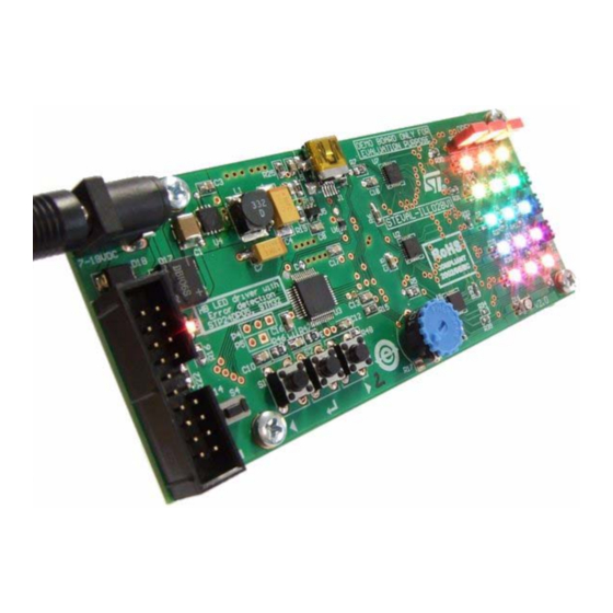
This user manual describes STMicroelectronics™ STEVAL-ILL028V1 LED dimmer board.
This board is based on STP1612PW05 independent PWM LED driver controlled through
STM32 microcontroller SPI interface and DMA (optional).
This document explains how to use the board: hardware setup, demonstration firmware
functions, possible interconnections with PC and evaluation of STP1612PW05.
Figure 1.
July 2010
www.BDTIC.com/ST
STEVAL-ILL028V1 LED dimmer board
using STP1612PW05 and STM32
STEVAL-ILL028V1 LED dimmer board
Doc ID 16881 Rev 2
UM0882
User manual
1/20
www.st.com
™
Advertisement
Table of Contents

Related Manuals for STMicroelectronics STEVAL-ILL028V1


Summary of Contents for STMicroelectronics STEVAL-ILL028V1
-
Page 1: Introduction
™ using STP1612PW05 and STM32 Introduction This user manual describes STMicroelectronics™ STEVAL-ILL028V1 LED dimmer board. This board is based on STP1612PW05 independent PWM LED driver controlled through STM32 microcontroller SPI interface and DMA (optional). This document explains how to use the board: hardware setup, demonstration firmware functions, possible interconnections with PC and evaluation of STP1612PW05. -
Page 2: Table Of Contents
Contents UM0882 Contents Introduction ..........1 Board function overview . - Page 3 UM0882 List of tables List of tables Table 1. Bill of material ............17 Table 2.
- Page 4 STEVAL-ILL028V1 LED dimmer board ........
-
Page 5: Board Function Overview
UM0882 Board function overview Board function overview The STEVAL-ILL028V1 demonstration board features: ● Three STP1612PW05 (QFN24 4 x 4 mm) connected to 16 RBG LEDs ● 16 RGB high brightness LEDs ● One STM32 microcontroller using internal HS oscillator ●... -
Page 6: Hardware Setup
Hardware setup UM0882 Hardware setup The main board components are shown on Figure Figure 2. Setup of the board Power supply The board is powered by a 7.5 to 18 V DC voltage. The power source must be able to deliver a 0.7 A current. -
Page 7: Description Of The Demonstration Firmware Functions
UM0882 Description of the demonstration firmware functions Description of the demonstration firmware functions The main features of the firmware are: ● Brightness control for each LED ● Color control for each LED ● Error detection to detect LED failure ● Simulation Tetris game. -
Page 8: Mode "A" - Interactive Demonstration - Color Tetris
Description of the demonstration firmware functions UM0882 Mode “A” - interactive demonstration - color Tetris Mode 'A' performs a simple interactive demonstration similar to Tetris game. The game starts with a green brick moving from the bottom to the top of the LED area. The brick position can be controlled by using the right and left buttons. -
Page 9: Pc Demonstration Firmware Software
Disconnect the power supply from the board. Connect the board to the computer through the USB cable. Connect the board to the power supply. If Windows asks for the installation of an appropriate driver, use STMicroelectronics VirtualCOMPort. Doc ID 16881 Rev 2 9/20 www.BDTIC.com/ST... -
Page 10: Figure 7. Usb Host (Pc) Detection In Progress
PC demonstration firmware software UM0882 Figure 7. USB host (PC) detection in progress Figure 8. USB host (PC) detected Figure 9. USB host (PC) not found Run SWforDimmer.exe. If the board is not detected automatically, click “Find board on COM port” on the menu as shown in Figure 10/20... -
Page 11: Figure 10. Manual Board Connection
UM0882 PC demonstration firmware software Figure 10. Manual board connection If the board has been found and connected successfully, the message ''Board found on COM4” is displayed in green as depicted on Figure Figure 11. Board connected successfully Doc ID 16881 Rev 2 11/20 www.BDTIC.com/ST... -
Page 12: Figure 12. Error Detection Mode Performed
PC demonstration firmware software UM0882 To perform error detection, click “Perform error detection”. Error detection is performed correctly and does not depend on the board operating mode. Figure 12. Error detection mode performed The evaluation of the error detection through the USB interface: Jumpers P20, P21 and P22 are closed and the jumpers P1, P2 and P3 are open, the PC demonstration software will not report any LED defect after clicking ”Perform error detection”. -
Page 13: Schematics
UM0882 Schematics Schematics Figure 13. Connectors, buttons, UART Doc ID 16881 Rev 2 13/20 www.BDTIC.com/ST... -
Page 14: Figure 14. Microcontroller, Usb, Power Supply
Schematics UM0882 Figure 14. Microcontroller, USB, power supply 14/20 Doc ID 16881 Rev 2 www.BDTIC.com/ST... -
Page 15: Figure 15. High Brightness Leds
UM0882 Schematics Figure 15. High brightness LEDs Doc ID 16881 Rev 2 15/20 www.BDTIC.com/ST... -
Page 16: Figure 16. Led Drivers
Schematics UM0882 Figure 16. LED drivers 16/20 Doc ID 16881 Rev 2 www.BDTIC.com/ST... -
Page 17: Bill Of Material
UM0882 Bill of material Bill of material Table 1. Bill of material Reference Comment Description Footprint 4.7 µF (10 µF) Tantal capacitor polarized 1812LH 470 nF Capacitor 0805 100 nF Capacitor 0805 100 µF (47 µF) size D, 16 V Tantal capacitor polarized 7343_LH 4.7 nF Capacitor... - Page 18 Bill of material UM0882 Table 1. Bill of material (continued) Reference Comment Description Footprint 1.2 kΩ Resistor 0805 R20, R22, 10 KΩ Resistor 0805 100 KΩ Resistor 0805 27 Ω R30 - R45 Resistor 0603LH R46, R47, 100 Ω Resistor 0805 Left Button...
-
Page 19: Revision History
UM0882 Revision history Revision history Table 2. Document revision history Date Revision Changes 12-Mar-2010 Initial release. 08-Jul-2010 Updated Section 2: Board function overview. Doc ID 16881 Rev 2 19/20 www.BDTIC.com/ST... - Page 20 Please Read Carefully: Information in this document is provided solely in connection with ST products. STMicroelectronics NV and its subsidiaries (“ST”) reserve the right to make changes, corrections, modifications or improvements, to this document, and the products and services described herein at any time, without notice.
Need help?
Do you have a question about the STEVAL-ILL028V1 and is the answer not in the manual?
Questions and answers