Table of Contents
Advertisement
Advertisement
Table of Contents

Related Manuals for Laguna Tools MJOIN 8012-0130


Summary of Contents for Laguna Tools MJOIN 8012-0130
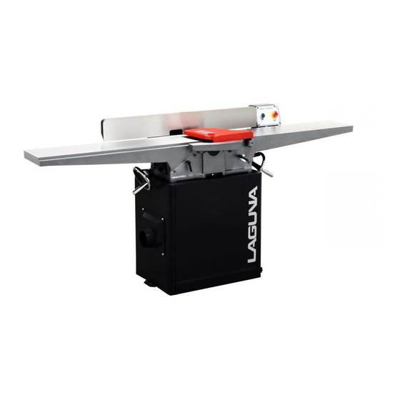
- Page 1 Laguna Tools 8" MJOIN 8012-0130 Jointer manual.
- Page 2 Dear Woodworker: Thank you for your purchase and welcome to the Laguna Tools group of discriminating woodworkers. I understand that you have a choice of where to purchase your machines and appreciate the confidence you have in our products. Every machine sold by Laguna Tools has been carefully designed and well thought through from a woodworkers perspective.
-
Page 3: Table Of Contents
contents Table of Page number Safety Rules Warranty Noise emission Specification sheet Receiving your jointer Introduction to your jointer What you receive with jointer Parts of the jointer Where to locate your jointer Unpacking your jointer Assembly and set up Running &... -
Page 4: Safety Rules
Safety Rules As with all machinery there are certain hazards involved with the operation and use. Using it with caution will considerably lessen the possibility of personal injury. However, if normal safety precautions are overlooked or ignored, personal injury to the operator may result. If you have any questions relative to the installation and operation, do not use the equipment until you have contacted your supplying distributor. -
Page 5: Warranty
Limited Warranty New woodworking machines sold by Laguna Tools carry a one-year warranty from the date of shipping. Laguna Tools guarantees all new machines sold to be free of manufacturers’ defective workmanship, parts, and materials. We will repair or replace, without charge, any parts determined by Laguna Tools, Inc. -
Page 6: Noise Emission
All damage must be noted on the delivery documents and signed by you, and the delivery driver. You must then contact the seller, [Laguna Tools] within 24 hours. Introduction to jointer. The jointer is designed to give you years of safe service. Read this owner’s manual in its entirety before assembly or use. - Page 7 Additional instructions for the use of the jointer. Like all machines, there is danger associated with the machine. Injury is frequently caused by lack of knowledge or familiarity. Use this machine with respect. If normal safety precautions are overlooked or ignored, serious personal injury may occur. 1.
-
Page 8: What You Receive With Jointer
What you will receive with the jointer. Dust cover Screws special V belts Handles Tools Cutters Screws Handles Guard Cover... -
Page 9: Parts Of The Jointer
Parts of the jointer. The jointer doe’s not have many parts. The major parts are discussed in this manual. If you are not familiar with the jointer, take the time to read this section and become familiar with the machine. 1. -
Page 10: Where To Locate Your Jointer
Note. Never exceed the maximum depth of cut specified for your machine. It is far safer to take many small cuts rather than one large cut. Fence. The fence is used to keep the job square to the cutter head and is also used to produce angle cuts on the edges of panels. -
Page 11: Unpacking Your Jointer
Unpacking your machine. To unpack your machine, you will need tin snips, knife and a wrench. 1. Using the tin snips, cut the banding that is securing the machine to the Pallet [if fitted]. WARNING: EXTREME CAUTION MUST BE USED BECAUSE THE BANDING WILL SPRING AND COULD CAUSE INJURY. -
Page 12: Assembly And Set Up
4. Remove the body from the box and remove the parts that are packed inside the body. Assembly & set up. Mobility kit. Mobility clamp screw Mobility wheel The mobility wheels come pre-fitted to the base of the machine. The wheels are locked by tightening the clamp screws on the outside of the body. - Page 13 Fitting the jointer to the body. Jointer on base Fixing bolts special 1. Remove the side panels from the body. 2. There are 3 slots on the top of the body. The jointer must be placed on top of the body and lined up with the slots.
- Page 14 Fitting the drive belts. Motor pulley Cover Cutter head pulley Adjusting bolt 1. Remove the cover and side panel. 2. Loosen the motor adjusting bolts. Move the motor to the top of the slots and clamp. 3. Fit the belts over the motor and cutter pulleys. 4.
- Page 15 Connecting the dust collection. Assemble the dust hose connector to the body of the jointer as shown. Connect a 4” flexible hose between the dust hose connector and your dust collector. Once fitted pull on the hose to ensure that the connection is tight. Note.
- Page 16 Fitting the cutter guard. Cutter guard Allen key sprung pin The cutter guard fits into a hole in the in-feed table. It is sprung loaded to ensure that it will move back across the cutter after the job passes to the out feed table. When assembling the cutter guard, ensure that the spring is tensioned and that the pin is touching the casting as shown.
-
Page 17: Running & Adjusting The Jointer
If you need a longer cable than that supplied on the machine, you can connect a new cable into the internal power termination. Note. The machine is not normally supplied with an electrical plug, as the type of plug will be dependent on the installation. Running and adjusting the machine. - Page 18 adjusted, slippage may accrue and this will cause early belt failure. There should be a 3/16” deflection when the belt is pressed with moderate finger pressure. Note. To access the motor and drive belts, remove the side panel. Note. Disconnect the power to the machine prior to conducting machine adjustments or repairs.
- Page 19 take all the teeth out and clean both the teeth and the mating surfaces again. This is very frustrating, and a waste of time. Take your time and ensure that you are very thorough with cleaning. 3. Lower the tooth into the cutter head and clamp with the allen key. Note.
- Page 20 2. Adjust the stop screw so that it touches the back of the fence, and lock in position with the lock nut. 3. Unlock the fence and move. Move the fence back to the 45 degree stop and lock in position. Check that the fence is at 45 degrees. If the fence is not at 45 degrees, readjust.
- Page 21 2. Clean the motor compartment and the motor to ensure that the motor cooling fins work efficiently. 3. Generally inspect the machine for damage and loose or warn parts. Note. It is recommended that you use a Teflon based lubricant. Drive belt replacement.
- Page 22 Lubricating the machine. Note. All the bearings are sealed for life and do not require lubrication. If a bearing is noisy, do not try to re lubricate, but replace it. Note. It is recommended that you use a Teflon based lubricant as it tends to dry and therefore will attract less saw dust and dirt.
- Page 23 Loud noise coming from 1. Drive belts are 2. Replace drive belts machine. damaged. Tables are hard to 1. Table spindles are 1. Clean and lubricate adjust. tight. spindles. Excessive snipe. 1. Out feed table is too 1. Re set out feed table (gouge in the end low.
- Page 24 3. Worn cutter head 3. Replace cutter head bearings. bearings. Shiny finish. 1. Teeth are blunt. 1. Rotate/replace teeth. 2. Too fine a cut. 2. Increase the depth of cut. Chip marks, random 1. Chips not removed 1. Use a dust collection pattern.
-
Page 25: Electrical Drawings
Electrical drawing. - Page 29 PARTS LIST FOR MJOIN8012-0130 Part No. Descriptions Q'ty 1 230037-901 BOLT 2 006001-091 FLAT WASHER 13*28*3.0t 3 130019-903 PLATE STOP 4 050108-000 CLAMP 5 250372-615 KNOB FENCE TILT 6 360074-901 CRANK 7 360078-000 PIN 8 003103-104 CAP SCREW 1/4''-20NC*1-1/4'' 9 009004-200 HEX. NUT 1/4''-20NC 10 290007-901 BOLT SHOULDER 10*6 11 009010-200 HEX.
- Page 30 34 003105-103 CAP SCREW 3/8''-16NC*1-1/2'' 35 050095-901 BEARING HOUSING Part No. Descriptions Q'ty 36 030208-000 BALL BEARING 6204-2NSE 37 012003-008 KEY 5*5*22 38 003202-101 SET SCREW 5/16''-18NC*3/8'' 39 050096-901 PULLEY SHEARTEC 2 40 922842-000 CUTTERHEAD ASSEMBLY SHEARTEC 2 40.1 922843-000 CUTTERHEAD 40.2 038201-702 TORX SCREW #10-32UNF*12.5...
- Page 31 .9 051124-000 TABLE INFEED .10 050391-000 TABLE OUTFEED .11 050104-000 CLAMP .12 050105-000 CLAMP .13 360080-000 SCREW ELEVATION Part No. Descriptions Q'ty .14 380025-901 #N/A .15 380150-000 GIB .16 230039-901 SET SCREW .17 003104-101 CAP SCREW 5/16''-18NC*1/2''L .18 006001-041 FLAT WASHER 8.2*22*3.0t 56 920553-000 HANDWHEEL 57 006002-056 FLAT WASHER...
- Page 32 .3 050099-901 MOTOR PULLEY .4 003203-101 SET SCREW 3/8"-16NC*3/8" 74 937572-000 MAGNETIC SWITCH ASSY 2HP*1PH .1 821007-028 MAGNETIC SWITCH 2HP*1PH .2 021369-000 STRAIN RELIEF PGA13.5-11B .3 453012-007 POWER CORD SJT 14AWG*3C*3200mm .4 473003-010 MOTOR CORD SJT14AWG*3C*1450mm Part No. Descriptions Q'ty 75 000303-103 PAN HD SCREW M5*0.8P*10 77 003103-102 CAP SCREW...
- Page 33 125 003105-101 CAP SCREW 3/8"-16NC*3/4" 126 006306-100 LOCK WASHER 9.8*17.8 127 000002-104 HEX. SCREW M6*1.0P*20 128 008005-100 HEX. NUT M6*1.0P(10B*5H)
Need help?
Do you have a question about the MJOIN 8012-0130 and is the answer not in the manual?
Questions and answers