Table of Contents
Advertisement
Quick Links
Advertisement
Table of Contents

Related Manuals for Laguna Tools DS20


Summary of Contents for Laguna Tools DS20
- Page 1 Owner’s Manual SKU: MDP20-1 lagunatools.com...
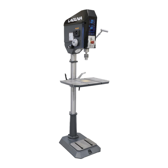
- Page 2 Thank you for investing in a DP20 Drill Press by Laguna Tools. This drill press is one of a family of unique machines proudly offered by Laguna Tools. Every Laguna machine is engineered for years of dependable service. Please feel free to contact Laguna Tools if you have a question or suggestion.
-
Page 3: Table Of Contents
CONTENTS Warranty Safety *Electrical Video & Information Specifications Main Components & Controls Inventory Unpacking & Assembly Electrical Connections Control Panel Programming RPM Selection/Drill Speed Depth Stop Laser Light Using the Drill Press Maintenance Trouble Shooting Wiring Diagram Exploded Views Parts List Accessories... -
Page 5: Receiving Your Machine
Receiving your machine It is probable that your machine will be delivered by a third party. Before you unpack your new machine, you will need to first inspect the packing, invoice and shipping documents supplied by the driver. Ensure that there is no visible damage to the packaging or the machine. You need to do this prior to the driver leaving. - Page 6 Laguna English French For your own safety, read instruction manual Pour votre securite, lisez le manuel WARNING: AVERTISSEMENT: before operating bandsaw d'instruction attentivement avant d'utiliser la scie ruban. Wear eye protection. Portez des lunettes de protection Do not remove jammed cut off pieces until blade Ne tentez pas d'enlever une piece coincee avant has stopped.
- Page 7 SECURE WORK. Use clamps or a vise to hold work 10. PORTEZ DES VETEMENTS APPROPRIES. Ne portez when practical. It is safer than using your hand, and pas de vetements ampies, des gants, des colliers, it frees both hands to operate tool. des bracelets, ou tout autre bijou ou accessoire qui DON'T OVERREAC always Keep proper...
- Page 8 remplace. 20. SENS D'ALIMENTATION. Alimentez la piece vers la lame ou le couteau dans le sens contraire de sa rotation seulement. NE LAISSEZ JAMAIS UN OUTIL FONCTIONNER DANS SURVEILLANCE - ETEIGNEZ L'OUTIL. Ne laissez pas l'outil sans surveillance jusqu'a ce qu'il s'arrete completement.
-
Page 9: Electrical
Table A Ampere Rating Volts Total length of cord in feet More Than Not More Than Minimum gage for cord Not Recommended GROUNDING INSTRUCTIONS 1. All grounded, cord-connected tools: In the event of a malfunction or breakdown, grounding provides a path of least resistance for electric current to reduce the risk of electric shock. -
Page 10: Video & Information
Below is a link and QR code to a DP20 video showing features and operation information. It is a great way to familiarize the unique features and capabilities of this new era of drill press offerings from Laguna Tools. Copy the URL or scan the QR code. www.lagunatools.com/classic/drill-presses/dp20/... -
Page 11: Specifications
Specifications MDP20-1 Motor voltage/hp 115V / 1.5 HP Breaker 15 amp. min. 72” (1830mm) Power cord 15” x 22” Table, cast iron (380mm x 560mm) Table tilt +/- 90 degrees Table swivel 360 degrees Laser light Included Working light LED, 5W 20”... - Page 12 Drill Press Introduction This drill press is designed to give you years of safe service. Read this owner’s manual in its entirety before assembly or use. The drill press does not have many parts. The major parts are discussed in this manual. If you are not familiar with the drill press, take the time to read this section and become familiar with the machine.
- Page 13 • E-STOP An emergency STOP button (red) is located on the front of the headstock. Depress the red knob to stop the machine. Twist the red button to reset and turn power back on. Only reset this button after the emergency has been corrected. Figure 4: Emergency-STOP (Twist to reset) •...
- Page 14 Identification/Serial label: There is a plate at the back of the machine (below the main power switch) listing the manufacturing data, including the serial number and model. Figure 6: Identification Label Motor (Not Shown): The drill press is supplied with a 1-1/2 hp, 110V motor. The motor drives the quill and Chuck through a pulley system.
-
Page 15: Main Components & Controls
Main Components & Controls of the Drill Press Figures 7 & 8: Components A. Key, chuck J. Touch Screen Controls, PLC B. Quill Control, Left K. Handle, Arbor Depth Control, Right C. Laser, Left ½ L. RPM & Programming Control D. -
Page 16: Inventory
Where to locate your Drill Press Before you remove your drill press from the packaging, select the area where you will use your . machine. There are no hard-and-fast rules for its location, but below are a few guidelines. 1. There should be an area at the front, back and sides of the machine suitable for the length of material that you will be processing. -
Page 17: Unpacking & Assembly
Unpacking & Assembly Unpacking requires; tin snips, knife, and wrench. Assembly requires; Hex Wrenches Note: The machine is heavy, and if you have any doubt about the described procedure, seek professional assistance. Do not attempt any procedure that you feel is unsafe or that you do not have the physical capability of achieving. - Page 18 2. Cut the box down at the four corners to make the box flat. Cut the end of the bottom, foam insert to access the bottom of the drill press column. 3. Install the machine base, parallel to the head stock, by bolting the base onto the machine column using four 3/8 x 1-1/2”...
- Page 19 6. Remove plastic coverings and clean the anti-rust coatings from the raw cast iron surfaces, using a degreaser such as Simple Green or similar. * Do not use gasoline or distillates on or near painted surfaces, which can harm paint! Figure 17: Removing plastic Figure 18: Cleaning 7.
- Page 20 Figures 20-22: Installing handle (right or left side) 9. Assemble and install the table height adjustment handle, using the 3/8 x 4-1/2” hex bolt, pivot handle and set screw. Figures 23-26: Crank assembly 10.Chuck Installation: Unplug the machine prior to installing the chuck. Clean the tapered portions of the chuck arbor with mineral spirits and a soft rag to ensure that all oil, grease, or other packing debris are cleaned from the arbor.
- Page 21 Clean the internal taper in the drill press with mineral spirits and a soft rag. Use a dowel or pencil to push the rag into the taper for cleaning. Any debris or residual grease can cause the chuck arbor to not seat properly. Dispose of rags safely! Rotate the outer ring of the chuck to retract the jaws into the chuck body to prevent damaging the chuck jaws during installation.
- Page 22 Table Adjustments Table Tilt: The tilt or angle of the table can be adjusted by disengaging the Stop Stud, loosening the Tension Nut and tiling the table to the desired angle. Tighten the tension nut to secure the table in desired position. NOTE: Some models may include a Stop Stud for a 90-degree quick reference (not for precise alignment) and may need to be removed for precision settings of table.
- Page 23 Table Height: The height of the Table can be adjusted along the length of the Column. To adjust the Table Height, loosen the Column Lock on the Table Support Casting and turn the height adjustment handle to move the table to the desired height. Tighten the Column Lock to prevent the Table from moving. Column Table Height Lock...
- Page 24 Table Clamping The DP20 table provides several methods for material clamping. Including one side-to-side T- Slot and two front-to-rear T-Slots to use table clamps, fences, jigs, fixtures, or work vises. Figure 34: T-Slot dimensions Ten holes in the table accept various types of clamps with either 5/8 inch or 16 mm posts. Please note that during manufacturing, these holes may get thicker amounts of powder coating material onto the sides of the hole which could prevent some posts from going into the hole.
-
Page 25: Electrical Connections
The drill press is supplied pre-wired with a 110V 3-pin plug. It is recommended that it be connected to a 15-amp (min.) dedicated circuit. Laguna Tools does not recommend connection to GFI/GFCI outlets or circuits. Local codes often require GFI protected outlets in many areas but also often provide exceptions for certain types of applications including connections to industrial machinery or when the outlet is not easily accessible along with other exceptions. - Page 26 CONTROL PANEL: RPM (Speed) Setting Forward/Reverse button Speed, RPM control button Inch/mm button Depth button (Changes from inch to mm) Zero button Auto Start button Program selection button Auto Reverse button Live Depth (actual) readout Sound ON/OFF button (“ON” chimes when buttons Load, motor load readout are pressed) Laser ON/OFF button...
- Page 27 2. If, after cleaning debris on the quill (if any), the Live Depth display reads something other than 0.00, cycle the power off and then back on using the switch at the rear of the drill press or the E-stop switch at the front of the drill press. Once the boot up screen cycles off, simultaneously press the Depth button and the Laser button momentarily and then release.
-
Page 28: Programming
Programming-Control Panel Specific and repeatable applications can be achieved with programming within the Control Panel. For example, tapping can be programmed with a specific RPM, stopping point and then reversing to back a tap out of the newly threaded hole. The DP20 touch screen will illuminate all the lit elements of the screen during start up. - Page 29 Button Functions/Touch Screen Displays: Each of the touch screen buttons has an illuminated “teal/blue” colored indicator bar below the button. When the indicator bar is illuminated, the feature is active, selected, or in the On position. When the indicator bar is off, the feature is not active. 1.
- Page 30 8. Zero Button - Sets the depth display to Zero when at the material surface. Before drilling, lower the bit down to the surface of the material and press the Zero button. This will set the depth display to zero at the top of the material. Once the zero point is set and the drilling begins, the depth display will show negative values when drilling into the material and positive numbers above the material.
- Page 31 13. Increment Indicators - The indicator bar will illuminate under the selected measurement increment, either Inch or Millimeter (mm). The Inch indicator will be illuminated for either Fractional Inches or Decimal Inches. 14. Auto Start Button - Used for repeated hole drilling to automatically start the spindle when pulling down on the quill stroke handle.
- Page 32 MCU or motor driver. Some errors may also indicate open circuits, under or over voltage. These errors should be noted and communicated to a Laguna Tools Customer Service representative who can assist with a complete diagnosis and...
-
Page 33: Rpm Selection/Drill Speed
Selecting RPM / Drill Speed To adjust the drill press RPM, select the “SPEED” setting on the Control Panel. The light bar next to the switch will light up and flash. While the light bar is flashing rotate the Control Knob until the desired RPM is reached. - Page 34 RPM / Drill Speed Chart Figure 43: Speed Chart (RPM selection)
- Page 35 Drill Bits Fence position The selection and use of bits is a very extensive subject, and there have been many books written on the subject. This section of the manual is intended as a general guide only. Selecting a Drill Bit Using the correct bit is important.
-
Page 36: Setting The Depth Stop
Figure 44: Chuck Key Holder 6. When the chuck jaws are holding the bit in place, tighten securely using the key. Making sure the chuck jaws are not touching the flutes of the bit. 7. To remove the bit, loosen the chuck, using the key while holding the bit with a rag, to prevent the bit from dropping out of the chuck. - Page 37 Figure 46: Laser Light indicator Laser Adjustment: The alignment lasers are pre-set at the factory during production. These lasers can go out of alignment during transportation and assembly and should be checked and adjusted if necessary after machine assembly. They should be checked periodically and adjusted as needed during regular maintenance intervals.
- Page 38 Select one of the laser modules to adjust first. Adjust the crosshair adjustment screw on the laser which is toward the rear of the drill press. Adjust this screw as needed to bring the laser line directly over the dimple in the board. Adjust the laser on the other side of the drill press in the same manner until both lasers cross directly over the dimple in the wood.
-
Page 39: Using The Drill Press
Using the drill press Install desired drill bit, tap, or appropriate tooling into chuck. Tighten Chuck with Key, replace key into magnetic holder. Adjust the table (height, swing & angle) and tighten all locks and tension bolts. Turn ON LED light if needed for this application. Position workpiece on table. -
Page 40: Maintenance
Maintenance All tools and machines require regular maintenance, and the drill press is no exception. This section details the general maintenance and care. In general, we recommend that you only use a Teflon-based lubricant. While regular oil attracts dust and dirt, Teflon tends to dry and has fewer tendencies to accumulate dirt and dust on your machine. -
Page 41: Troubleshooting
Troubleshooting Drill Press will not start: 1. Check that the electrical power cord is plugged into the power outlet. 2. Check that the start switch is fully lifted (back of headstock). 3. Check that the yellow safety plug is fully engaged (back of headstock). 4. -
Page 42: Wiring Diagram
DP18 115V wiring diagram DP20 wiring diagram... -
Page 43: Exploded Views
DP20 Head Assembly exploded view... - Page 44 DP20 Table, Base & Column exploded view...
-
Page 45: Parts List
DP20 Parts List Ref No. Part No. Specifications Description Qty. Machine head 272001A Spring Cover Set 272082S Cross Round Head Screw HS519 M5x10 Flat Cross Head Screw S307 3/16" x 1/2" Spring Cover Set 61103S Cover 272059A Hex Socket Head Screw HS223 MHK027 6x6x30... - Page 46 Hex Socket Head Screw HS228 M6 x 10 Lamp Base 272152 Cross Round Head Screw HS519 M5 x 10 LED light base with latch MET2429 Self-Tapping Screws HS803 M3 x 15 Working Lamp MET2222 Drift Key 6168 Drill Chuck 272129 JT3 5/8"...
- Page 47 Cross Round Head Screw HS510 M4x15L Spring Washer HW102 Mini Gear 272041A Fixed base for Mini gear 272023A MBS-VR-002 WXD3-12 C-Retainer Ring HCR07 C-Retainer Ring HCS17 Bearing CA6006ZZ 6006-ZZ 272017 Spindle Taper Sleeve 272016A Bearing Cap 272065 Cross Round Head Screw HS519 M5 x 10 Spindle Pulley...
- Page 48 Switch MET1249-1 110V Self-Tapping Screws HS807 M4 x 15 Top Cover 272035A Label PJNM403136E09 Cross Round Head Screw HS521 M5 x 20 272078 Label PJNM403136E04 Washer 6630 Hex Socket Headless Screw HS431 M8 x 16 Label PJNM403136E07 CSA RH Laser Cover 272096 Cross Round Head Screw HS522...
- Page 49 LH Laser Rack support 272125 140-4 Self-Tapping Screws 140-5 HS801 M3 x 6 140-6 272127 635nm,5mW,5V, Laser tube 272126 140-7 8x26MM Laser tube sleeve 140-8 272098 Cross Round Head Screw 140-9 HS513 M4 x 30 Washer HW002 140-10 Laser base 272120 140-11 Hex Socker Headless Screw...
- Page 50 Hex Socket Headless Screw S630 3/8"x1/2" Worm Shaft 272081 Worm Gear 260017 Worm Shaft 272114 Washer HW055 12x25x2 Grip 272102 M12x50 Bracket Assembly 272111 Bushing 272113 Limit Plate 272109 Cross Round Head Screw MHS502 M3X5 Rivet MHH001 Scale 272117 Working Table 272005 Table Insert 272116...
- Page 51 PJBM403136S01 70x55cm MHI582 220x200cm MHI577 210x130x70mm PJAM403136S02...
- Page 52 Parts (loose) & Part numbers, quick reference Inventory Ref. Description Qty. Part Number Drill Chuck With Key 5/8" (3-16mm) M272129 If you cannot find an Chuck Drift Key M6168 item on this list, Chuck Arbor (MT2/JT3) M272100 carefully check around/inside the Machine Lift Hook M272078 machine and packaging...
-
Page 53: Accessories
Several of the lights are listed below, but a complete listing can be found on our website by following the, below, URL: https://www.shop.lagunatools.com/classic-machinery/machine-lamps-lights/laguna-led-lights LED light, Part # ALEDMACH LED light, Part # ALEDSPINE LED light, Part # ALEDLATHE Laguna Tools 744 Refuge Way, Suite 200 Grand Prairie TX 75050 800-234-1976 www.lagunatools.com... - Page 54 www.lagunatools.com 053024...
Need help?
Do you have a question about the DS20 and is the answer not in the manual?
Questions and answers