Table of Contents
Advertisement
Quick Links
Advertisement
Table of Contents

Related Manuals for Laguna Tools RPM5


Summary of Contents for Laguna Tools RPM5
- Page 1 RAISED PANEL MASTER RPM3 & RPM5 MANUAL LAGUNA TOOLS 2072 Alton Parkway Irvine, California 92606 Ph: 800.234.1976 www.lagunatools.com © 2018, Laguna Tools, Inc. LAGUNA® and the LAGUNA Logo® are the registered trademarks of Laguna Tools, Inc. All rights reserved.
-
Page 3: Table Of Contents
Table of Contents Warranty Noise emission Speci cation sheet Receiving your machine Unpacking your machine Introduction to your machine Where to locate your machine Assembly and setup Maintenance Troubleshooting Exploded view drawings and parts lists Electrical drawing... - Page 4 Safety Rules As with all machinery there are certain hazards involved with the operation and use. Using it with caution will considerably lessen the possibility of personal injury. However, if normal safety precautions are overlooked or ignored, personal injury to the operator may result. If you have any questions relative to the installation and operation, do not use the equipment until you have contacted your supplying distributor.
-
Page 5: Warranty
Machines sold through dealers must be registered with Laguna Tools within 30 days of purchase to be covered by this warranty. Laguna Tools guarantees all new machines and accessories sold to be free of manufacturers’... -
Page 6: Noise Emission
All damage must be noted on the delivery documents and signed by you and the delivery driver. You must then contact the seller [Laguna Tools] as soon as practical. If damage if found after delivery, contact the seller as soon... -
Page 7: Introduction To Your Machine
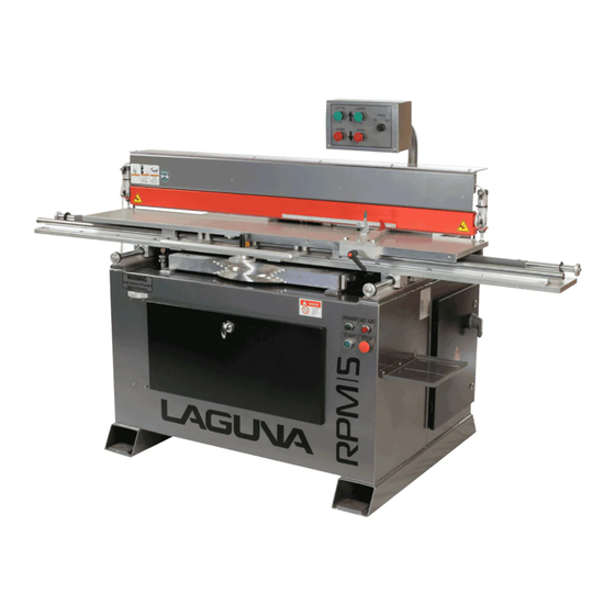
Introduction to Shaper This Shaper is designed to give you years of safe service. Read this owners’ manual in its entirety before assembly or use. PARTS OF THE SHAPER... - Page 8 Electrical connection Sliding table Rear access door Electrical cabinet Power control Turret selector The Machine does not have many parts to assemble. The major parts are discussed in this manual. If you are not familiar with the machine take the time to read this section and become familiar with the machine.
-
Page 9: C A B
1. CABINET The cabinet has a large footprint and is a welded construction manufactured from heavy gauge steel plate. The cabinet houses all the parts of the machine and the heavy construction ensures that the machine is stable. This weight also helps to absorb any vibration that is produced during cutting. -
Page 10: Power Control
7. POWER CONTROL The power control is located on the front of the cabinet and switches the electrical power and air on / o . It is also the location for the start and emergency stop buttons. Power control panel 8. -
Page 11: Fence
12. CONTROL PANEL The control panel moves the cutter up / down and the clamps up / down. It also moves the fence in / out and is situated on an arm over the top of the machine for ease of access. Control panel 13. -
Page 12: Unpacking Your Machine
Where to Locate Your Machine Before you remove your machine from the pallet select the area where you will use your machine. There are no hard and fast rules for its location but below are a few guidelines. 1. Adequate lighting. The better the lighting the more accurate and safely you will be able to work 2. -
Page 13: Assembly And Setup
Assembly and Setup What you will receive with the machine. 1. Tool kit 2. Mounting feet. 3. Leveling bolts. 4. Cabinet keys. 5. Spindle spacers and shims. 6. Spindle wrench. 7. Grease gun CLEANING THE MACHINE Remove the rust protection grease with WD 40 or similar solvent It is important that you remove all the grease and re lubricate with a Te on based lubricant as Te on has less tendency to attract sawdust and cause clogging. - Page 14 bolts so that the table is level in both directions. Ensure that the machine does not rock. ELECTRICAL CONNECTION Note. The machine is not supplied with an electrical plug, as the type of plug will be dependent on the installation. A quali ed electrician must carry out the electrical installation.
- Page 15 CONNECTING AIR TO THE MACHINE The input air regulator regulates the air pressure that is supplied to the machine. You will require an air supply that can deliver a constant minimum pressure of 6.5 bar. The input air regulator will need to be adjusted to 6.5 bar once you have connected your air supply to the machine.
- Page 16 8. Make sure that the guards are in place and use them at all times. The guards protect you from coming in contact with the cutter. 9. Make sure that you use the proper size and type of cutters. Spindle without cutter tted Main electrical isolator 10.
- Page 17 10. With the machine running, slowly open the rear access door until the safety switch cuts the power to the motor. Close the door until the motor has stopped. 11. With the machine running, slowly open the spindle cover until the safety switch cuts the power to the motor.
- Page 18 TEMPLATE FOLLOWER ADJUSTMENT The template follower guides the table [and job] as it is moved along the template. It has a built in height sensor that changes the fence position as it senses that the follower is raised vertically. Note. All straight cuts are made with the follower at the max height. Note.
- Page 19 Stop TURRET HEIGHT ADJUSTMENT Spindle Height Bolts The turret has spindle height adjustment bolts that can be set to suit various heights of cutters. The turret can be removed from the machine to ease adjustment. To remove the turret, raise the spindle so that the stop is o of the spindle height bolts.
- Page 20 TABLE STOPS There are two sets of table stop bolts that limit the rearward movement of the sliding table in relation to the tooling height. The long bolt is for large cutter diameters and the short bolt is for use with small diameter cutters. These stops are preset from the factory and should not require any adjustments.
-
Page 21: Maintenance
Maintenance All tools and machines require regular maintenance and the raised panel master is no exception. This section details the general maintenance and care of your machine. In general we recommend that you only use a Te on based lubricant on the machine. -
Page 22: Troubleshooting
TURRET CHAIN ADJUSTMENT To remove any slack from the turret chain, 1. Loosen the clamp bolt on the chain idler 2. Swivel until the slack is removed. 3. Re-tighten the clamp bolt. Note. Do not over tighten the chain as it will make moving the turret di cult. - Page 23 THE MACHINE WILL NOT STOP This is a very rare occurrence as the machine is designed to fail-safe. If it should occur and you cannot x the fault, seek professional assistance. The machine must be disconnected from the power and never run until the fault has been recti ed. 1.
- Page 24 POOR DUST COLLECTION 1. Check the capacity of the dust collection system. You need a minmum of 1000 cubic feet per minute at the machine. The stronger the dust collection the better. 2. Check the dust hose is not blocked. 3.
-
Page 25: Exploded View Drawings And Parts Lists
Exploded View Drawings and Parts List... -
Page 47: Electrical Drawing
Electrical Drawings... - Page 50 Laguna Tools is not responsible for errors or omissions. Specifications subject to change. Machines may be shown with optional accessories. © 2018, Laguna Tools, Inc. LAGUNA® and the LAGUNA Logo® are the registered trademarks of Laguna Tools, Inc. All rights reserved.
Need help?
Do you have a question about the RPM5 and is the answer not in the manual?
Questions and answers