Table of Contents
Advertisement
Quick Links
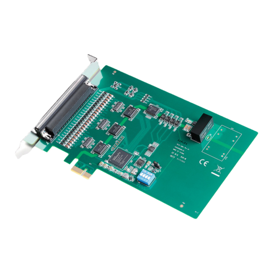
PCIE-1884 32-bit, 4-Ch Encoder Counter PCI Express Card
Startup Manual
Packing List
Before card installation, please ensure that the following
items are included in your shipment:
1. 1 x PCIE-1884 card
2. 1 x Startup manual
If any of these items are missing or damaged, contact your
distributor or sales representative immediately.
User Manual
For more detailed information about this product, refer to
the PCIE-1884 user manual provided on the DVD ROM
(PDF format). DVD:\Documents\Hardware Manuals\PCIE
Declaration of Conformity
FCC Class A
This equipment has been tested and found to comply with
the limits for a Class A digital device, pursuant to part 15
of the FCC Rules. These limits are designed to provide rea-
sonable protection against harmful interference when the
equipment is operated in a commercial environment. This
equipment generates, uses, and can radiate radio frequen-
cy energy and, if not installed and used in accordance with
the instruction manual, may cause harmful interference
to radio communications. Operation of this equipment in
a residential area is likely to cause interference. In such
cases, users are required to correct the interference at their
own expense.
CE
This product has passed the CE test for environmental
specifications when shielded cables are used for external
wiring. We recommend using shielded cables. Such cables
are available from Advantech. Please contact your local
supplier for ordering information.
For more information about this or other Advantech
products, please visit our website at
http://www.advantech.com
For technical support services, please visit our sup-
port website at
http://support.advantech.com
This manual is for PCIE-1884.
Part No. 2041188400
Counter
Channels
Resolution
Filter
Counter
Measurements
Position
Measurements
Output
Applications
Preload FIFO
Size
Isolation
Protection
Base Clock
Output
Frequency
Input Voltage
(Single Ended)
Input Voltage
(Differential)
Counter Output
(Shared with
ID/O)
Error in
Advanced
Functions
Edition 1
October 2018
Specifications
4 channels (independent)
32-bit
1.28 us, 10.24 us, 163.84 us, or 1.31
ms (each channel can be individually
enabled/disabled)
Event counting, frequency measure-
ment, pulse width measurement
Quadrature encoding (X1, X2, and X4;
Channel Z reload), two-pulse encoding,
signed pulse encoding
One shot, timer/pulse, pulse width
modulation, position comparison
1024 values
2500 V
DC
Internal 20 MHz or external clock (10
MHz max.)
Selectable via software
Max. 10 MHz
Low
High
Low
High
Max. Input Voltage ±12 V
Low
High
Frequency
Measurement
Pulse Width
Measurement
Pulse Output
PWM Output
PCIE-1884 Startup Manual 1
0.8 V max.
2.8 V min. (12 V
max.)
"CH+"-"CH-" < -0.5
V max.
"CH+"-"CH-" >
0.5 V min.
0.8 V max.
@+24mA
2.0 V min. @ -24mA
0.1% when input
signal frequency ≥
40 KHz
0.1% when input
signal frequency ≤
40 KHz
within 2% when
output frequency >
1 MHz
within 2% when
output frequency >
1 MHz
Advertisement
Table of Contents

Related Manuals for Advantech PCIE-1884


Summary of Contents for Advantech PCIE-1884
- Page 1 Measurements For more detailed information about this product, refer to Position Quadrature encoding (X1, X2, and X4; the PCIE-1884 user manual provided on the DVD ROM Channel Z reload), two-pulse encoding, Measurements (PDF format). DVD:\Documents\Hardware Manuals\PCIE signed pulse encoding...
-
Page 2: Software Installation
PCIE-1884 card in your computer. 37-pin D-sub female connector Type Please follow the steps below to install the PCIE-1884 card. Dimensions 167.7 x 100 mm (6.6 x 3.9 in) 1. Touch any metal part of your computer to neutralize the +3.3 V @ 290 mA... - Page 3 Isolated digital input channel 0 or sample clock input (general purpose counter) or (encoder counter) of counter channel 0 IDI1/CNT1_SCLK Isolated digital input channel 1 or sample clock input (general purpose counter) or (encoder counter) of counter channel 1 PCIE-1884 Startup Manual 3...
- Page 4 Isolated digital output channel 2 of output of counter channel 2 IDO3/CNT3_OUT Isolated digital output channel 3 of output of counter channel 3 Power and Ground 1, 14, 17, Reference ground for all signals 32, 35 4 PCIE-1884 Startup Manual...
Need help?
Do you have a question about the PCIE-1884 and is the answer not in the manual?
Questions and answers