
Related Manuals for Kontron COMe-cDV7


Summary of Contents for Kontron COMe-cDV7
- Page 1 USER GUIDE COMe-cDV7 Doc. User Guide, Rev 1.0 Doc. ID: 1065-4078 www.kontron.com // 1...
- Page 2 COMe-cDV7 - User Guide, Rev 1.0 This page has been intentionally left blank www.kontron.com // 2...
- Page 3 In cases of doubt, please contact Kontron. This user guide is protected by copyright. All rights are reserved by Kontron. No part of this document may be reproduced, transmitted, transcribed, stored in a retrieval system, or translated into any language or computer language, in any form or by any means (electronic, mechanical, photocopying, recording, or otherwise), without the express written permission of Kontron.
- Page 4 ENVIRONMENTAL DAMAGE (COLLECTIVELY, "HIGH RISK APPLICATIONS"). You understand and agree that your use of Kontron devices as a component in High Risk Applications is entirely at your risk. To minimize the risks associated with your products and applications, you should provide adequate design and operating safeguards.
- Page 5 If you have any difficulties using this user guide, discover an error, or just want to provide some feedback, contact Kontron Support. Detail any errors you find. We will correct the errors or problems as soon as possible and post the revised user guide on our website.
-
Page 6: Symbols
COMe-cDV7 - User Guide, Rev 1.0 Symbols The following symbols may be used in this user guide DANGER indicates a hazardous situation which, if not avoided, will result in death or serious injury. WARNING indicates a hazardous situation which, if not avoided, could result in death or serious injury. -
Page 7: For Your Safety
Therefore, in the interest of your own safety and of the correct operation of your new Kontron product, you are requested to conform with the following guidelines. -
Page 8: Lithium Battery Precautions
General Instructions on Usage In order to maintain Kontron’s product warranty, this product must not be altered or modified in any way. Changes or modifications to the product, that are not explicitly approved by Kontron and described in this user guide or received from Kontron Support as a special handling instruction, will void your warranty. -
Page 9: Table Of Contents
COMe-cDV7 - User Guide, Rev 1.0 Table of Contents Symbols ..........................................6 For Your Safety ........................................7 High Voltage Safety Instructions .................................. 7 Special Handling and Unpacking Instruction ............................7 Lithium Battery Precautions ..................................8 General Instructions on Usage ..................................8 Quality and Environmental Management .............................. - Page 10 Thermal Management ..................................32 5.1. Heatspreader Plate ....................................32 5.2. Active or Passive Cooling Solutions ..............................32 5.3. Operating with Kontron Heatspreader Plate (HSP) Assembly ....................32 5.4. Operating without Kontron Heatspreader Plate (HSP) Assembly ..................32 5.5. Temperature Sensors .................................... 33 5.6.
-
Page 11: List Of Tables
Table 4: Accessories ......................................17 Table 5: Memory Modules ..................................... 17 Table 6: Specification of COMe-cDV7 Processor Variants - Commercial Temperature ............20 Table 7: Specifications of COMe-cDV7 Processor Variants - Industrial Temperature .............. 21 Table 8: Power Supply Control Settings ..............................29 Table 9: Heatspreader Temperature Specifications .......................... -
Page 12: List Of Figures
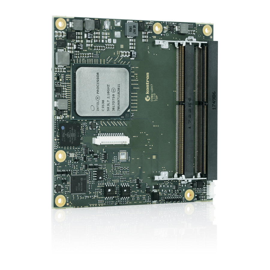
Table 37: Save and Exit Menu Functions ..............................95 Table 37: List of Acronyms ................................... 99 List of Figures Figure 1: COMe-cDV7 COM Express® Module ............................13 Figure 2: Block Diagram COMe-cDV7 ................................. 19 Figure 3: Temperature Sensor Location on the Module ........................33 Figure 4: Fan Connector 3-Pin .................................. -
Page 13: 1/ Introduction
COMe-cDV7 - User Guide, Rev 1.0 1/ Introduction This user guide describes the COMe-cDV7 made by Kontron and focuses on describing the COMe-cDV7’s special features. New users are recommended to study this user guide before switching on the power. 1.1. Product Description The COMe-cDV7 is part of Kontron’s COM Express®... -
Page 14: Product Naming Clarification
1.2. Product Naming Clarification COM Express® defines a Computer-on-Module (COM), with all the components necessary for a bootable host computer, packaged as a super component. The product names for Kontron COM Express® Computer-on-Modules consist of: Industry standard short form ... -
Page 15: Com Express® Functionality
1.4. COM Express® Functionality All Kontron COM Express® basic and compact modules contain two 220-pin connectors. Each connector has two rows called Row A & B on the primary connector and Row C & D on the secondary connector. COM Express® Computer-on- Modules feature the following maximum amount of interfaces according to the PICMG module pinout type. -
Page 16: 2/ Product Specification
COMe-cDV7 - User Guide, Rev 1.0 2/ Product Specification 2.1. Module Variants The COMe-cDV7 is available in different processor, chipset and temperature variants to cover demands in performance, price and power. 2.2. Commercial Grade Modules (0°C to +60°C) Table 2: Product Number for Commercial Grade Modules (0°C to +60°C... -
Page 17: Accessories
COMe-cDV7 - User Guide, Rev 1.0 2.4. Accessories Accessories are either product specific, COMe-type 7 specific or general COMe accessories. For more information contact your local Kontron sales representative or Kontron Inside Sales. Table 4: Accessories Part Number Product Name... - Page 18 COMe-cDV7 - User Guide, Rev 1.0 Part Number Memory (Non ECC) Description 97018-3200-24-0 DDR4-2400 SODIMM 32GB ECC_COM DDR4-2400, 32GB, ECC, 260P, 1200MHz, PC4- 2400 SODIMM 97018-4096-24-2 DDR4-2400 SODIMM 4 GB ECC E2_COM DDR4-2400, 4 GB, ECC, E2, 260P, 1200 MHz, PC4-...
-
Page 19: 3/ Functional Specification
COMe-cDV7 - User Guide, Rev 1.0 3/ Functional Specification 3.1. Block Diagram Figure 2: Block Diagram COMe-cDV7 www.kontron.com // 19... -
Page 20: Processor
Intel® AES New Instructions (AES-NI) Execute Disable Bit Quick Assist Technology The following table lists the specification of the processor variants. The COMe-cDV7’s functional specification deviates from the processor specification. Table 6: Specification of COMe-cDV7 Processor Variants - Commercial Temperature Intel® Atom®... -
Page 21: Table 7: Specifications Of Come-Cdv7 Processor Variants - Industrial Temperature
Decompression The COMe-cDV7 supports a max. of 64 GB with 2x SODIMM sockets /respect. 32 GB with 2-SODIMM sockets High Speed IO (HSIO) lanes shared between PCIe, USB3.0, SATA. Depending on the number of supported HSIO lanes, a max of 14x PCIe lanes, 3x USB3.0 ports and 2x SATA ports are supported... -
Page 22: System On A Chip (Soc)
For volume production, if required, test and qualify other types of RAM. In order to qualify RAM Kontron recommends configuring three systems running a RAM Stress Test program in a heat chamber at 60°C, for a minimum of 24 hours. -
Page 23: Usb 3.0
3.5.2. USB 2.0 The standard USB 2.0 configuration is four USB 2.0 ports with an option for three USB 2.0 ports if Kontron’s Security chip solution (WIBU) is assembled on USB 2.0 port 3. A maximum of eight USB 2.0 ports are supportable when all available USB 3.0 ports are implemented as USB 2.0. -
Page 24: Pci Express (Pcie) Configuration
COMe-cDV7 - User Guide, Rev 1.0 3.7. PCI Express (PCIE) Configuration Up to 14-HSIO PCIe Gen 3 lanes can be routed directly to the COMe connector. The number of available PCIe lanes depends on the C3000 processor variant. The PCIe lanes are configurable in the BIOS setup with x1, x2, x4 and x8 configuration options. -
Page 25: Quad Ethernet Ports (Up To 10 Gb)
COMe-cDV7 - User Guide, Rev 1.0 Additionally, the Intel® I210IT Ethernet controller manages the use of: NC-SI SMBus MCTP over PCIE/SMBUS to enable reporting and control of information exposed to LOM device via the NC-SI The following table lists supported Intel® i210IT Ethernet controller features. -
Page 26: Soc High-Speed Interfaces Overview
COMe-cDV7 - User Guide, Rev 1.0 Jumbo Frames Up to 15.5 KB in basic mode 9.5 KB if virtualization or OS2BMC is enabled VLAN Support 802.1q VLAN Double VLAN Flow Control Support Send/receive pause frames and receive FIFO thresholds Statistics for Management and RMON... -
Page 27: Storage
Speed configurable, default 100 k SMB System time and date ( 3V max. and 10µA if modules not powered) 3.13. Special Features The following table lists the supported Kontron specific product features. External I2C Bus Fast I2C, Multimaster capable Embedded API KEAPI 3.0... -
Page 28: 4/ Power Specification
4.1. Power Supply Specifications The COMe-cDV7 uses either an ATX PSU (12 V) or single power wide range PSU (8.5 V to 20 V). Other supported voltages are 5 V standby and 3.3 V RTC battery input. The COMe-cDV7 supports operation in both single power supply mode and ATX power supply mode. -
Page 29: Power Supply Inrush Current
SFX Design Guide. 4.2. Power Management Power management options are available within the BIOS setup. The COMe-cDV7 implements the Advanced Configuration and Power Interface (ACPI) power states to control typical features such as power button and suspend states. -
Page 30: Power Supply Modes
COMe-cDV7 - User Guide, Rev 1.0 SM-Bus Alert With an external battery manager present and SMB_ALERT #connected, the module (SMB_ALERT#) always powers on even if the BIOS switch “After Power Fail” is set to “Stay Off”. Battery low BATLOW# can be used as a power fail indication in a Type 7 system where assertion prevents wake from S3-S5 states. - Page 31 COMe-cDV7 - User Guide, Rev 1.0 The following table lists the single supply mode settings. State PWRBTN# PWR_OK V5_StdBy / 0 V / 0 V / 0 V G3 → S0 high open / high open connecting VCC high open / high open S5 →...
-
Page 32: 5/ Thermal Management
COM Express® application and environmental conditions. Active or passive cooling solutions for the COMe-cDV7 are usually designed to cover the power and thermal dissipation for a commercial temperature range used in housing with suitable airflow. For more information concerning possible cooling solutions, see Chapter 2.4 Accessories. -
Page 33: Temperature Sensors
COMe-cDV7 - User Guide, Rev 1.0 5.5. Temperature Sensors The thermal resistor (Figure 3, pos.2) placed very close to the SoC measures the SoC temperature, referred to as CPU temperature in the BIOS setup menu (Advanced>H/W Monitor). The thermal resistor is not capable of measuring very fast rises and falls in temperature and measurements may show a certain non-linearity. -
Page 34: On-Board Fan Connector
150 mA if the input voltage is 13 V but less than 20 V. To connect a standard 3-pin connector fan to the module, use one of the adaptor cables listed in the COMe-cDV7 accessories, see Table 10: Fan Connector (3-Pin) Pin Assignment. -
Page 35: 6/ Environmental Specification
COMe-cDV7 - User Guide, Rev 1.0 6/ Environmental Specification 6.1. Temperature Kontron defines operating and non-operating temperature grades for the COMe-cDV7. For more temperature grade information, see Chapter 2.1: Module Variants. Table 12: Temperature Grade Specifications Temperature Grades Operating Non-operating / Storage Commercial Grade 0°C to +60°C... -
Page 36: 7/ Standards And Certification
COMe-cDV7 - User Guide, Rev 1.0 7/ Standards and Certification The COMe-cDV7 plans to comply with the following standards and certificates. If modified, the prerequisites for specific approvals may no longer apply. For more information, contact Kontron Support. Table 14: Standards and Certification Compliance... -
Page 37: Mtbf
(such as extreme altitude, vibration, salt-water exposure) lower MTBF values. Table 15: MTBF MTBF System MTBF (hour) = 606866 h @ 40°C for COMe-cDV7 C3958 10K 2G Reliability report article number: 66002-0000-58-9 The MTBF estimated value above assumes no fan, but a passive heat sinking arrangement. -
Page 38: 8/ Mechanical Specification
COMe-cDV7 - User Guide, Rev 1.0 8/ Mechanical Specification The COMe-cDV7 is compliant with the mechanical specification of the COM Express® PICMG COM.0 Rev 2.1. For CAD drawings, refer to Kontron’s EMD Customer Section. 8.1. Dimensions The dimensions of the compact module are 95 mm x 95 mm (3.74” x 3.74”). -
Page 39: Module Height
COMe-cDV7 - User Guide, Rev 1.0 8.2. Module Height The height of the module depends on the height of the implemented cooling solution. The height of the cooling solution is not specified in the COMe specification. The COM Express® specification defines a module height of approximately 13 mm from module PCB bottom to heatspreader top, as shown in the Figure 7: Module and Carrier Height. -
Page 40: 9/ Features And Interfaces
Kontron’s Security Solution is a security chip for Kontron’s security stack (APPROTECT). The security solution combines a software framework with an integrated security chip connected to the COMe-cDV7’s USB 2.0 port 3 and an additional TPM 2.0 (Trusted Platform Module) chip to provide comprehensive protection for the application software. Kontron APPROTECT encrypts an application's source code in a way that makes reverse engineering impossible (IP Protection/ Reverse Engineering Protection). -
Page 41: Emmc Flash Memory
The Embedded Multimedia Flash Card (eMMC) is eMMC 5.0 compatible and can be permanently attached to the module, allowing for a capacity of up to 64 GByte NAND Flash. During the COMe-cDV7’s manufacturing process, Multi Level Cell (MLC) eMMC is reconfigured to act as pseudo Single Level Cell (pSLC) eMMC, to provide improved reliability, endurance and performance. -
Page 42: Lpc
This leads to limitations for ISA bus and SIO (standard I/Os such as floppy or LPT interfaces) implementation. The COMe-cDV7 LPC clock buffer allows for the connection of three LPC devices All Kontron COM Express® Computer-on-Modules include BIOS support for the following external carrier board LPC Super I/O controller features for the HWM chip Nuvoton NCT7802Y. -
Page 43: Serial Peripheral Interface (Spi)
9.10.1. SPI boot The COMe-cDV7 module supports boot from a 16 MB 3V serial external SPI Flash. To configure the SPI Flash for booting, placing jumpers on pin A34 (BIOS_DIS0#) and pin B88 (BIOS_DIS1#) as follows:... -
Page 44: Module Spi Flash Chips
Depending on the state of the external SPI flash, the program may display up to two warning messages printed in red. Do not stop the process at this point! After a few seconds of timeout, flashing proceeds. For more information, refer to Kontron’s EMD Customer Section. 9.10.4. External SPI flash on Modules with Intel® ME If booting from the external (carrier board mounted) SPI flash then exchanging the COM Express®... -
Page 45: Smbus
System Management Bus (SMBus) is a 2-wire serial interface used to connect several devices. The SMBus’s low bandwidth makes the SMBus ideal for sensors and power related signals with low data content. The COMe-CDV7’s FPGA supports SMB_CK, SMB_DAT and SMB_ALERT# signals. -
Page 46: Virtualization Technology (Intel ® Vt)
The WDT signal is configurable to either of the two stages. After reset, the signal is automatically deasserted. If deassertion is necessary during runtime, contact Kontron Support for further help. -
Page 47: Extended Debug Port Xdp (Option)
COMe-cDV7 - User Guide, Rev 1.0 9.17. eXtended Debug Port XDP (Option) The eXtended Debug Port (XDP) enables user to perform hardware debugging on the system using a 60-pin connector. The XDP interface includes a probe adjacent to the XDP connector and connected to the XDP connector via a ribbon cable. -
Page 48: 10/ System Resources
COMe-cDV7 - User Guide, Rev 1.0 System Resources 10.1. Legacy Interrupt Request (IRQ) Lines The following table specifies the device connected to each Interrupt line or if the line is available for new devices. Table 21: Legacy IRQ Lines General Usage... -
Page 49: I/O Address Map
COMe-cDV7 - User Guide, Rev 1.0 Address Range (hex) Size Project Usage FEB0-0000 FEBF-FFFF Abort FEC0-0000 FEC0-0040 I/O(X)APIC FED0-0000 FED0-03FF High performance event timer FED4-0000 FED4-0FFF TPM- TPM1.2 range FED6-0000 FED6-0FFF XHCI DbC - no other MMIO must overlap this address range... - Page 50 COMe-cDV7 - User Guide, Rev 1.0 I/O Address Range General Usage Project Usage (hex) 03C-03D Interrupt Timer (8252 Timer) Timer/Counter 042-043 04E-04F LPC Controller LPC Controller Interrupt Timer (8252 Timer) Timer/Counter 052-053 PS2 Legacy Keyboard/ Mouse PS2 Legacy Keyboard/ Mouse...
-
Page 51: Pci Devices
COMe-cDV7 - User Guide, Rev 1.0 I/O Address Range General Usage Project Usage (hex) 338-33F 370-375 377-37F 3B0-3B8 Can be routed to PCIe bridge whem Can be routed to PCIe bridge whem BCTL.VGAE ser(fabric) BCTL.VGAE ser(fabric) 3BC-3BE 3C0-3DF Routed to PCIe bridge (fabric) -
Page 52: System Management (Smbus)
COMe-cDV7 - User Guide, Rev 1.0 10.6. System Management (SMBus) The 8-bit SMBus address uses the LSB (bit 0) for the direction of the device. Bit0 = 0 defines the write address Bit0 = 1 defines the read address The following table specifies the 8-bit SMBus write address for all devices and the 7-bit SMBus address without bit 0. -
Page 53: 11/ Come Interface Connector
COMe-cDV7 - User Guide, Rev 1.0 11/ COMe Interface Connector The Come interface connectors (X1A and X1B) on the bottom side of the module contain two 220-pins. Each COMe interface connector contains two rows, named row A & row B on the primary connector (X1A) and rows C & row D on the secondary connector (X1B). -
Page 54: Connecting The Come Interface Connector To The Carrier Board
COMe Rev 2.1 Type 7 standard, contain additional information. The information provided under type, module terminations and comments is complimentary to the COM.0 Rev 3.0 Type 7 standard. For more information, contact Kontron Support. Table 26: General Signal Description... -
Page 55: Come Connector (X1A And X1B) Pin Assignment
COMe-cDV7 - User Guide, Rev 1.0 11.3. COMe Connector (X1A and X1B) Pin Assignment The following tables list the pin assignment of the two 220-pin connectors and both rows. Table 27: X1A Connector Pin Assignment Row (A1-A110) Table 28: X1A Connector Pin Assignment Row (B1-B110) ... - Page 56 COMe-cDV7 - User Guide, Rev 1.0 COMe Signal Description Type Termination Comment Power Ground PWR GND PCIE_TX12+ PCI Express Lane 12 Transmit + DP-O AC Coupled on Module PCIE_TX12- PCI Express Lane 12 Transmit - Power Ground PWR GND USB2- USB 2.0 Data Pair Port 2 –...
- Page 57 COMe-cDV7 - User Guide, Rev 1.0 COMe Signal Description Type Termination Comment NCSI_TX_EN NC-SI Transmit enable I-3.3 (S5) PD 10k GPI3 General Purpose Input 3 I-3.3 PU 100k 3.3V (S0) RSVD Reserved for future use RSVD Reserved for future use...
-
Page 58: Connector X1A Row B1 - B100
COMe-cDV7 - User Guide, Rev 1.0 11.3.2. Connector X1A Row B1 - B100 Table 28: X1A Connector Pin Assignment Row (B1-B110) COMe Signal Description Type Termination Comment Power Ground PWR GND GBE0_ACT# Ethernet Activity LED LPC Frame Indicator O-3.3 LPC_FRAME#/ESPI_C LPC_AD0/ESPI_IO_0 LPC Multiplexed Command, Address &... - Page 59 COMe-cDV7 - User Guide, Rev 1.0 COMe Signal Description Type Termination Comment USB1+ USB 2.0 Data Pair Port 1 + ESPI_EN# LPC/eSPI mode selection PU 20k 3.3V (S5) Not supported USB0_HOST_PRSNT USB host presence on USB0 Not supported SYS_RESET# Reset Button Input I-3.3...
- Page 60 COMe-cDV7 - User Guide, Rev 1.0 COMe Signal Description Type Termination Comment SPI_CS# SPI Chip Select O-3.3 NCSI_ARB_IN NC-SI hardware arbitration input I-3.3 PU 10k (S5) NCSI_ARB_OUT NC-SI hardware arbitration output O-3.3 B100 Power Ground PWR GND B101 FAN_PWMOUT Fan PWM Output O-3.3...
-
Page 61: Connector X1B Row C1 - C110
COMe-cDV7 - User Guide, Rev 1.0 11.3.3. Connector X1B Row C1 - C110 Table 29: X1B Connector Pin Assignment Row (C1-C110) COMe Signal Description Type Termination Comment Power Ground PWR GND Power Ground USB_SSRX0- USB Super Speed Receive – (0) - Page 62 COMe-cDV7 - User Guide, Rev 1.0 COMe Signal Description Type Termination Comment Power Ground PWR GND 10G_PHY_MDC_SCL1 Management I2C Clock for external PHY O/OD-3.3 PU 2k2 3.3V (S5) 10G_PHY_MDC_SCL0 Management I2C Clock for external PHY 10G_INT0 Interrupt From copper PHY or optical SFP I-3.3...
- Page 63 COMe-cDV7 - User Guide, Rev 1.0 COMe Signal Description Type Termination Comment PCIE_RX29- PCI Express Lane 29 Receive - Power Ground PWR GND RSVD Reserved for future use PCIE_RX30+ PCI Express Lane 30 Receive + DP-I PCIE_RX30- PCI Express Lane 30 Receive -...
-
Page 64: Connector X1B Row D1 - D110
COMe-cDV7 - User Guide, Rev 1.0 11.3.4. Connector X1B Row D1 - D110 Table 30: X1B Connector Pin Assignment Row (D1-D110) COMe Signal Description Type Termination Comment Power Ground PWR GND Power Ground USB_SSTX0- USB Super Speed Transmit – (0) - Page 65 COMe-cDV7 - User Guide, Rev 1.0 COMe Signal Description Type Termination Comment Power Ground PWR GND 10G_PHY_MDIO_SDA1 Management I2C Data for external PHY I/O-3.3 PU 2k2 3.3V (S5) 10G_PHY_MDIO_SDA0 Management I2C Data for external PHY I/O-3.3 PU 2k2 3.3V (S5) 10G_INT1 I-3.3...
- Page 66 COMe-cDV7 - User Guide, Rev 1.0 COMe Signal Description Type Termination Comment Power Ground PWR GND PCIE_TX29+ PCI Express Lane 29 Transmit + DP-O AC Coupled on Module PCIE_TX29- PCI Express Lane 29 Transmit - Power Ground PWR GND RSVD...
-
Page 67: 12/ Uefi Bios
12.2. Navigating the uEFI BIOS The COMe-cDV7 uEFI BIOS setup program uses a hot key navigation system. The hot key legend bar is located at the bottom of the setup screens. The following table provides a list of navigation hot keys available in the legend bar. -
Page 68: Getting Help
The right frame displays a help window. The help window provides an explanation of the respective function. 12.4. Setup Menus The Setup utility features a selection bar at the top of the screen that lists the menus. Figure 11: Setup Menu Selection Bar The Setup menus available for the COMe-cDV7 are: Main ... -
Page 69: Main Menu
The following table shows Main sub-screens and functions, and describes the content. Table 32: Main Setup Menu Functions Sub-Screen Description BIOS Read only field Information BIOS Vendor, Core Version, Compliancy, Kontron BIOS version, Access Level Memory Read only field Information Total memory Platform Read only field... -
Page 70: Advanced Menu
COMe-cDV7 - User Guide, Rev 1.0 12.4.2. Advanced Menu The Advanced setup menu provides sub-screens and second level sub-screens with functions, for advanced configuration and Kontron specific configurations. Setting items, on this screen, to incorrect values may cause system malfunctions. - Page 71 COMe-cDV7 - User Guide, Rev 1.0 Sub-Screen Second Level Further Sub-Screens/Description Sub-screen ACPI Settings Lock Legacy Lock of legacy resources (continued) Resources [Enabled, Disabled] Miscellaneous Watchdog Auto Reload Automatic reload of watchdog timers on timeout [Enabled, Disabled] Global Lock Enable sets all Watchdog registers (except for WD_KICK) to read only, until board is reset.
- Page 72 COMe-cDV7 - User Guide, Rev 1.0 Sub-Screen Second Level Further Sub-Screens/Description Sub-screen H/W Monitor Ref. Temperature source for automatic fan control (continued) Temperature [Module Temperature, CPU Temperature] External Fan – showing current RPM Fan Control Sets fan control mode Note: Disable - stops fan...
- Page 73 COMe-cDV7 - User Guide, Rev 1.0 Sub-Screen Second Level Further Sub-Screens/Description Sub-screen Read only field Configuration AMI SIO Driver Version Super IO Chip Logical Device(s) Configuration Serial Port 1 Use This Device Enable or disable this logical device. [Enabled, Disabled]...
- Page 74 COMe-cDV7 - User Guide, Rev 1.0 Sub-Screen Second Level Further Sub-Screens/Description Sub-screen Floppy disk Use This Device Enable or disable this logical device. Configuration Controller [Enabled, Disabled] (continued) Configuration Logical Device Settings: Current Read only field To refresh- reset required Possible Change device’s resource settings.
- Page 75 COMe-cDV7 - User Guide, Rev 1.0 Sub-Screen Second Level Further Sub-Screens/Description Sub-screen PCI Express PCI Subsystem PCI Express Link Register Settings Settings Settings ASPM Support Sets ASPM level, where Auto selects BIOS auto conf. (continued) (continued) [Auto, Disabled] Warning Enabling ASPM may cause some PCI-E devices to fail.
- Page 76 COMe-cDV7 - User Guide, Rev 1.0 Sub-Screen Second Level Further Sub-Screens/Description Sub-screen PCI Subsystem PCI Express GEN Clock Power Permitted to use CLKREQ# signal for power management Settings 2 Settings Management of link clock in accordance to protocol. (continued) [Enabled, Disabled]...
- Page 77 COMe-cDV7 - User Guide, Rev 1.0 Sub-Screen Second Level Further Sub-Screens/Description Sub-screen Device Reset Timeout value of USB mass storage device start unit command time-out Configuration Time-out [20 sec] (continued) Device Power-up Max. time for device to report to host controller. Auto uses root port default Delay value 100 ms, for hub port delay is taken.
-
Page 78: Interlrcsetup Menu
COMe-cDV7 - User Guide, Rev 1.0 12.4.3. InterlRCSetup Menu The IntelRCsetup Setup menu provides sub-screens and second level sub-screens for processor related functions. Figure 14: IntelRCSetup Menu Screen The following table shows the InterlRCSetup menu sub-screens and functions, and describes the content. Default settings are in bold. - Page 79 COMe-cDV7 - User Guide, Rev 1.0 Function Second level Sub-Screen / Description Fia Mux Lane [0 to 19] Lanes can be set to PCIE, XHCI , SATA or Lane Disabled Configuration [lane Disabled] (continued) Additional Information: The HSIO lanes [0-19] support the following:...
- Page 80 COMe-cDV7 - User Guide, Rev 1.0 Function Second level Sub-Screen / Description Processor Fast String Enables fast string for REP MOVS/STOS Configuration [Enabled, Disabled] (continued) Machine Check [Enabled, Disabled] Max COUID Value Enable to boot legacy OSs that cannot support CPUs with extended CPUID...
- Page 81 COMe-cDV7 - User Guide, Rev 1.0 Function Second level Sub-Screen / Description CPU Thermal CPU DFX Thermal High Temp Interrupt Triggers input when temperature goes from Configuration Configuration NOT_HOT to HOT (continued) (continued) [Enabled, Disabled] Threshold 1 Rel Temp Degrees below TJMax to signal an interrupt whenever temperature crosses this threshold.
- Page 82 COMe-cDV7 - User Guide, Rev 1.0 Function Second level Sub-Screen / Description Miscellaneous Inspectrum Required to test PCIe CLB Configuration [Enabled, Disabled] (continued) Enable Modphy for [SATA DTLE=7, SATA3 DTLE=3, Disabled] I/O Compliance Wake on LAN Wake on LAN Configuration setting...
- Page 83 COMe-cDV7 - User Guide, Rev 1.0 Function Second level Sub-Screen / Description Server ME debug NM Configuration DRAM Init Done Waiting for DRAM initialization notify Configuration (continued) Time acknowledge from ME with 5 sec timeout (continued) [Enabled, Disabled] DRAM Initialization...
- Page 84 COMe-cDV7 - User Guide, Rev 1.0 Function Second level Sub-Screen / Description System Event Memory Event log Log Correctable [Enabled, Disabled] (continued) Error (continued) Log Un-correctable [Enabled, Disabled] Error Enable /Disable Error clocking feature to hide CE errors to OS...
- Page 85 COMe-cDV7 - User Guide, Rev 1.0 Function Second level Sub-Screen / Description North Bridge Pass Gate Setup Pass Gate Test Swizzle Forces Sizzle mode (Samsung) Chipset (continued) [Auto, Enabled] Configuration Pass Gate Test pattern [0’s] (continued) Pass Gate Test Target Pattern [1’s]...
- Page 86 COMe-cDV7 - User Guide, Rev 1.0 Function Second level Sub-Screen / Description North Bridge Leaky Bucket Setup Rank 0 Chipset (continued) Rank 1 Configuration (continued) Non Volatile Read only data memory Setup SoC Pwr los support, cashe Flushinh, ADR State Source, Internal Pwr Loss...
- Page 87 COMe-cDV7 - User Guide, Rev 1.0 Function Second level Sub-Screen / Description North Bridge E Segments in Reads & write targeting segment E routed to DRAM Chipset DRAM [Enabled, Disabled] Configuration F Segments in Reads & write targeting segment F routed to DRAM...
- Page 88 COMe-cDV7 - User Guide, Rev 1.0 Function Second level Sub-Screen / Description North Bridge High Temperature Temperature in°C.. 105 Chipset Medium Temperature in°C.. 85 Configuration Temperature (continued) Low Temperature Temperature in°C.. 82 Critical BW Level Bandwidth level as % High BW Level...
- Page 89 COMe-cDV7 - User Guide, Rev 1.0 Function Second level Sub-Screen / Description SATA0 Read Only Field South Bridge / SATA1 Device Information and Device Size Chipset Configuration Configuration Enable/Disable Port SATA controller Port (continued) (continued) [Disabled, Enabled] Hot Plug Designates this port as Hot Pluggable.
- Page 90 COMe-cDV7 - User Guide, Rev 1.0 Function Second level Sub-Screen / Description South Bridge PCIE IP Root Port [0 - 7] Clock Gating [Disabled, Enabled] Chipset Configuration (continued) Max. Payload Set max. payload of PCIe Configuration (continued) Root Port or allow BIOS to...
- Page 91 COMe-cDV7 - User Guide, Rev 1.0 Function Second level Sub-Screen / Description South Bridge Root Port [0 - 7] Completion 1 ms to 10 ms, PCIE IP Chipset Timeout 16 ms to 55 ms, (continued) Configuration Configuration Range 65 ms to 210 ms,...
-
Page 92: Security Menu
COMe-cDV7 - User Guide, Rev 1.0 12.4.4. Security Menu The Security setup menu provides information about the passwords and functions for specifying the security settings. Figure 15: Security Setup Menu Screen The following table shows Security sub-screens and functions, and describes the content . - Page 93 It is highly recommended to keep a record of all passwords in a safe place. Forgotten passwords results in the user being locked out of the system. If the system cannot be booted because the User Password or the Supervisor Password are not known, clear the uEFI BIOS settings, or contact Kontron Support for further assistance. www.kontron.com // 93...
-
Page 94: Boot Menu
COMe-cDV7 - User Guide, Rev 1.0 12.4.5. Boot Menu The Boot setup menu lists the dynamically generated boot device priority order and the boot options. Figure 16: Boot Setup Menu Screen The following table shows Boot sub-screens and functions, and describes the content. Default settings are in bold. -
Page 95: Save And Exit
COMe-cDV7 - User Guide, Rev 1.0 12.4.6. Save and Exit The Save and Exit setup menu lists the save, default and override options. Figure 17: Save and Exit Setup Menu Screen The following table shows Boot sub-screens and functions, and describes the content. -
Page 96: Basic Operation Of The Uefi Shell
12.5. The uEFI Shell The Kontron uEFI BIOS features a built-in and enhanced version of the uEFI Shell. For a detailed description of the available standard shell scripting, refer to the EFI Shell User Guide. For a detailed description of the available standard shell commands, refer to the EFI Shell Command Manual. -
Page 97: 13/ Technical Support
The buyer accepts responsibility for all freight charges for the return of goods to Kontron's designated facility. Kontron will pay the return freight charges back to the buyer's location in the event that the equipment is repaired or replaced within the stipulated warranty period. Follow these steps before returning any product to Kontron. -
Page 98: 14/ Warranty
14.1. Limitation/Exemption from Warranty Obligation In general, Kontron shall not be required to honor the warranty, even during the warranty period, and shall be exempted from the statutory accident liability obligations in the event of damage caused to the product due to failure to observe the following: ... -
Page 99: Appendix A: List Of Acronyms
COMe-cDV7 - User Guide, Rev 1.0 Appendix A: List of Acronyms Table 38: List of Acronyms ACPI Advanced Configuration Power General Purpose Input Interface GPIO General Purpose Input Output BIOS Basic Input Output System General Purpose Output Board Support Package... - Page 100 COMe-cDV7 - User Guide, Rev 1.0 PCI Express Graphics Single Level Cell PICMG® SMBus PCI Industrial Computer Manufacturers System Management Bus Group System on a Chip Ethernet controller physical layer SODIMM Small Outline Dual In-line Memory device Module Pin-out COM Express® definitions for signals on...
- Page 101 COMe-cDV7 – User Guide, Rev 1.0 About Kontron Kontron is a global leader in embedded computing technology (ECT). As a part of technology group S&T, Kontron offers a combined portfolio of secure hardware, middleware and services for Internet of Things (IoT) and Industry 4.0 applications. With its standard products and tailor-made solutions based on highly reliable state-of-the-art embedded technologies, Kontron provides secure and innovative applications for a variety of industries.
Need help?
Do you have a question about the COMe-cDV7 and is the answer not in the manual?
Questions and answers