
Related Manuals for Kontron COMe-m4AL10


Summary of Contents for Kontron COMe-m4AL10
- Page 1 USER GUIDE COMe-m4AL10 Doc. User Guide, Rev. 1.1 Doc. ID: 1065-8037 www.kontron.com // 1...
- Page 2 COMe-m4AL10 - User Guide, Rev. 1.1 This page has been intentionally left blank www.kontron.com // 2...
- Page 3 In cases of doubt, please contact Kontron. This user guide is protected by copyright. All rights are reserved by Kontron. No part of this document may be reproduced, transmitted, transcribed, stored in a retrieval system, or translated into any language or computer language, in any form or by any means (electronic, mechanical, photocopying, recording, or otherwise), without the express written permission of Kontron.
- Page 4 ENVIRONMENTAL DAMAGE (COLLECTIVELY, "HIGH RISK APPLICATIONS"). You understand and agree that your use of Kontron devices as a component in High Risk Applications is entirely at your risk. To minimize the risks associated with your products and applications, you should provide adequate design and operating safeguards.
- Page 5 If you have any difficulties using this user guide, discover an error, or just want to provide some feedback, contact Kontron support. Detail any errors you find. We will correct the errors or problems as soon as possible and post the revised user guide on our website.
-
Page 6: Symbols
COMe-m4AL10 - User Guide, Rev. 1.1 Symbols The following symbols may be used in this user guide DANGER indicates a hazardous situation which, if not avoided, will result in death or serious injury. WARNING indicates a hazardous situation which, if not avoided, could result in death or serious injury. -
Page 7: For Your Safety
Therefore, in the interest of your own safety and of the correct operation of your new Kontron product, you are requested to conform with the following guidelines. -
Page 8: Lithium Battery Precautions
General Instructions on Usage In order to maintain Kontron’s product warranty, this product must not be altered or modified in any way. Changes or modifications to the product, that are not explicitly approved by Kontron and described in this user guide or received from Kontron Support as a special handling instruction, will void your warranty. -
Page 9: Table Of Contents
COMe-m4AL10 - User Guide, Rev. 1.1 Table of Contents Symbols ..........................................6 For Your Safety ........................................7 High Voltage Safety Instructions .................................. 7 Special Handling and Unpacking Instruction ............................7 Lithium Battery Precautions ..................................8 General Instructions on Usage ..................................8 Quality and Environmental Management .............................. - Page 10 5.1. Heatspreader Plate (HSP) Assembly and Metal Heat Slug ......................29 5.2. Active/Passive Cooling Solutions ..............................29 5.3. Operating with Kontron Heatspreader Plate (HSP) Assembly ....................29 5.4. Operating without Kontron Heatspreader Plate (HSP) Assembly ..................29 5.5. Temperature Sensors .................................... 30 5.6.
-
Page 11: List Of Tables
About Kontron ........................................81 List of Tables Table 1: Type 10 and COMe-m4AL10 Functionality ..........................15 Table 2: Product Number for Commercial Grade Modules (0°C to +60°C operating) ..............16 Table 3: Product Number for Industrial Grade Modules (-40°C to +85°C operating) ..............16 Table 4: Accessories ...................................... -
Page 12: List Of Figures
Table 38: Save and Exit Setup Menu Sub-screens and Functions ....................73 Table 39: List of Acronyms ................................... 79 List of Figures Figure 1: COMe-m4AL10 Front Side ................................13 Figure 2: Block Diagram COMe-m4AL10 ..............................18 Figure 3: SoC Temperature Sensor ................................30 Figure 4: Module Temperature Sensor .............................. -
Page 13: 1/ Introduction
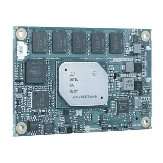
COMe-m4AL10 - User Guide, Rev. 1.1 1/ Introduction This user guide describes the COMe-m4AL10 made by Kontron and focuses on describing the COMe-m4AL10’s special features. New users are recommended to study this user guide before switching on the power. 1.1. Product Description The COMe-m4AL10 is small form factor COM Express®... -
Page 14: Product Naming Clarification
1.2. Product Naming Clarification COM Express® defines a Computer-On-Module (COM), with all the components necessary for a bootable host computer, packaged as a super component. The product name for Kontron COM Express® Computer-On-Modules consists of: Industry standard short form ... -
Page 15: Com Express® Functionality
COMe-m4AL10 - User Guide, Rev. 1.1 1.4. COM Express® Functionality All Kontron COM Express® mini modules contain one 220-pin connector containing two rows called row A & row B. The COM Express® mini Computer-On-Module (COM) features the following maximum amount of interfaces according to the PICMG module pinout type. -
Page 16: 2/ Product Specification
COMe-m4AL10 - User Guide, Rev. 1.1 2/ Product Specification 2.1. Module Variants The COMe-m4AL10 is available in different processor, memory and temperature variants to cover demands in performance, price and power. The following tables list the module variants for the commercial and industrial temperature grades. -
Page 17: Accessories
COMe-m4AL10 - User Guide, Rev. 1.1 2.4. Accessories Accessories are either product specific, COMe-type 10 specific, or general COMe accessories. For more information, contact your local Kontron Sales Representative or Kontron Inside Sales. Table 4: Accessories Part Number Heatspreader Description... -
Page 18: 3/ Functional Specification
COMe-m4AL10 - User Guide, Rev. 1.1 3/ Functional Specification 3.1. Block Diagram Figure 2: Block Diagram COMe-m4AL10 www.kontron.com // 18... -
Page 19: Processors
Intel® HD Audio Technology Intel® Identity Protection Technology Intel® AES New Instructions Secure Key The following table lists the processor specifications compatible with the COMe-m4AL10. Table 5: Specification of COMe-m4AL10 Processor Variants Intel® Atom™ Atom® Atom™ Pentium®... -
Page 20: Platform Controller Hub (Pch)
PCH. 3.4. System Memory The COMe-m4AL10 supports LPDDR4 memory down with up to four (x32) channels, with a capacity of up to 16 GByte. The maximum data transfer rate is 2400 MT/s for industrial and commercial temperature graded variants. -
Page 21: Hd Audio
PCIe lane configuration: Configuration 1 – default setting in BIOS Configuration 2 & 4 – BIOS versions are available in Kontron’s Customer Section Configuration 3 – For information , contact Kontron support 3.9. USB The eight USB ports are configured as six dedicated USB 2.0 ports and two dual USB 3.0/2.0 ports... -
Page 22: Sata
COMe-m4AL10 - User Guide, Rev. 1.1 The COMe USB port 7 is a dual role (Client /Host). When Kontron’s security chip is connected SOC port 7, the COMe USB 2.0 port 6 is not available. The following table shows the COMe connector to SoC High-speed I/O port relationship for USB 3.0/USB 2.0 COMe USB 2.0... -
Page 23: Come High-Speed Serial Interfaces Overview
COMe-m4AL10 - User Guide, Rev. 1.1 Advanced cable diagnostics, auto MDI-X Error correcting memory (ECC) IEEE1588/802.1AS precision time synchronization for Time Sensitive Networking (TSN) applications 3.12. COMe High-speed Serial Interfaces Overview The high-speed serial interfaces PCI Express Gen. 2.0, USB 3.0, SATA Gen.3 and 1 GBE are available on the COM Express®... -
Page 24: Come Specification Features
Dual staged TPM 2.0 Display (DDI) 4K resolutions APPROTECT Security Solution Kontron security chip supported on Soc port 7/COMe USB 2.0 port 6 (optional) 3.17. Optional Features The following table lists the supported optional features. PCIE Up to four external devices... -
Page 25: 4/ Power Specification
4.1. Power Supply Specification The COMe-m4AL10 uses either a wide range power supply (4.75 V to 20 V) or a +12 V single power rail nominal voltage. Other supported voltages are 5 V standby and 3.3 V RTC battery input. The COMe-m4AL10 supports operation in both single power supply mode and ATX power supply mode. -
Page 26: Power Supply Inrush Current
SFX Design Guide. 4.2. Power Management Power management options are available within the BIOS setup. The COMe-m4AL10 implements the Advanced Configuration and Power Interface (ACPI) ACPI 5.0 hardware specification to control typical features such as power button and suspend states. -
Page 27: Power Supply Modes
COMe-m4AL10 - User Guide, Rev. 1.1 After a complete power loss (including battery voltage), there is an additional cold reset. This additional reset will not happen on any subsequent warm or cold reboots. 4.2.2. Power Supply Modes Setting the power supply controls enables the module to operating in either: ... -
Page 28: Table 9: Single Power Supply Mode Settings
COMe-m4AL10 - User Guide, Rev. 1.1 The following table provides the single power supply mode settings. Table 9: Single Power Supply Mode Settings State PWRBTN# PWR_OK V5_Standby 0V/x 0V/x 0V/x 0V/x high open / high open S5 → S0 PWRBTN Event... -
Page 29: 5/ Thermal Management
COM Express® application and environmental conditions. Kontron’s active or passive cooling solutions for the COMe-m4AL10 are usually designed to cover the power and thermal dissipation for a commercial temperature range used in housing with a suitable airflow. For more information concerning possible cooling solutions, see Table 4: Accessories. -
Page 30: Temperature Sensors
COMe-m4AL10 - User Guide, Rev. 1.1 5.5. Temperature Sensors The thermal resistor (Figure 3, pos. 1) placed very close to the SoC measures the SoC temperature. The thermal resistor is not capable of measuring very fast rises and falls in temperature and measurements may show a certain non- linearity. -
Page 31: On-Board Fan Connector
5.6. On-board Fan Connector The module’s fan connector powers, controls and monitors an external fan. To connect a standard 3-pin connector fan to the module, use one of Kontron’s adaptor cables, see Table 4: Accessories. Figure 5: Fan Connector 3-Pin... -
Page 32: 6/ Environmental Specification
COMe-m4AL10 - User Guide, Rev. 1.1 6/ Environmental Specification Kontron defines operating and non-operating temperature grades for the COMe-m4AL10. For more temperature grade information, see Chapter 2.1 Module Variants. Table 13: Temperature Grade Specifications Temperature Grades Operating Non-operating (Storage) Commercial Grade 0°C to +60°C... -
Page 33: 7/ Standards And Certifications
COMe-m4AL10 - User Guide, Rev. 1.1 7/ Standards and Certifications The COMe-m4AL10 complies with the following standards and certificates. If modified, the prerequisites for specific approvals may no longer apply. For more information, contact Kontron Support. Table 15: Standards and Certifications... -
Page 34: Mtbf
(such as extreme altitude, vibration, salt-water exposure) lower MTBF values. Table 16: MTBF MTBF System MTBF (hour) = 796297 h @ 40°C for COMe-m4AL10 E2 E3930 2G Reliability report article number: 34011-0200-13-5 The MTBF estimated value above assumes no fan, but a passive heat sinking arrangement. -
Page 35: 8/ Mechanical Specification
COMe-m4AL10 - User Guide, Rev. 1.1 8/ Mechanical Specification The COMe-m4AL10 is compliant with the mechanical specification of the COM Express® PICMG COM.0 Rev 2.1. 8.1.1. Module Dimensions The dimensions of the mini module are: 84 mm x 55 mm (3.3“x 2.17“) Figure 7: Module Dimensions *All dimensions are in mm. -
Page 36: Heatspreader And Metal Heat Slug Dimensions
COMe-m4AL10 - User Guide, Rev. 1.1 8.1.3. Heatspreader and Metal Heat Slug Dimensions The industrial temperature grade variants include a preconfigured Intel heatspreader and therefore the metal slug, supplied in the delivery, does not have to be installed. The commercial temperature grade variants do not include a preconfigured Intel heatspreader and the metal heat slug supplied in the delivery must be installed. -
Page 37: 9/ Features And Interfaces
Kontron’s Security Solution is a security chip for Kontron’s security stack (APPROTECT). The security solution combines a software framework with an integrated security chip connected to the COMe-m4AL10’s Soc port 7/COMe USB 2 port 6, and an additional (Trusted Platform Module) TPM 2.0 chip to provide comprehensive protection for the application software. -
Page 38: Emmc Flash Memory (Option)
COMe-m4AL10 - User Guide, Rev. 1.1 9.3. eMMC Flash Memory (option) The Embedded Multimedia Flash Card (eMMC) is eMMC 5.0 compatible and supports up to 64 GByte NAND Flash. During the manufacturing process, Multi Level Cell (MLC) eMMC is reconfigured to act as pseudo Single Level Cell (pSLC) eMMC to provide improved reliability, endurance and performance. -
Page 39: Lpc
Advanced setup menu and has no OS software support: Advanced> H/W Monitor> The HWM is accessible via the System Management (SM) Bus, for more information see Chapter 10.6: System Management (SM) Bus. If any other LPC Super I/O additional BIOS implementations are necessary, contact Kontron Support. -
Page 40: Spi Boot
COMe-m4AL10 - User Guide, Rev. 1.1 The SPI Flash chip supports: Dual SPI with 2 data bits per clock cycle Quad SPI with 4 data bits per clock cycle QPI with data and command over 4 data lines 9.9.1. -
Page 41: External Spi Flash Boot On Modules With Intel® Management Engine
COMe-m4AL10 - User Guide, Rev. 1.1 Reboot system into EFI shell. From the EFI shell, enter the name of the partition of the USB Key in this example; select FS0: then press <enter>. Enter the following: FPT –F <biosname.BIN> Wait until the program ends properly and then power cycle the whole system. -
Page 42: Trusted Platform Module (Tpm 2.0)
“kicking the dog”, “petting the dog”, “feeding the watchdog” or “triggering the watchdog”. The COMe-m4AL10 offers a watchdog that works with two stages that can be programmed independently, and used stage by stage. -
Page 43: Watchdog Timer Signal
The WDT signal is configurable to any of the two stages. After reset, the signal is automatically deasserted. If deassertion is necessary during runtime, contact Kontron Support for further help. 9.15. XDP Debug Port (option) The eXtended Debug Port (XDP) enables hardware debugging on the system using an optional 60-pin connector. -
Page 44: System Resources
COMe-m4AL10 - User Guide, Rev. 1.1 System Resources 10.1. Interrupt Request (IRQ) Lines The following table specifies the device connected to each Interrupt line or if the line is available for new devices. Table 23: Interrupt Requests General Usage Project Usage... -
Page 45: I/O Address Map
COMe-m4AL10 - User Guide, Rev. 1.1 10.3. I/O Address Map The I/O port addresses are functionally identical to a standard PC/AT. All addresses not mentioned in this table should be available. We recommend that you do not use I/O addresses below 0100h with additional hardware, for compatibility reasons, even if the I/O address is available. -
Page 46: Peripheral Component Interconnect (Pci) Devices
COMe-m4AL10 - User Guide, Rev. 1.1 I/O Address Range General Usage Project Usage 300-301 MIDI Not used 300-31F System specific peripherals Not used 370-377 Floppy disk controller Not used 376-377 HDD-Controller IDE1 Slave Not used 378-37F Parallel port LPT 1... -
Page 47: Table 27: Smbus Address
COMe-m4AL10 - User Guide, Rev. 1.1 The following table specifies the 8-bit SMBus write address for all devices and the 7-bit SMBus address without bit 0. Table 27: SMBus Address SMBus 8-bit 7-bit Device Description Address Address HWM NCT7802Y Do not use under any circumstances... -
Page 48: 11/ Come Interface Connector
COMe-m4AL10 - User Guide, Rev. 1.1 11/ COMe Interface Connector The COMe Interface connector (X1A) mounted on the bottom side of the module contains 220-pins with two rows (row A and row B), where row A contains pins A 1 to A110 and row B contains B 1 to B110. -
Page 49: Connecting The Come Interface Connector To The Carrier Board
PICMG specification COMe Rev 2.1 Type 10 standard, contain additional information. The information provided under type, module terminations and comments is complimentary to the COM.0 Rev 3.0 Type 10 standard. For more information, contact Kontron Support. Table 28: General Signal Description... -
Page 50: Come Interface Connector (X1A ) Pin Assignment
COMe-m4AL10 - User Guide, Rev. 1.1 11.3. COMe Interface Connector (X1A ) Pin Assignment The following tables list the pin assignment of the 220-pin connector and both rows. Table 29: Connector X1A Row A1 to A110 Pin Assignment ... - Page 51 COMe-m4AL10 - User Guide, Rev. 1.1 COMe Signal Description Type Termination Description BATLOW# Provides a battery-low signal to the I-3.3 PU 10 kΩ, Assertion prevents wake from S3-S5 state module to indicate external battery is 3.3 V (S5) ATA_ACT# Serial ATA activity LED indicator OD-3.3...
- Page 52 COMe-m4AL10 - User Guide, Rev. 1.1 COMe Signal Description Type Termination Description PCIE_TX3+ PCI Express transmit lane 3 DP-O PCIE_TX3- Power Ground PWR GND PCIE_TX2+ PCI Express transmit lane 2 DP-O PCIE_TX2- GPI1 General purpose input 1 I-3.3 PU 20 kΩ, 3.3 V (S0)
- Page 53 COMe-m4AL10 - User Guide, Rev. 1.1 COMe Signal Description Type Termination Description TYPE10# Indicates to Carrier Board that type 10 PD 47 kΩ module is installed SER0_TX Serial port 0 TXD O-3.3 20 V protection circuit implemented on-module, PD on carrier boards...
-
Page 54: Connector X1A Row B1 - B110
COMe-m4AL10 - User Guide, Rev. 1.1 11.5. Connector X1A Row B1 – B110 Table 30: Connector X1A Row B1 to B110 Pin Assignment COMe Signal Description Type Termination Description Power Ground PWR GND GBE0_ACT# Ethernet Controller activity LED indicator LPC_FRAME# Indicates the start of an LPC O-3.3... - Page 55 COMe-m4AL10 - User Guide, Rev. 1.1 COMe Signal Description Type Termination Description SPKR Speaker output provides the PC O-3.3 beep signal and is mainly intended for debugging purposes I2C_CK I2C port clock output O-3.3 PU 2.21 kΩ, 3.3 V (S5)
- Page 56 COMe-m4AL10 - User Guide, Rev. 1.1 COMe Signal Description Type Termination Description PCIE_RX2+ PCI Express receive lane 2 DP-I PCIE_RX2- GPO3 General purpose output 3 O-3.3 PD 20 KΩ PCIE_RX1+ PCI Express receive lane 1 DP-I PCIE_RX1- WAKE0# PCI Express Wake Event, wake up I-3.3...
- Page 57 COMe-m4AL10 - User Guide, Rev. 1.1 COMe Signal Description Type Termination Description DDI0CTRLDATA_AUX- DDIO auxiliary data control signal PD 100 kΩ, 3,3V (S0) B100 Power Ground PWR GND B101 FAN_PWMOUT Fan speed control by PWM O-3.3 20 V protection circuit...
-
Page 58: 12/ Uefi Bios
12.2. Navigating the uEFI BIOS The COMe-m4AL10 uEFI BIOS Setup program uses a hot key navigation system. The hot key legend bar is located at the bottom of the setup screens. The following table provides a list of navigation hot keys available in the legend bar. -
Page 59: Getting Help
COMe-m4AL10 - User Guide, Rev. 1.1 The currently active menu and the currently active uEFI BIOS Setup item are highlighted in white. Use the left and right arrow keys to select the Setup menu. Each Setup menu provides two main frames. The left frame displays all available functions and configurable functions are displayed in blue. -
Page 60: Main Setup Menu
COMe-m4AL10 - User Guide, Rev. 1.1 12.4.1. Main Setup Menu On entering the uEFI BIOS, the Setup program displays the Main Setup menu. This screen lists the Main Setup menu sub- screens and provides basic system information as well as functions for setting the system language, time and date. -
Page 61: Advanced Setup Menu
COMe-m4AL10 - User Guide, Rev. 1.1 12.4.2. Advanced Setup Menu The Advanced Setup menu displays sub-screens and second level sub-screens with functions, for advanced configurations. Setting items, on this screen, to incorrect values may cause system malfunctions. Figure 14: Advanced Setup Menu Screen The following table shows the Advanced sub-screen and functions and describes the content. - Page 62 COMe-m4AL10 - User Guide, Rev. 1.1 Sub-Screen Function Second level Sub-Screen / Description Trusted Pending Schedules an operation for security device Note: Computer reboots on Computing> Operation> restart to change the state of the security device. (continued) [None, TPM Clear]...
- Page 63 COMe-m4AL10 - User Guide, Rev. 1.1 Sub-Screen Function Second level Sub-Screen / Description Miscellaneous> Reset Button Selects reset button behavior (continued) Behavior> [Chipset Reset, Power Cycle] I2C Speed> Selects internal I2C bus speed between (1 kHz and 400 kHz) For a default system 200 kHz is an appropriate value.
- Page 64 COMe-m4AL10 - User Guide, Rev. 1.1 Sub-Screen Function Second level Sub-Screen / Description H/W Monitor> measurement, and does not supply an internal diode on the CPU’s die that can be used instead of PECI. Reading the DTS based values would harm the system’s real-time behavior (continued) and is therefore not used.
- Page 65 COMe-m4AL10 - User Guide, Rev. 1.1 Sub-Screen Function Second level Sub-Screen / Description CPU Configuration> Socket 0 CPU Read only field Information> Processor Type, CPU signature, Microcode patch, Max. CPU Speed, Min. CPU speed, processor Cores, Intel HT technology, intel VT-x technology, L1 Data Cache, L1 Code Cache, L2 Cache and L3 Cache.
- Page 66 COMe-m4AL10 - User Guide, Rev. 1.1 Sub-Screen Function Second level Sub-Screen / Description CPU Configuration> P-State Changed P-State coordination type (continued) Coordinator> [HW_ALL, SW_ALL, SW_ANY] DTS> Digital thermal sensor [Enabled, Disabled] SIO Configuration> Read only field AMI SIO driver version Serial Port 0>...
- Page 67 COMe-m4AL10 - User Guide, Rev. 1.1 Sub-Screen Function Second level Sub-Screen / Description Network Stack Network Stack> UEFI network stack Configuration> [Enabled, Disabled] Ipv4 PXE Enables Ipv4 PXE boot support Support> Note: If disabled IPV4 PXE boot option is not created.
-
Page 68: Chipset Setup Menu
COMe-m4AL10 - User Guide, Rev. 1.1 12.4.3. Chipset Setup Menu On entering the Chipset Setup menu, the screen lists four sub-screen options North bridge, South bridge, Uncore Configuration and South Cluster Configuration. 12.4.3.1. Chipset> North Bridge Figure 15: Chipset > North Bridge Menu Screen The following table shows the North bridge sub-screens and functions and describes the content. -
Page 69: Table 35: Chipset Set> South Bridge Sub-Screens And Functions
COMe-m4AL10 - User Guide, Rev. 1.1 12.4.3.2. Chipset > South Bridge Figure 16: Chipset>South Bridge Menu Initial Screen The following table shows the South Bridge sub-screens and functions, and describes the content. Default settings are in bold. Table 35: Chipset Set> South Bridge Sub-screens and Functions... -
Page 70: Security Setup Menu
COMe-m4AL10 - User Guide, Rev. 1.1 12.4.4. Security Setup Menu The Security Setup menu provides information about the passwords and functions for specifying the security settings such as Hard Disk user and master passwords. Figure 17: Security Setup Menu Screen The following table shows the Security sub-screens and functions and describes the content. - Page 71 COMe-m4AL10 - User Guide, Rev. 1.1 Function Description HDD Security Configuration> Set User Sets HDD password. (continued) Password> Note: It is advisable to power cycle the system after setting Hard Disk passwords. The ‘Discarding or Saving Changes’ in the setup does not have an impact on HDD when the password is set or removed.
-
Page 72: Boot Setup Menu
COMe-m4AL10 - User Guide, Rev. 1.1 12.4.5. Boot Setup Menu The Boot Setup menu lists the dynamically generated boot-device priority order. Figure 18: Boot Setup Menu Screen The following table shows the Boot Setup sub-screens and functions and describes the content. Default settings are in bold. -
Page 73: Save And Exit Setup Menu
COMe-m4AL10 - User Guide, Rev. 1.1 12.4.6. Save and Exit Setup Menu The Save and Exit Setup menu provides functions for handling changes made to the settings and exiting the program. Figure 19: Save and Exit Setup Menu Screen The following table shows the Save and Exit sub-screens and functions and describes the content. -
Page 74: The Uefi Shell
12.5. The uEFI Shell The Kontron uEFI BIOS features a built-in and enhanced version of the uEFI Shell. For a detailed description of the available standard shell scripting, refer to the EFI Shell User Guide. For a detailed description of the available standard shell commands, refer to the EFI Shell Command Manual. -
Page 75: Uefi Shell Scripting
Initially searches for Kontron flash-stored startup script. If there is no Kontron flash-stored startup script present, then the uEFI-specified startup.nsh script is used. This script must be located on the root of any of the attached FAT formatted disk drive. - Page 76 COMe-m4AL10 - User Guide, Rev. 1.1 Change to the directory where you copied the flash tool. Cd <your_directory> Start flash.nsh (if available) OR enter –F m4al10r<xxx>.bin Wait until flashing is successful and then power cycle the board. Do not switch off the power during the flash process! Switching off the power during the flash process leaves your module unrecoverable.
-
Page 77: 13/ Technical Support
The buyer accepts responsibility for all freight charges for the return of goods to Kontron's designated facility. Kontron will pay the return freight charges back to the buyer's location in the event that the equipment is repaired or replaced within the stipulated warranty period. Follow these steps before returning any product to Kontron. -
Page 78: 14/ Warranty
14.1. Limitation/Exemption from Warranty Obligation In general, Kontron shall not be required to honor the warranty, even during the warranty period, and shall be exempted from the statutory accident liability obligations in the event of damage caused to the product due to failure to observe the following: ... -
Page 79: Appendix A: List Of Acronyms
COMe-m4AL10 - User Guide, Rev. 1.1 Appendix A: List of Acronyms Table 39: List of Acronyms Application Programming Interface General Purpose Output BIOS GPU-EU Basic Input Output System Graphics Processing Unit- Execution Units Base Management Controller HBR2 High Bitrate 2... - Page 80 COMe-m4AL10 - User Guide, Rev. 1.1 PCI Express Graphics System Management Bus PICMG® PCI Industrial Computer Manufacturers System on a Chip Group SOIC Small Outline Integrated Circuit Ethernet controller physical layer Serial Over LAN device Serial Presence Detect Pin-out COM Express® definitions for signals on...
-
Page 81: About Kontron
COMe-m4AL10 – User Guide, Rev. 1.1 About Kontron Kontron is a global leader in Embedded Computing Technology (ECT). As a part of technology group S&T, Kontron offers a combined portfolio of secure hardware, middleware and services for Internet of Things (IoT) and Industry 4.0 applications. With its standard products and tailor-made solutions based on highly reliable state-of-the-art embedded technologies, Kontron provides secure and innovative applications for a variety of industries.
Need help?
Do you have a question about the COMe-m4AL10 and is the answer not in the manual?
Questions and answers