Sign In
Upload
Download
Table of Contents
Contents
Add to my manuals
Delete from my manuals
Share
URL of this page:
HTML Link:
Bookmark this page
Add
Manual will be automatically added to "My Manuals"
Print this page
×
Bookmark added
×
Added to my manuals
Manuals
Brands
Kontron Manuals
Motherboard
K393 Series
Technical manual
Kontron K393 Series Technical Manual
Adl-n mini-itx motherboard
Hide thumbs
1
2
3
4
5
6
Table Of Contents
7
8
9
10
11
12
13
14
15
16
17
18
19
20
21
22
23
24
25
26
27
28
29
30
31
32
33
34
35
page
of
35
Go
/
35
Contents
Table of Contents
Bookmarks
Table of Contents
Terms and Conditions
Customer Support
For Your Safety
Table of Contents
Table of Content
List of Tables
Feature Overview
Table 1: Feature Comparison
Table 2: Environmental Specification
Table 3: Compliance
Table 5: Rear IO Connectors
Interfaces and Connectors
Table 6: Pinout Front Panel Connector Intel
Table 7: Pinout Configuration Jumper
Table 7: LAN Connector Matrix
Table 8: LAN Connector LED States
System Monitoring
Power Supply
Table 9: Power Supply Requirements
Table 10: Pinout Internal Power Supply Connector
Table 11: Display Output Resolution
Table 12: Power LED - Board Status and Error States
Table 13: BMC Alert LED - System Monitoring Events
Table 14: Embedded Controller - Board Status
Advertisement
Quick Links
Download this manual
Technical Manual
Alderlake-N Mini-ITX Industrial series
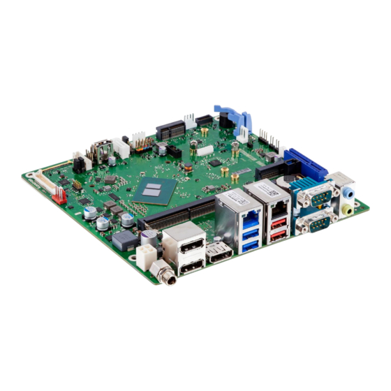
K393x ADL-N Mini-ITX Motherboard
K3931-N Mini-ITX
K3932-N Mini-ITX (CFast)
Table of
Contents
Previous
Page
Next
Page
1
2
3
4
5
Advertisement
Table of Contents
Need help?
Do you have a question about the K393 Series and is the answer not in the manual?
Ask a question
Questions and answers
Related Manuals for Kontron K393 Series
Motherboard Kontron K3931-N Technical Manual
Adl-n mini-itx motherboard (35 pages)
Motherboard Kontron SMARTCASE S501 Assembly Instructions Manual
(17 pages)
Motherboard Kontron K3921 ADL-N Mini-STX Technical Manual
(41 pages)
Motherboard Kontron KTQ87/mITX User Manual
(49 pages)
Motherboard Kontron KTH81/mITX User Manual
(98 pages)
Motherboard Kontron KT690/mITX User Manual
(91 pages)
Motherboard Kontron KT690/mITX User Manual
(60 pages)
Motherboard Kontron KTGM45/mITX User Manual
(100 pages)
Motherboard Kontron KTQ67/Flex User Manual
(113 pages)
Motherboard Kontron KTQ67/ATXE User Manual
(137 pages)
Motherboard Kontron KTG41/ATXu User Manual
(78 pages)
Motherboard Kontron KTQ45/Flex User Manual
Ktq45 series motherboard (92 pages)
Motherboard Kontron KTQM67/mITX User Manual
(148 pages)
Motherboard Kontron KTA55/pITX User Manual
(67 pages)
Motherboard Kontron KTD-N0850-B User Manual
(133 pages)
Motherboard Kontron KTQM87/mITX User Manual
(111 pages)
This manual is also suitable for:
K3931-n
Table of Contents
Print
Rename the bookmark
Delete bookmark?
Delete from my manuals?
Login
Sign In
OR
Sign in with Facebook
Sign in with Google
Upload manual
Upload from disk
Upload from URL


Need help?
Do you have a question about the K393 Series and is the answer not in the manual?
Questions and answers