
Related Manuals for B&G Network Series


Summary of Contents for B&G Network Series
- Page 1 EXCELLENCE IN MARINE ELECTRONICS NETWORK COMPASS MANUAL BROOKES AND GATEHOUSE LTD Premier Way Abbey Park Romsey Hampshire SO51 9AQ England Tel: (+44) 01794 518448 Fax: (+44) 01794 518077 618-HB-0787-01...
-
Page 2: Table Of Contents
CONTENTS CONTENTS .........................1 GENERAL INTRODUCTION TO B&G NETWORK..........2 INTRODUCTION TO NETWORK COMPASS............3 COMPASS DISPLAY UNIT ..................4 EXAMPLE SYSTEMS USING NETWORK COMPASS ........4 SETTING THE DISPLAY BACK LIGHTING............5 THE OFF COURSE DISPLAY..................6 SETTING THE COURSE MEMORIES ..............7 THE XTE DISPLAY ....................8 THE RUDDER DISPLAY ..................9 THE HEAD/LIFT DISPLAY ...................10 USING THE TIMER....................11... -
Page 3: General Introduction To B&G Network
GENERAL INTRODUCTION TO B&G NETWORK Welcome to the B&G Network system. This world beating series of intelligent navigational instruments has been brought to you through a combination of scientific innovation and high quality production to create a computerised data system you can trust. As an intelligent system each unit can be used by itself to display specific data, alternatively any combination of units can be linked into a Network with units processing their own data or acting as repeaters for data from other units. -
Page 4: Introduction To Network Compass
INTRODUCTION TO NETWORK COMPASS The Network COMPASS unit uses the latest advances in electronics to display Off Course, Cross Track Error (XTE)*, Rudder* and Head/Lift information on an easy to read Liquid Crystal Display (LCD). Five keys on the unit select the displayed data, calibration factors and alarms. -
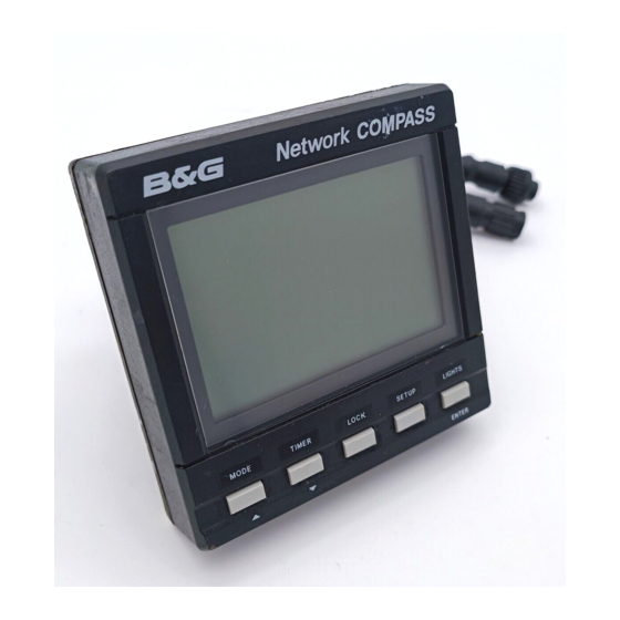
Page 5: Compass Display Unit
COMPASS DISPLAY UNIT Network COMPASS OFFCOURSE STEER PORT CRSE 1 TIMER LOCK SETUP LIGHTS MODE ENTER EXAMPLE SYSTEMS USING NETWORK COMPASS Up to four COMPASS units can be connected to the system. Only one of these should be linked to a fluxgate and set to transducer mode, the other three must be set to repeater mode. -
Page 6: Setting The Display Back Lighting
EXAMPLE SYSTEMS USING NETWORK COMPASS contd. SETTING THE DISPLAY BACK LIGHTING The Network COMPASS display has three brightness settings or off. Pressing the LIGHTS key cycles through these in the following order. • • • • • • • • High •... -
Page 7: The Off Course Display
THE OFF COURSE DISPLAY Pressing the MODE key will cycle the display between Off Course, Cross Track Error (XTE) if GPS is fitted, Rudder angle if Network PILOT fitted and the Head/Lift display (if enabled). Network COMPASS Network COMPASS Network COMPASS RUDDER Network COMPASS LIFT... -
Page 8: Setting The Course Memories
SETTING THE COURSE MEMORIES Whilst in Off Course mode the two course memories may be set. The currently active course memory is shown by the legend CRSE1 or CRSE2. Network COMPASS Network COMPASS OFFCOURSE OFFCOURSE STEER STEER PORT STBD CRSE 2 CRSE 1 MODE TIMER... -
Page 9: The Xte Display
THE XTE DISPLAY REQUIRES A GPS ON THE NETWORK. The Cross Track Error display is used to indicate how far the vessel is from the intended track (from waypoint to waypoint). Network COMPASS STEER PORT MODE TIMER LOCK SETUP LIGHTS ENTER In this instance the vessel is heading starboard of the planned course. -
Page 10: The Rudder Display
THE RUDDER DISPLAY REQUIRES B&G NETWORK PILOT IN CIRCUIT. The rudder display indicates the current angle of the rudder, which is particularly useful on wheel steered boats. Network COMPASS RUDDER MODE TIMER LOCK SETUP LIGHTS ENTER The vessel is turning to starboard, the display shows the current heading and the rudder scale is visible beneath the bar graph which points to port;... -
Page 11: The Head/Lift Display
THE HEAD/LIFT DISPLAY THE HEAD/LIFT PAGE HAS TO BE ENABLED IN THE SET UP MENU before it can be displayed. Network COMPASS Network COMPASS Network COMPASS Network COMPASS LIFT HEAD HEAD LIFT PORT PORT STBD STBD MODE TIMER LOCK SETUP LIGHTS MODE TIMER... -
Page 12: Using The Timer
USING THE TIMER Pressing the TIMER key enters the timer display mode, this is shown by the presence of a colon which flashes every second. Network COMPASS MODE TIMER LOCK SETUP LIGHTS ENTER The timer can be set to any required value to a maximum time period of 99 hours 59 minutes and 50 seconds. -
Page 13: Setting The Timer
SETTING THE TIMER 1. Press TIMER to enter timer mode. 2. Press SETUP to give the display h:xx (xx represents a two digit number) the h will be flashing. 3. Press ENTER and the numbers will flash. 4. Alter the hours using the keys. -
Page 14: Enabling The Off Course Alarm
ENABLING THE OFF COURSE ALARM 1. Press SETUP until the OFFCOURSE legend flashes to indicate the alarm set up display. This value is preset to 0° which is shown as OFF. 2. Press ENTER then OFF will flash. 3. Press the keys to the desired value (between 0°... -
Page 15: Setting The Compass Offset
The compass offset compensates for fixed errors in the compass after installation and calibration such as sensor orientation. 1. Press SETUP until a bearing is displayed and the degrees sign is flashing. 2. Press ENTER, the numbers will flash. 3. Press the keys until the desired value is shown (between +180 and -180 seconds). -
Page 16: Setting The Display For True Or Magnetic Readings
SETTING THE DISPLAY FOR TRUE OR MAGNETIC READINGS 1. Press SETUP until TRUE is flashing and either ON or OFF is displayed. 2. Press ENTER, ON or OFF will flash. 3. Press the keys to switch the setting between on and off 4. -
Page 17: Selecting The Display Mode
SELECTING THE DISPLAY MODE 1. Press SETUP until a flashing t and either r or t is displayed. 2. Press ENTER, r or t will flash. 3. Press the keys to switch the setting between repeater (r) and transducer (t). 4. -
Page 18: Operation With Autopilots
OPERATION WITH AUTOPILOTS REQUIRES A B&G NETWORK AUTOPILOT IN SYSTEM. If a B&G Network autopilot is present in the system, and the unit is set up within a system that includes a Network ACP1 or ACP2 then there are two options for the Network configuration. - Page 19 PROBLEM POSSIBLE CAUSE Display fails to light up Power not connected. Supply not 10 to 16 Volts. Data is not repeated from Network Compass not in repeater mode. Cables not correctly fitted. Compass fails to calibrate (-F-) Calibration manoeuvre performed badly. Compass installed too close to onboard metallic object.
-
Page 20: Installation
INSTALLATION The display heads are supplied with a clip-in mounting bracket which allows for easy installation, access from behind is not necessary to secure the unit in place. However to prevent theft and permanently fix the unit in position, locking studs and thumb nuts are supplied. -
Page 21: Siting The Fluxgate
SITING THE FLUXGATE • Mount the unit upright on a flat vertical bulkhead. • A safe distance from external magnetic interference: 1m/3ft from VHF, RDF, Loudspeakers, depth sounders, engines, power cables carrying heavy current etc. 3m/10ft from Radar and SSB equipment. •... -
Page 22: Installation Data
INSTALLATION DATA 110.0mm 25.0mm 65.0mm Network COMPASS 110.0mm MODE TIMER LOCK SETUP LIGHTS ENTER Locking stud fixing Fluxgate Remote button Network connector Network & Power connector Rubber Gasket Mounting bracket 82.0mm Fit the gasket around the mounting bracket Bulkhead 82.0mm Gasket Sun-cover Display Unit... -
Page 23: Specifications
SPECIFICATIONS PHYSICAL PARAMETERS Display : Backlit Liquid Crystal Display Dimensions : 110 x 110 x 26 mm; 4.25 x 4.25 x 1" A space of 65 mm (2.6") is required behind the bulkhead for display barrel. ENVIRONMENTAL Operating Temp : -10 to +55ºC, +14 to +131º F @ 93% RH Storage Temp : -25 to +70ºC, -25 to +70ºC @ 95% RH Sealing... -
Page 24: Conditions Of Warranty
CONDITIONS OF WARRANTY 1 Brookes & Gatehouse Limited (B&G) warrants B&G NETWORK products, in normal usage, to be free from defects in materials or workmanship for a maximum period of two years (12 months with respect to mechanical items) from purchase by the original owner, subject to the conditions and limitations below. Any part that proves to be defective, in normal usage, during that period will be repaired or replaced by Brookes &... - Page 25 B&G WARRANTY CERTIFICATE SERIAL Nos DISPLAY TRANSDUCER DISTRIBUTORS NAME ADDRESS DEALERS NAME ADDRESS OWNERS NAME ADDRESS DATE OF PURCHASE VESSEL NAME IMPORTANT PLEASE RETAIN THIS DOCUMENT IN A SAFE PLACE...
Need help?
Do you have a question about the Network Series and is the answer not in the manual?
Questions and answers