
Related Manuals for Wacker Neuson E 2200


Summary of Contents for Wacker Neuson E 2200
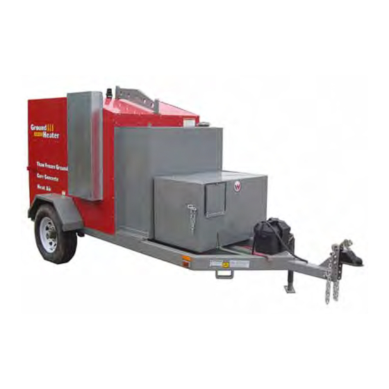
- Page 1 Operator’s Manual Hydronic Surface Heater E 2200 E 3000ES 0192779 1210...
- Page 2 This publication may be photocopied by the original purchaser of the machine. Any other type of reproduction is prohibited without express written permission from Wacker Neuson Corporation. Any type of reproduction or distribution not authorized by Wacker Neuson Corporation represents an infringement of valid copyrights. Violators will be prosecuted. Trademarks All trademarks referenced in this manual are the property of their respective owners.
-
Page 3: Foreword
Use the separate Parts Book supplied with the machine to order replacement parts. If you are missing any of these documents, please contact Wacker Neuson Corporation to order a replacement or visit www.wackerneuson.com. When ordering parts or requesting service information, be prepared to provide the machine model number, item number, revision number, and serial number. - Page 4 Foreword wc_tx001665gb.fm...
-
Page 5: Table Of Contents
E 2200, E 3000ES Table of Contents Foreword Safety Information Signal Words Used in this Manual ............9 Machine Description and Intended Use ..........10 Safety Guidelines for Operating the Machine ........11 Service Safety ..................13 Safety Guidelines for Operating Combustion Burners ....... 15 Safety Guidelines for Operating Gensets ........... - Page 6 Connecting the HX 50 or HX 15 HEAT XCHANGER™ ......70 Combining the Machine with One HHS and One DPP ......72 Combining the Machine with Two HHS and Two DPP (E 2200 only) .74 Mounting the Auxiliary Pump Panel ............76 Burner Setup Adjusting the Burner Electrodes ............80...
- Page 7 E 2200, E 3000ES Table of Contents Troubleshooting Troubleshooting the Machine ............108 Technical Data E 2200 ....................110 E 3000ES ..................111 Trailer ....................112 Dimensions ..................113 MSDS: Dowfrost™ HD 50 Fuji Temperature Controller 10 Schematics 10.1 Electrical Schematic ................. 124 10.2...
- Page 8 E 2200, E 3000ES Table of Contents wc_bo0192779en_001TOC.fm...
-
Page 9: Safety Information
E 2200, E 3000ES Safety Information Safety Information Signal Words Used in this Manual This manual contains DANGER, WARNING, CAUTION, NOTICE, and NOTE signal words which must be followed to reduce the possibility of personal injury, damage to the equipment, or improper service. -
Page 10: Machine Description And Intended Use
In addition, when used with other Wacker Neuson accessories, this machine can be used to heat air. This machine has been designed and built strictly for the intended use(s) described above. -
Page 11: Safety Guidelines For Operating The Machine
Familiarize yourself with the location and proper use of all controls and safety devices. Contact Wacker Neuson Corporation for additional training if necessary. When operating this machine: Do not allow improperly trained people to operate the machine. People operating the machine must be familiar with the potential risks and hazards associated with it. - Page 12 Do not operate the machine if any safety devices or guards are missing or inoperative. Do not modify or defeat the safety devices. Only use accessories or attachments that are approved by Wacker Neuson Corporation. Safe When operating this machine: operating Remain aware of the machine’s moving parts.
-
Page 13: Service Safety
Only trained personnel shall troubleshoot or repair problems occurring with the machine. Contact Wacker Neuson Corporation for additional training if necessary. When servicing or maintaining this machine: Do not allow improperly trained people to service or maintain the machine. - Page 14 Safety Information E 2200, E 3000ES Lifting and When lifting the machine: transporting Make sure slings, chains, hooks, ramps, jacks, and other types of lifting devices are attached securely and have enough weight-bearing capacity to lift or hold the machine safely. See chapter Technical Data.
-
Page 15: Safety Guidelines For Operating Combustion Burners
E 2200, E 3000ES Safety Information Safety Guidelines for Operating Combustion Burners When using the machine: Clean up any spilled fuel immediately. Replace the fuel tank cap after refueling the machine. Refill the fuel tank in a well-ventilated area. Shut down the generator, if equipped, when refueling. -
Page 16: Safety Guidelines For Operating Gensets
Follow instructions carefully. Should questions arise during operation or service of this equipment, contact your Wacker Neuson dealer. Before Know how to start, operate, and stop the genset before starting it. - Page 17 E 2200, E 3000ES Safety Information Do not overload the genset. The total amperage of the tools and equipment attached to the genset must not exceed the load rating of the genset. Do not operate the genset with wet hands.
-
Page 18: Safety Guidelines For Towing The Machine
Safety Information E 2200, E 3000ES Safety Guidelines for Towing the Machine WARNING Risk of severe injury or death. Improper trailer condition and towing technique can lead to an accident. Obey the trailer manufacturer’s instructions and the instructions below to reduce the risk of an accident. - Page 19 E 2200, E 3000ES Safety Information Notes wc_si000540gb.fm...
-
Page 20: Labels
Labels E 2200 / E 3000ES Labels Label Locations 1055 1057 wc_gr008049 wc_si000541gb.fm... - Page 21 E 2200 / E 3000ES Labels 1054 1056 1053 wc_gr008050 wc_si000541gb.fm...
-
Page 22: Label Meanings
Labels E 2200 / E 3000ES Label Meanings — Refer to back of connection box for further connection details. Stop! Do not reset (until HTF leak is repaired and HTF level is restored) Red “LOW LEVEL FAULT” light on control panel indicates HTF is below the minimum operating level. - Page 23 E 2200 / E 3000ES Labels Regularly inspect the rope gasket located between the flue box and the heater vessel CAUTION for visual signs of combustion gas leakage. REGULARLY INSPECT ROPE GASKET Replace the gasket with part number P100- BETWEEN FLUE BOX AND HEATER 312 when needed per the service manual.
- Page 24 Labels E 2200 / E 3000ES Plug in the Pump Pack to this side of the receptacle. — WARNING: Read Operator’s Manual before operating machine. Exhaust gas is deadly. Operate machine only in well ventilated area. Do not operate machine indoors.
- Page 25 E 2200 / E 3000ES Labels Fuel blend guide: This label indicates the proper fuel blending requirements based upon power source and ambient temperature ranges. Consult the Operator’s Manual for more information. WARNING: Attach chains or straps only to axles and designated “tie-down”...
- Page 26 Labels E 2200 / E 3000ES 1053 CAUTION! Hot surface hazard! 1054 WARNING! Hand entanglement hazard! Moving parts can crush and cut. Do not operate with guard removed. 1055 HTF MSDS label. This label is the Material Safety Data Sheet for the HTF installed in the factory.
-
Page 27: Lifting And Transporting
E 2200, E 3000ES Lifting and Transporting Lifting and Transporting Lifting the Machine Requirements Lifting device (crane or hoist) capable of supporting the machine’s weight Lifting hooks and chains capable of supporting the machine’s weight Machine stopped, cooled, and accessories removed. See section Shutting Down and Packing Up the Machine. -
Page 28: Preparing The Machine For Transport On A Truck Or Trailer
Lifting and Transporting E 2200, E 3000ES Preparing the Machine for Transport on a Truck or Trailer Requirements Machine stopped. See topic Shutting Down and Packing Up the Machine. Flatbed truck or trailer capable of supporting the machine’s weight. Chains, hooks, or straps capable of supporting the machine’s weight. -
Page 29: Before Towing Checklist
E 2200, E 3000ES Lifting and Transporting Before Towing Checklist Before towing the machine, check the licensing requirements for trailers in your area. Also check the following items: Hitch and coupler Check that the towing vehicle and hitch have a rating equal to or greater than the GVWR of the machine. -
Page 30: Operation
Operation E 2200 / E 3000ES Operation Control / Component Locations wc_gr008060 wc_tx001667gb.fm... -
Page 31: Control / Component Descriptions
E 2200 / E 3000ES Operation Control / Component Descriptions Ref. Description Ref. Description Lifting bail (optional) Low-level shut-down device Strobe light Temperature/pressure gauge Tie-down bracket Thermocouple Exhaust stack Hydronic heater flue box Reflector HTF filter Battery Pump 1 Jack stand... -
Page 32: Control Panel
Operation E 2200 / E 3000ES Control Panel wc_gr008054 wc_tx001667gb.fm... -
Page 33: Control Panel Components
E 2200 / E 3000ES Operation Control Panel Components Description Function Circuit breaker 1 Controls power to the control circuit (20A) Hour meter Meters usage of the machine. Circuit breaker 2 Controls power to the pump circuit (20A) Line 2 GFCI Provides protection for the operator. -
Page 34: Pumps, Gauges, And Valves
Operation E 2200 / E 3000ES Pumps, Gauges, and Valves wc_gr007816 Pumps and Gauges Ref. Description Ref. Description Return flow indicator Pump 1 Loop 1 return flow temperature Pump 2 Loop 2 return flow temperature Auxiliary return flow indicator Loop 1 supply flow pressure... -
Page 35: Preparing The Machine For First Use
1. Make sure all loose packaging materials have been removed from the machine. 2. Check the machine and its components for damage. If there is visible damage, do not operate the machine! Contact your Wacker Neuson dealer immediately for assistance. -
Page 36: General Sequence Of Operation
Operation E 2200 / E 3000ES General Sequence of Operation Follow the sequence of operation below. Refer to the specific topic for details. Task When/Where See Topic 1. Check HTF level. Before leaving for the job site. 4.10 Or, when at the job site before 2. -
Page 37: Recommended Fuel
E 2200 / E 3000ES Operation Recommended Fuel Low ambient temperatures cause diesel fuels to gel. Gelled fuels will cause burner ignition failure and/or burner fuel pump damage. Always use the proper fuel for the conditions. Fuel Blend Guide Lowest expected ambient... -
Page 38: Positioning The Machine
Do not position the machine on a hill or an incline. CO Alarms Because this machine produces carbon monoxide (CO), Wacker Neuson recommends that CO alarms be installed in all structures in close proximity to the machine. CO alarms provide an extra measure of protection against this poison that you cannot see or smell. - Page 39 E 2200 / E 3000ES Operation Continued from the previous page. Perform the following procedure to position the machine. 1. Place the machine near the application area (a) on solid, stable, and level ground. wc_gr008055 2. For machines with trailers, install chocks (b) under the wheels.
-
Page 40: Pre-Starting Checks
Operation E 2200 / E 3000ES 4.10 Pre-Starting Checks Prerequisites Machine properly positioned Checks Before starting the machine, check the following items: Fuel System Fuel sight gauge valve Check that the fuel sight gauge valve is open. Fuel sight gauge Check that there is fuel in the tank. - Page 41 E 2200 / E 3000ES Operation HTF sight gauge Check that the HTF level is within the operating range. NOTICE: Starting the machine with low HTF will damage the pumps. wc_gr008056 HTF Hose connections Check that all HTF hose quick-connects are secure.
-
Page 42: Connecting Power To The Machine
Operation E 2200 / E 3000ES 4.11 Connecting Power to the Machine Prerequisites Power source Machine properly positioned WARNING Fire hazard and electric shock hazard. The use of under-sized extension cords can lead to fire and electric shock. Fire and electric shock can cause severe injury. -
Page 43: Starting And Stopping The Generator
E 2200 / E 3000ES Operation 4.12 Starting and Stopping the Generator Background Only general starting and stopping procedures for the generator are included in this manual. See the generator manufacturer’s operation manual for detailed procedures. Starting Perform the procedure below to start the generator. -
Page 44: Preheating The Htf
Operation E 2200 / E 3000ES 4.13 Preheating the HTF NOTICE: Starting the machine with frozen or partially frozen Heat Transfer Fluid (HTF) will permanently damage the pumps. Preheat the HTF when ambient air temperature is below -26°C (-15°F). Prerequisites... -
Page 45: Initiating Htf Flow
E 2200 / E 3000ES Operation 4.14 Initiating HTF Flow Prerequisites Heat Transfer Fluid (HTF) preheated. See topic Preheating the HTF Hand protection CAUTION Burn hazard. The hoses and components of the plumbing system may be very hot. Hot hoses and hot plumbing components may cause severe burns. - Page 46 Operation E 2200 / E 3000ES Continued from the previous page. NOTICE: Operate only pump 1 when both hose loops are connected together. Turning on pump 1 and pump 2—with the hoses connected together—may cause pump damage. 4. Connect hose loop 1 (female QC) (f) to the supply port (male QC).
-
Page 47: Setting The Operating Temperature
E 2200 / E 3000ES Operation 4.15 Setting the Operating Temperature Operating Once the HTF is preheated, set the temperature controller to the operating temperature temperature. Use the chart below as a guide. Operation type Recommended Temperature Setting Ground thawing 80°C (180°F) -
Page 48: Positioning The Hoses And Operating The Machine
Operation E 2200 / E 3000ES 4.16 Positioning the Hoses and Operating the Machine Prerequisites “Pre-Starting” checks completed. See topic Pre-Starting Checks. HTF preheated. See topic Preheating the HTF and topic Initiating HTF Flow. CAUTION Hoses may be very hot. You may be burned if proper precautions are not taken. - Page 49 E 2200 / E 3000ES Operation 7. Connect loop 2 (female quick connect) to the supply port (e). 8. Unwind loop 2 from the hose reel and position it within the application area. Use caution when nearing the end of the hose loop so that the hose loop is not damaged due to over spinning of the hose reel.
-
Page 50: Monitoring The Operating Parameters
The HTF return temperature tells you how much heat is being transferred. It can also tell you when a thawing process is complete, as very little heat will be transferred at that point. Consult Wacker Neuson Product Support for detailed information. Strobe light Flashing strobe signifies that all systems are OK. -
Page 51: Stopping The Machine Temporarily
E 2200 / E 3000ES Operation 4.18 Stopping the Machine Temporarily Precautions NOTICE: This procedure is to be used for stopping the machine temporarily for routine maintenance such as refueling or repositioning hoses. Do not use this pro- cedure for any other purpose. -
Page 52: Rewinding The Hoses
Operation E 2200 / E 3000ES 4.19 Rewinding the Hoses Requirements All accessories off, if applicable Machine turned on CAUTION Hot surface hazard. Hoses may be very hot. Wear hand protection while handling hoses. Procedure Perform the procedure below to rewind the hose. - Page 53 E 2200 / E 3000ES Operation Continued from the previous page. NOTICE: Disengage the clutch (release the foot pedal) before reaching the hose end. Failure to do so may damage the machine. 7. Release the foot pedal to disengage the clutch approximately six feet from the end of the hose.
-
Page 54: Shutting Down And Packing Up The Machine
Operation E 2200 / E 3000ES 4.20 Shutting Down and Packing Up the Machine Shutting Perform the procedure below to shut down the machine. down 1. Move the burner ON-OFF switch (a) to the OFF position. wc_gr008066 2. Move the pump ON-OFF switches (b and b ) to the OFF position. -
Page 55: Resetting A Low Htf Level Fault
E 2200 / E 3000ES Operation 4.21 Resetting a Low HTF Level Fault Requirements Genuine Wacker Neuson Heat Transfer Fluid Power connected to the machine NOTICE: Use only factory-recommended Heat Transfer Fluid (HTF). Failure to do so may damage the machine. - Page 56 Operation E 2200 / E 3000ES Continued from the previous page. 4. Place the open end of the fill hose into a container of HTF. 5. Move and hold the bypass switch (x) in the ON position. HTF will begin to flow.
- Page 57 E 2200 / E 3000ES Operation Continued from the previous page. 2. Move the fill valve (3) to the CLOSED position and insert the pin. wc_gr007810 3. Move the operation valve (2) to the OPEN position. 4. Clean the fill hose, and cap the fill hose if a cap is provided.
-
Page 58: Quick-Connect Coupling Usage And Care
Operation E 2200 / E 3000ES 4.22 Quick-Connect Coupling Usage and Care CAUTION Burn hazard. The hoses and components of the plumbing system may be very hot. Hot hoses and hot plumbing components may cause severe burns. Wear gloves when handling hot hoses and plumbing components. -
Page 59: Resetting The Snap Switch
E 2200 / E 3000ES Operation 4.23 Resetting the Snap Switch Background The thermal overload switch (snap switch) opens when the temperature of the Heat Transfer Fluid (HTF) reaches 88°C (190°F). When the snap switch opens, electric power is disconnected from the burner. The snap switch must be manually reset to reconnect power to the burner. -
Page 60: Burner Controller Periods And Modes
Operation E 2200 / E 3000ES 4.24 Burner Controller Periods and Modes Periods The burner controller has several periods it sequences through during normal operation. These periods are described below. Period Action or Function Power up As soon as power is supplied to the burner controller, it conducts an internal safety check. - Page 61 E 2200 / E 3000ES Operation Period Action or Function Trial-for- The trial-for-ignition period immediately follows the valve-on-delay ignition period. During this period: The fuel shut-off valve is opened (energized). Pressurized fuel atomizes at the burner nozzle. The atomized fuel is vaporized and ignited by the electrodes.
- Page 62 Operation E 2200 / E 3000ES Mode Functional description Startup The burner controller will enter the startup mode as soon as there is a call for heat. This mode consists of the following periods: Safety Valve-on-delay Trial-for-ignition Carry-over The run mode starts and continues once the ignition carry-over period has elapsed.
- Page 63 E 2200 / E 3000ES Operation Continued from the previous page. Fault modes The burner controller fault modes are described below. Lockout The burner will enter the lockout mode after three unsuccessful attempts to re-light the flame. During the lockout mode: The burner will not fire.
- Page 64 Operation E 2200 / E 3000ES Notes wc_tx001667gb.fm...
-
Page 65: Accessories
E 2200, E 3000ES Accessories Accessories Available Accessories To increase the machine’s capabilities and capacities, the following Wacker Neuson accessories are available. Description Ref. Description Hose Handling System (HHS3002) 1-2 Adapter HEAT XCHANGER™ (HX 50) 2-1 Adapter HEAT XCHANGER™ (HX 100) Accessory hoses (various lengths) HEAT XCHANGER™... -
Page 66: Connecting The Hx 200 Or Hx 60 Heat Xchanger
Accessories E 2200, E 3000ES Connecting the HX 200 or HX 60 HEAT XCHANGER™ Requirements Machine stopped One HEAT XCHANGER (HX 60 or HX 200) Hose: 2 pieces of 5/8-in. ID or 1-in. ID with quick-connect fittings Limitations Maximum run (horizontal distance from HX to machine): 228 m (750 ft) - Page 67 E 2200, E 3000ES Accessories Continued from the previous page. 3. Open valve (4). HX 60 HX 200 wc_gr007814 4. Position the HEAT XCHANGER within the space to be heated. 5. Connect the HEAT XCHANGER supply hose (a) to the HTF supply line (b).
-
Page 68: Connecting The Hx 100 Or Hx 30 Heat Xchanger
Accessories E 2200, E 3000ES Connecting the HX 100 or HX 30 HEAT XCHANGER™ Requirements Machine stopped One HEAT XCHANGER (HX 100 or HX 30) Hose: For runs longer than 12 m (40 ft), 2 pieces of 5/8-in. ID with quick-connect... - Page 69 E 2200, E 3000ES Accessories Continued from the previous page. 3. Close valve (4). E 3000ES HX 30 HX 30 wc gr007817 4. Position the HEAT XCHANGERS within the space to be heated. 5. Connect the HEAT XCHANGER supply hoses (a) to the HTF supply line (b).
-
Page 70: Connecting The Hx 50 Or Hx 15 Heat Xchanger
Accessories E 2200, E 3000ES Connecting the HX 50 or HX 15 HEAT XCHANGER™ Requirements Machine stopped One HEAT XCHANGER (HX 50 or HX 15) Hose: For runs longer than 12 m (40 ft), 2 pieces of 5/8-in. ID with quick-connect... - Page 71 E 2200, E 3000ES Accessories Continued from the previous page. 3. Close valve (4). HX 50 HX 50 HX 50 HX 50 HX 15 HX 15 HX 15 HX 15 wc_gr007818 4. Position the HEAT XCHANGERS within the space to be heated.
-
Page 72: Combining The Machine With One Hhs And One Dpp
Accessories E 2200, E 3000ES Combining the Machine with One HHS and One DPP Requirements Machine stopped Hose Handling System (HHS) Dual Pump Pack (DPP) Procedure Perform the procedure below to connect an HHS and a DPP to the machine. - Page 73 E 2200, E 3000ES Accessories Electrical Make the following electrical connections. connections Connect the power cord from the DPP (e) to the auxiliary receptacle labeled “PUMP PACK” (b). wc_gr008081 Operating 1. Start the parent machine. Turn on the buner and the pumps.
-
Page 74: Combining The Machine With Two Hhs And Two Dpp (E 2200 Only)
Accessories E 2200, E 3000ES Combining the Machine with Two HHS and Two DPP (E 2200 only) Requirements Machine stopped Two Hose Handling Systems (HHS) Two Dual Pump Packs (DPP) Two 2–1 adapters One Auxiliary Pump Panel (APP). See topic Mounting the Auxiliary Pump Panel Procedure Perform the procedure below to connect two HHS and two DPP to the machine. - Page 75 E 2200, E 3000ES Accessories 3. Remove hose loop 2 from the HHS and store the HHS in a secure location. 4. Connect HHS hose loop 2 (h ) to discharge port (g ) of DPP1. DPP 2 and Connect the hoses from HHS 2 to the machine and to DPP 2 in the same manner HHS 2 as connecting DPP 1.
-
Page 76: Mounting The Auxiliary Pump Panel
Power disconnected Auxiliary Pump Panel Background The Wacker Neuson Auxiliary Pump Panel (APP) is an electrical device that communicates with the main machine’s systems to provide protection for any additional Pump Packs that are connected to the machine. If the machine experiences a low level fault condition, the APP will cut off power to the external components. -
Page 77: Burner Setup
E 2200, E 3000ES Burner Setup Burner Setup Factory settings Firing rate Nozzle Fuel pressure Air band Adjusting Head L/hr (gph) size bar (psi) setting shutter plate 6.8 (1.80) 1.35 70° B 12.4 (180) Background The burner consists of several different components and subsystems. Each of these components or subsystems must be operating correctly for the burner to function properly. - Page 78 Burner Setup E 2200, E 3000ES Continued from the previous page. When Adjust the burner: Before operating the machine at elevations 305 m (1,000 ft) above or below the location of the previous adjustments Before starting at a new job site...
- Page 79 E 2200, E 3000ES Burner Setup Continued from the previous page. 9. Analyze the combustion. Follow the combustion analyzer manufacturer’s instructions and the general guidelines below. Use the access hole in the exhaust stack. Take several samples as the heater warms.
-
Page 80: Adjusting The Burner Electrodes
Burner Setup E 2200, E 3000ES Adjusting the Burner Electrodes Requirements Power supplies disconnected Measuring device Procedure Follow the procedure below to check the electrodes. 1. Shut down the machine and disconnect the power supplies. 2. Remove the copper fuel line (a) between the fuel pump and the burner housing. - Page 81 E 2200, E 3000ES Burner Setup Continued from the previous page. 7. Use the measurements below to properly set the electrode tips. Ref. Description Gap distance Electrode tip to electrode tip 5/32 in. (4 mm) Nozzle center to electrode tip 5/16 in.
- Page 82 Burner Setup E 2200, E 3000ES Continued from the previous page. 5. Install the splined knob (b). Note: Handle the knurled knob with care. It is easily damaged. 6. Install the copper fuel line (a) between the fuel pump and the burner housing.
-
Page 83: Replacing The Burner Nozzle
E 2200, E 3000ES Burner Setup Replacing the Burner Nozzle Prerequisites Power supplies disconnected Machine cool Removal Follow the procedure below to remove the burner nozzle. 1. Disconnect the power supplies. 2. Remove the copper fuel line (a) between the fuel pump and the burner housing. - Page 84 Burner Setup E 2200, E 3000ES Continued from the previous page. 7. Unscrew the burner nozzle (e) from the burner tube. wc_gr008114 The procedure to remove the burner nozzle is now complete. Installation Follow the procedure below to install the burner nozzle.
- Page 85 E 2200, E 3000ES Burner Setup Continued from the previous page. 5. Install the splined knob (b). Note: Handle the knurled knob with care. It is easily damaged. 6. Install the copper fuel line (a) between the fuel pump and the burner housing.
-
Page 86: Setting The "Z" Distance On V1-Style Heads
Burner Setup E 2200, E 3000ES Setting the “Z” Distance on V1-Style Heads Requirements Burner removed from the machine T501 gauge or straight edge and measuring device Preliminary Follow the procedure below to set the “Z” distance on V1-style heads. - Page 87 E 2200, E 3000ES Burner Setup Continued from the previous page. 4. Tighten the hex head screw. 5. Tighten the splined nut. 6. Reconnect the oil connector tube. Result The “Z” distance has now been set. Continue by setting the head position adjusting plate.
-
Page 88: Adjusting The Air Settings
Burner Setup E 2200, E 3000ES Adjusting the Air Settings Background There are two parts to adjusting the air setting: 1) air band; and 2) air shutter. Adjust the air band to make large adjustments. Adjust the air shutter to make small adjustments. -
Page 89: Setting The Fuel Pressure
E 2200, E 3000ES Burner Setup Setting the Fuel Pressure Requirements Pressure gauge See Factory Settings chart in topic Burner Setup for fuel pressure reading Procedure Follow the procedure below to check and adjust the fuel pressure. 1. Shut down the machine. - Page 90 Burner Setup E 2200, E 3000ES Notes wc_tx001669gb.fm...
-
Page 91: Maintenance
E 2200, E 3000ES Maintenance Maintenance Periodic Maintenance Schedule The table below lists basic machine maintenance. Tasks designated with check marks may be performed by the operator. Tasks designated with square bullet points require special training and equipment. Refer to the generator manufacturer’s operation manual for generator maintenance procedures. -
Page 92: Repairing A Hose
Maintenance E 2200, E 3000ES Repairing a Hose Requirements Hose nipple Two hose ferrules Hose crimping tool, part number 0169002 Procedure Follow the procedure below to repair a damaged hose. 1. Shut down the machine and allow the Heat Transfer Fluid (HTF) to cool. - Page 93 E 2200, E 3000ES Maintenance Continued from the previous page. 7. Use a Wacker Neuson brand hose crimper (e) to crimp both ferrules. 8. Rotate the hose 90 degrees and crimp both ferrules again. The procedure is now complete. wc_tx001670gb.fm...
-
Page 94: Inspecting The Htf System And The Fuel System
Maintenance E 2200, E 3000ES Inspecting the HTF System and the Fuel System Requirements Machine shut down Burner cool HTF System Hoses: 1. Rotate the hose reel brake T-handle counterclockwise to release the brake. 2. Unwind all the hose off the reel. Inspect the hose for leaks and/or damage. -
Page 95: Inspecting Electrical Cords
E 2200, E 3000ES Maintenance Inspecting Electrical Cords Requirements Machine stopped Circuit breaker off All power disconnected from machine Procedure 1. Open all access doors and remove all access covers. 2. Inspect control panel and associated electrical cords for wear and/or damage. -
Page 96: Filling The Htf Reservoir
Maintenance E 2200, E 3000ES Filling the HTF Reservoir Requirements Genuine Wacker Neuson Heat Transfer Fluid Machine is on a level surface NOTICE: Use only factory-recommended Heat Transfer Fluid (HTF). Failure to comply may damage the machine. Background The procedure for routine filling of the HTF reservoir differs slightly from that when a low level fault is encountered. - Page 97 E 2200, E 3000ES Maintenance Continued from the previous page. Fill the HTF 5. Move and hold the bypass switch (x) in the ON position. HTF will begin to flow. reservoir When the HTF is level is between the minimum and maximum marks on the sightglass (c): a.
-
Page 98: Cleaning The Htf Strainer
Maintenance E 2200, E 3000ES Cleaning the HTF Strainer Requirements Machine shut down Source of clean, warm water Removal Perform the procedure below to clean the HTF strainer. Note: In the interests of environmental protection, place a plastic sheet and a container under the machine to collect any liquid which drains off. - Page 99 E 2200, E 3000ES Maintenance Continued from the previous page. Installation 1. Inspect the strainer gasket (f) and replace it if it is damaged. 2. To ensure strainer gasket (f) placement, install the canister (b) over the strainer basket (c).
-
Page 100: Replacing The Fuel Filter
Maintenance E 2200, E 3000ES Replacing the Fuel Filter Requirements Machine shut down New fuel filter element and gasket kit Removal NOTICE: Do not remove the fuel filter assembly from the machine unless the filter housing cap needs to be replaced. -
Page 101: Lubricating The Hose Reel System
E 2200, E 3000ES Maintenance Lubricating the Hose Reel System Requirements Machine shut down Machine cool Procedure Perform the procedure below to lubricate the hose reel system. 1. Disconnect electric power from the machine. 2. Apply low temperature bearing grease, with several pumps from a grease gun, to each bearing (a). -
Page 102: Cleaning The Turbulators And The Exhaust Ducting
Maintenance E 2200, E 3000ES Cleaning the Turbulators and the Exhaust Ducting Requirements Machine shut down Machine cool Procedure Follow the procedure below to clean/change the turbulator tubes. 1. Allow the machine to cool. WARNING Burn hazard. The hydronic heater is very hot when the machine is operating. When hot it can cause severe burns. - Page 103 E 2200, E 3000ES Maintenance 8. Remove the exhaust stack (e) (both inner and outer panels). wc_gr008079 9. Vacuum out the exhaust ducting (f) and the heater. 10.Reinstall the exhaust stack. 11.Reassemble the machine. Result The procedure is now complete.
-
Page 104: Inspecting/Replacing The Rope Gasket
Maintenance E 2200, E 3000ES 7.10 Inspecting/Replacing the Rope Gasket Requirements Machine shut down Machine cool Integrity Follow the procedure below to confirm the integrity of the flue box rope gasket. inspection 1. Allow the machine to cool. WARNING Burn hazard. The hydronic heater is very hot when the machine is operating. When hot it can cause severe burns. -
Page 105: Storing The Machine
E 2200, E 3000ES Maintenance 7.11 Storing the Machine Short-term 1. Fill the HTF reservoir if it is low. storage 2. Stop the machine. See topic Shutting Down and Packing Up the Machine. 3. Remove and store any accessories. 4. Allow the heater to cool sufficiently. -
Page 106: Preparing The Machine For Seasonal Operation
Maintenance E 2200, E 3000ES 7.12 Preparing the Machine for Seasonal Operation Background After removing the machine from long-term storage, it must be prepared for operation. Perform the procedures below before each seasonal use. Before Perform the procedures below before you power up the machine. - Page 107 E 2200, E 3000ES Maintenance Notes wc_tx001670gb.fm...
-
Page 108: Troubleshooting
Troubleshooting E 2200, E 3000ES Troubleshooting Troubleshooting the Machine Problem / Symptom Reason Remedy The burner does not start. Improper switch position or Verify that the breaker is protective function action. ON. Verify that the HTF level is within range and low... - Page 109 E 2200, E 3000ES Troubleshooting Problem / Symptom Reason Remedy Thaw progress is below The insulation is insuffi- Add additional insulation capacity. cient. blankets. The moisture is insufficient. Verify that there is standing water on job site. There is no vapor barrier.
-
Page 110: Technical Data
Technical Data E 2200, E 3000ES Technical Data E 2200 Item No. Item No. Item No. Item No. E 2200 Units 0620176 0620215 0620216 0620226 Weight, no fuel, no genera- kg (lb) 2139 (4715) Weight, full fuel, no genera- kg (lb) -
Page 111: E 3000Es
E 2200, E 3000ES Technical Data E 3000ES Item No. Item No. E 3000ES Units 0620967 0620968 Weight, no fuel kg (lb) 2250 (4960) 2250 (4960) Weight, full fuel kg (lb) 2597 (5725) 2597 (5725) Generator weight kg (lb) 238 (525) -
Page 112: Trailer
Technical Data E 2200, E 3000ES Trailer Item Number E 2200 E 3000ES Model Axle rating kg (lb) 2722 (6000) 3175 (7000) Wheel diameter mm (in.) 381 (15) 406 (16) Wheel code – Y701500 16x6K 16x6K Wheel rating kg (lb) -
Page 113: Dimensions
E 2200, E 3000ES Technical Data Dimensions cm (in.) wc_td000422gb.fm... -
Page 114: Msds: Dowfrost™ Hd 50
MSDS: Dowfrost™ HD 50 MSDS: Dowfrost™ HD 50 Material Safety Data Sheet The Dow Chemical Company Product Name: DOWFROST* HD 50 Heat Transfer Fluid, Dyed Issue Date: 12/10/2007 Print Date: 01 Sep 2010 The Dow Chemical Company encourages and expects you to read and understand the entire (M)SDS, as there is important information throughout the document. - Page 115 MSDS: Dowfrost™ HD 50 Product Name: DOWFROST* HD 50 Heat Transfer Fluid, Dyed Issue Date: 12/10/2007 Ingestion: Very low toxicity if swallowed. Harmful effects not anticipated from swallowing small amounts. Effects of Repeated Exposure: In rare cases, repeated excessive exposure to propylene glycol may cause central nervous system effects.
- Page 116 MSDS: Dowfrost™ HD 50 Product Name: DOWFROST* HD 50 Heat Transfer Fluid, Dyed Issue Date: 12/10/2007 +DQGOLQJ DQG 6WRUDJH Handling General Handling: No special precautions required. Spills of these organic materials on hot fibrous insulations may lead to lowering of the autoignition temperatures possibly resulting in spontaneous combustion.
- Page 117 MSDS: Dowfrost™ HD 50 Product Name: DOWFROST* HD 50 Heat Transfer Fluid, Dyed Issue Date: 12/10/2007 Upper: 12.5 %(V) Literature Propylene glycol Autoignition Temperature 371 ° C (700 ° F) Literature Propylene glycol Vapor Pressure 15.5 mmHg @ 20 ° C Literature Boiling Point (760 mmHg) 104 °...
- Page 118 MSDS: Dowfrost™ HD 50 Product Name: DOWFROST* HD 50 Heat Transfer Fluid, Dyed Issue Date: 12/10/2007 (FRORJLFDO ,QIRUPDWLRQ &+(0,&$/ )$7( Movement & Partitioning For the major component(s): Bioconcentration potential is low (BCF less than 100 or log Pow less than 3). Potential for mobility in soil is very high (Koc between 0 and 50). Persistence and Degradability For the major component(s): Material is readily biodegradable.
- Page 119 MSDS: Dowfrost™ HD 50 Product Name: DOWFROST* HD 50 Heat Transfer Fluid, Dyed Issue Date: 12/10/2007 5HJXODWRU\ ,QIRUPDWLRQ OSHA Hazard Communication Standard This product is not a "Hazardous Chemical" as defined by the OSHA Hazard Communication Standard, 29 CFR 1910.1200. Superfund Amendments and Reauthorization Act of 1986 Title III (Emergency Planning and Community Right-to-Know Act of 1986) Sections 311 and 312 Immediate (Acute) Health Hazard...
- Page 120 MSDS: Dowfrost™ HD 50 Product Name: DOWFROST* HD 50 Heat Transfer Fluid, Dyed Issue Date: 12/10/2007 Most recent revision(s) are noted by the bold, double bars in left-hand margin throughout this document. Legend Not available Weight/Weight Occupational Exposure Limit STEL Short Term Exposure Limit Time Weighted Average ACGIH...
-
Page 121: Fuji Temperature Controller
Fuji Temperature Controller Fuji Temperature Controller Fuji Temperature Controller Hysteresis (differential) Adjusting wc_tx001673gb.fm... - Page 122 Fuji Temperature Controller Fuji Temperature Controller Low Temperature Limit Adjusting wc_tx001673gb.fm...
- Page 123 Fuji Temperature Controller Fuji Temperature Controller High Temperature Limit Adjusting wc_tx001673gb.fm...
-
Page 124: Schematics
Schematics E 2200, E 3000ES 10 Schematics 10.1 Electrical Schematic wc_tx001672gb.fm... -
Page 125: Electrical Schematic Components
E 2200, E 3000ES Schematics 10.2 Electrical Schematic Components Use the following table of symbols for the schematics found throughout this chapter. Symbol Description Circuit breaker 1 GFCI 1 Ground Fault Circuit Interrupt 1 Fuse 1 HOSE Hose rewind Off/On switch... - Page 126 Schematics E 2200, E 3000ES Symbol Description Fuse 3 LOW LEVEL Low-level shut down device power connection terminals LOW LEVEL Low-level shut down device normally open contacts Pumps, enable Pump pack Relay coil (K1) Relay normally open contacts (K1) Relay coil (K2)
- Page 127 E 2200, E 3000ES Schematics Symbol Description SOL 2 Solenoid 2 (Oil valve) T/C type T Thermocouple Type T TEMP. Temp. (temperature) controller CONTROLLER Cab light CAB LIGHT Cab light Off/On switch CB 2 Circuit breaker 2 GFCI 2 Ground Fault Circuit Interrupt 2...
-
Page 128: Burner System Circuit
Schematics E 2200, E 3000ES 10.3 Burner System Circuit wc_tx001672gb.fm... -
Page 129: Circulation System Circuit
E 2200, E 3000ES Schematics 10.4 Circulation System Circuit ghi_gr005662 wc_tx001672gb.fm... -
Page 130: Rewind System Circuit
Schematics E 2200, E 3000ES 10.5 Rewind System Circuit wc_tx001672gb.fm... - Page 132 Fax: +49 - (0)89-3 54 02-390 Wacker Neuson Corporation · N92W15000 Anthony Ave. · Menomonee Falls, WI 53051 · Tel. : (262) 255-0500 · Fax: (262) 255-0550 ·Tel. : (800) 770-0957 Wacker Neuson Limited - Room 1701–03 & 1717–20, 17/F. Tower 1, Grand Century Place, 193 Prince Edward Road West, Mongkok, Kowloon, Hongkong.
Need help?
Do you have a question about the E 2200 and is the answer not in the manual?
Questions and answers