
Related Manuals for Wacker Neuson E1100


Summary of Contents for Wacker Neuson E1100
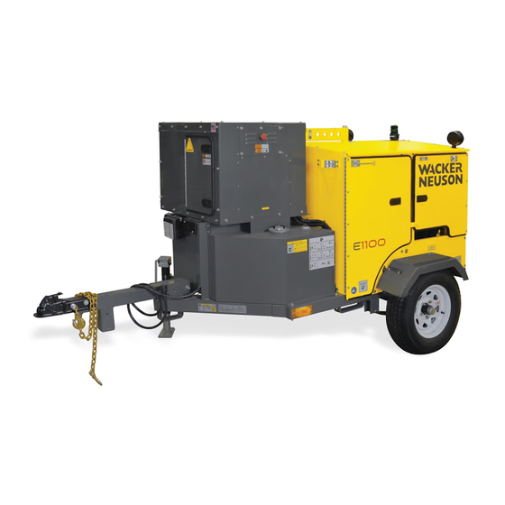
- Page 1 Operator’s Manual Hydronic Surface Heater E1100 E1100 DG Type E1100, E1100 DG Document 5200003474 Date 1115 Version Language 5 2 0 0 0 0 3 4 7 4...
- Page 2 Copyright notice © Copyright 2015 by Wacker Neuson Production Americas LLC All rights, including copying and distribution rights, are reserved. This publication may be photocopied by the original purchaser of the machine. Any other type of reproduction is prohibited without express written permission from Wacker Neuson Production Americas LLC.
-
Page 3: Foreword
The information contained in this manual is based on machines manufactured up until the time of publication. Wacker Neuson reserves the right to change any portion of this information without notice. The illustrations, parts, and procedures in this manual refer to Wacker Neuson factory-installed components. - Page 4 Serious injury hazards to the operator and persons in the work area Permanent damage to the machine which will not be covered under warranty Contact your Wacker Neuson dealer immediately if you have questions about approved or unapproved parts, attachments, or modifications.
-
Page 5: Table Of Contents
E 1100 Table of Contents Foreword Safety Information Signal Words Used in this Manual ............9 Machine Description and Intended Use ..........10 Safety Guidelines for Operating the Machine ........11 Safety Guidelines for Lifting and Transporting the Machine ....12 Safety Guidelines for Towing the Machine ......... - Page 6 Table of Contents E 1100 4.14 Connecting Power to the Machine ............50 4.15 Powering Up the Machine ..............51 4.16 Preheating the HTF ................52 4.17 Initiating the HTF Flow ................ 53 4.18 Unwinding and Positioning the Hoses ..........54 4.19 Hose Spacing Guidelines ..............
- Page 7 E 1100 Table of Contents Repairing a Hose ................94 Inspecting Electrical Cords ..............96 Filling the HTF Reservoir ..............97 Cleaning the HTF Strainer ..............98 7.10 Replacing the Fuel Filter ..............100 7.11 Lubricating the Hose Reel System ........... 101 7.12 Storing the Machine .................
- Page 8 Table of Contents E 1100 11.2 E 1100 Components ................. 148 11.3 Burner System Circuit ............... 151 11.4 Circulation System Circuit ..............152 11.5 Rewind System Circuit ..............153 11.6 Trailer Plug — Wiring Diagram ............154 11.7 Trailer Junction Box — Wiring Diagram ..........155 11.8 Trailer Lights and Brakes —...
-
Page 9: Safety Information
E 1100 Safety Information Safety Information Signal Words Used in this Manual This manual contains DANGER, WARNING, CAUTION, NOTICE, and NOTE signal words which must be followed to reduce the possibility of personal injury, damage to the equipment, or improper service. This is the safety alert symbol. -
Page 10: Machine Description And Intended Use
In addition, when used with other Wacker Neuson accessories, this machine can be used to heat air. This machine has been designed and built strictly for the intended use(s) described above. -
Page 11: Safety Guidelines For Operating The Machine
Familiarize yourself with the location and proper use of all controls and safety devices. Contact Wacker Neuson for additional training if necessary. When operating this machine: Do not allow improperly trained people to operate the machine. People operating the machine must be familiar with the potential risks and hazards associated with it. -
Page 12: Safety Guidelines For Lifting And Transporting The Machine
Do not operate the machine if any safety devices or guards are missing or inoperative. Do not modify or defeat the safety devices. Only use accessories or attachments that are approved by Wacker Neuson. Guidelines for When operating the machine: operator Remain aware of the machine’s moving parts. -
Page 13: Safety Guidelines For Towing The Machine
E 1100 Safety Information Safety Guidelines for Towing the Machine WARNING Risk of severe injury or death. Improper trailer condition and towing technique can lead to an accident. Obey the trailer manufacturer’s instructions and the instructions below to reduce the risk of an accident. When towing the machine: Do not tow the machine if the towing vehicle’s hitch or the trailer’s coupler are damaged. -
Page 14: Safety Guidelines For Operating Combustion Burners
Safety Information E 1100 Safety Guidelines for Operating Combustion Burners Burner safety When using the machine: Clean up any spilled fuel immediately. Replace the fuel tank cap after refueling the machine. Refill the fuel tank in a well-ventilated area. DANGER Exhaust gas from the burner contains carbon monoxide, a deadly poison. -
Page 15: Safety Guidelines For Operating Gensets
Follow instructions carefully. Should questions arise during operation or service of this equipment, contact your Wacker Neuson dealer. General Keep a multi-class, type ABC or equivalent fire extinguisher at hand when using precautions the genset. - Page 16 Safety Information E 1100 Before Know how to start, operate, and stop the genset before starting it. operating the Obtain the proper training for operating the genset. Do not allow untrained genset personnel to operate or service the genset. Check the fuel lines and the fuel tank for leaks and cracks before starting the engine.
-
Page 17: Service Safety
Machine When servicing or maintaining the machine: modifications Use only accessories/attachments that are approved by Wacker Neuson. When servicing or maintaining the machine: Do not defeat safety devices. Do not modify the machine without the express written approval of Wacker Neuson. - Page 18 Safety Information E 1100 When cleaning the machine: Do not clean the machine while it is running. Never use gasoline or other types of fuels or flammable solvents to clean the machine. Fumes from fuels and solvents can become explosive. Personal Wear the following Personal Protective Equipment (PPE) while servicing or Protective...
- Page 19 E 1100 Safety Information Notes wc_si000628gb.fm...
-
Page 20: Labels
Labels E 1100 Labels Label Locations wc_gr009588 wc_si000629gb.fm... -
Page 21: Label Meanings
E 1100 Labels Label Meanings Forklift lift point WARNING Hot surface Caution: Lift point. CAUTION Attach lifting device in this location. VORSICHT PRECAUCION PRECAUTION Fuel blend guide: This label indicates the proper fuel blending requirements based upon power source and ambient temperature ranges. - Page 22 Labels E 1100 CAUTION WARNING Hot surface hazard Wear hand protection. WARNUNG Wear eye protection. ADVERTENCIA AVERTISSEMENT 173199 Tie-down location marker: This label indicates areas on the machine that may be used for securing the machine during transport or storage. Heat Transfer Fluid level.
- Page 23 E 1100 Labels Valve operation label This label indicates the functions of the oper- ational positions for valve #2. 176351 DANGER Asphyxiation hazard. Using a Hydronic Surface Heater indoors CAN KILL YOU IN MINUTES. Generator and burner exhaust contains carbon monoxide. This is a poison you cannot see or smell.
- Page 24 Labels E 1100 To start the machine (I): 1. Check the level of the Heat Transfer Fluid. Also check the level of fuel in the diesel fuel tank. 2. Connect the machine to the electric power source. 3. Move the circuit breaker switch to the ON position. Also press the ON/ OFF switch.
- Page 25 E 1100 Labels WARNING: Lug nuts factory-torqued to 75 ft.lbs. Verify lug nuts are properly torqued before trans- porting. Failure to heed warning could result in wheel loss which can cause injury or death. Do not reset. Refer to Operator’s Manual. VIN and Tire and Loading Information labels.
- Page 26 Labels E 1100 Burner setup. This label indicates important setup informa- tion for the burner. CAUTION! CAUTION Pressurized contents. Do not open when hot! VORSICHT ATENCION ATTENTION 183255 WARNING! WARNING WARNING WARNUNG WARNUNG Electric shock hazard inside. Disconnect ADVERTENCIA ADVERTENCIA electrical connections and read the Opera- AVERTISSEMENT AVERTISSEMENT...
- Page 27 E 1100 Labels WARNING Explosion hazard. Do not use evaporative starting fluids such as ether on this engine. The engine is equipped with a cold starting aid. Using evaporative starting fluids can cause an explosion which can cause engine damage, personal injury, or death. Read and follow the engine starting instructions in this Operator's Manual.
- Page 28 Labels E 1100 A nameplate listing the model number, item number, revision number, and serial number is attached to each unit. Please record the information found on this plate so it will be available should the nameplate become lost or damaged. When ordering parts or requesting service information, you will always be asked to specify the model num- ber, item number, revision number, and serial...
-
Page 29: Lifting And Transporting
E 1100 Lifting and Transporting Lifting and Transporting Lifting the Machine Requirements Properly-rated lifting equipment (crane or hoist) Machine stopped All doors and access covers closed and secured WARNING Crushing hazard. You may be crushed if the lifting devices fail. Never stand under, or get onto, the machine while it is being lifted or moved. -
Page 30: Preparing The Machine For Transport On A Truck Or Trailer
Lifting and Transporting E 1100 Preparing the Machine for Transport on a Truck or Trailer Requirements Machine stopped. Flatbed truck or trailer capable of supporting the machine’s weight. Chains, hooks, or straps capable of supporting the machine’s weight. WARNING Crushing hazard. Improperly securing the machine can lead to a crushing hazard. Use only the designated tie-down points to secure the machine to a truck or trailer. -
Page 31: Transporting The Machine On A Truck Or Trailer
E 1100 Lifting and Transporting Transporting the Machine on a Truck or Trailer Requirements Machine stopped All doors and access covers closed and secured Properly-rated ramps or docks Properly-rated chains or straps WARNING Crushing hazard. Improperly securing the machine can lead to a crushing hazard. Use only the designated tie-down points to secure the machine. -
Page 32: Before Towing Checklist
Lifting and Transporting E 1100 Before Towing Checklist Before towing the machine, check the licensing requirements for trailers in your area. Also check the following items: Hitch and coupler Check that the towing vehicle and hitch have a rating equal to or greater than the GVWR of the machine. -
Page 33: Towing The Machine
E 1100 Lifting and Transporting Towing the Machine WARNING Risk of severe injury or death. Improperly torqued lug nuts can lead to loss of wheels. Loss of wheels can cause an accident, severe injury or death. Tighten the lug nuts to the proper torque before towing the machine. NOTICE: The towing vehicle must be equipped with a Class III or above hitch. -
Page 34: Testing The Breakaway System (Electric Brakes)
Lifting and Transporting E 1100 Testing the Breakaway System (Electric Brakes) Requirements Voltmeter Battery charger or backup battery (charged) When Test the breakaway system: Before towing Monthly if the machine is not in service Procedure Perform the following procedure to test the breakaway system. NOTICE: Disconnect the trailer wiring plug from the tow vehicle before testing. - Page 35 E 1100 Lifting and Transporting Continued from the previous page. 5. If the brakes did not function, check the voltage of the breakaway battery. To do a. Remove the cover of the battery box. b. Remove the wires connected to the breakaway battery (d). c.
-
Page 36: Operation
1. Make sure all loose packaging materials have been removed from the machine. 2. Check the machine and its components for damage. If there is visible damage, do not operate the machine! Contact your Wacker Neuson dealer immediately for assistance. -
Page 37: External Components
E 1100 Operation External Components wc_gr008710 Ref. Description Ref. Description Battery charging terminal Burner access door Tie-down Genset access door Fuel tank Junction box Fuel cap Trailer brake battery Performance monitoring light Genset fresh air intake Hose reel access door Genset engine exhaust sack Genset enclosure Burner exhaust stack... -
Page 38: Internal Components
Operation E 1100 Internal Components wc_gr008711 Ref. Description Ref. Description Duplex receptacle Pressure gauge Control panel Temperature gauge Low-level shut-down device Hose reel Fuel filter Operator’s manual holder Burner Foot switch storage location Flow indicator Hose reel brake T-handle Heat Transfer Fluid (HTF) reser- Genset engine start/stop key voir gauge switch... -
Page 39: Control Panel
E 1100 Operation Control Panel Description Function Ground Fault Circuit Interrupt Provides protection for the operator. Circuit breaker Controls power to the machine. Low level indicator Indicates low heat transfer fluid level. Burner fault indicator Indicates burner faults. HTF fill ON-OFF switch Overrides the Low Level Fault mode to enable HTF filling procedures. -
Page 40: General Sequence Of Operation
Operation E 1100 General Sequence of Operation Follow the sequence of operation below. Refer to the specific topic for details. Task When/Where See Topic 1. Check HTF level. Before leaving for the job site. Or, when at the job site before 2. -
Page 41: Checking The Htf Level
E 1100 Operation Checking the HTF Level When Before leaving for the job site, or Before beginning operation at the job site Prerequisites The machine is level. The machine is cool. Procedure The Heat Transfer Fluid (HTF) level must be between the marks on the sightglass (c). -
Page 42: Recommended Fuels And Fuel Blending Guide
Operation E 1100 Recommended Fuels and Fuel Blending Guide Low ambient temperatures cause diesel fuels to gel. Gelled fuels will cause burner ignition failure and/or burner fuel pump damage. Always use the proper fuel for the conditions. Fuel Blend Guide Lowest expected ambient Generator-powered Shore-powered... -
Page 43: Refueling The Machine
E 1100 Operation 4.10 Refueling the Machine Requirements Machine shut down Machine level with the ground Diesel fuel supply Procedure Perform the procedure below to refuel the machine. Note: On models with generators, it is not necessary to fill the generator’s fuel tank. -
Page 44: Positioning The Machine
Do not operate the machine near flammable vapors, fuels, or combustibles. CO Alarms Because this machine produces carbon monoxide (CO), Wacker Neuson recommends that CO alarms be installed in all structures in close proximity to the machine. CO alarms provide an extra measure of protection against this poison that you cannot see or smell. - Page 45 E 1100 Operation Continued from the previous page. Procedure Perform the following procedure to position the machine. 1. Place the machine near the application area (a) on solid, stable, and level ground. wc_gr008712 2. For machines with trailers, install chocks (b) under the wheels. Result The machine is now properly positioned.
-
Page 46: Pre-Starting Checks
Operation E 1100 4.12 Pre-Starting Checks Requirements Machine properly positioned Checks Before starting the machine, check the following items: Fuel System Fuel sight gauge Check the fuel level. Fuel quick-connects Check that the quick-con- nect couplings are secure. wc_gr008714 Heat Transfer Fluid (HTF) System HTF sight gauge (c) Check that there is an ade- quate amount of HTF in the... - Page 47 E 1100 Operation Hydronic heater Inspect for signs of exhaust leaks. See topic Inspecting/ Replacing the Rope Gasket. wc_gr008059 Suction valve (#2) Check that suction valve (#2) is opened. wc_gr008716 Genset Engine Engine oil Check the engine oil level. Add oil as needed. wc_gr008702 Result The machine is ready to be powered up.
-
Page 48: Starting The Genset Engine
Operation E 1100 4.13 Starting the Genset Engine Requirements Pre-starting checks complete Battery connected Procedure Perform the procedure below to start the genset engine. 1. Open the genset access door and move the circuit breaker (b) to the ON position. wc_gr00976 2. - Page 49 E 1100 Operation Continued from the previous page. 4. Turn the key to the CRANK position “II”. Release the key as soon as the engine starts. The following will occur: The key will return to the ON position “I”. The battery charge lamp (d) will turn off. The oil pressure warning lamp (e) will turn off.
-
Page 50: Connecting Power To The Machine
Operation E 1100 4.14 Connecting Power to the Machine Prerequisites Power source Machine properly positioned WARNING Fire hazard and electric shock hazard. The use of under-sized extension cords can lead to fire and electric shock. Fire and electric shock can cause severe injury. Do not use under-sized extension cords. -
Page 51: Powering Up The Machine
E 1100 Operation 4.15 Powering Up the Machine Requirements Pre-starting checks completed Generator started, if applicable Procedure Perform the procedure below to power up the machine. 1. Move all switches and circuit breakers to the OFF position. 2. Move the genset circuit breaker (b) to the ON position. wc_gr008705 3. -
Page 52: Preheating The Htf
Operation E 1100 4.16 Preheating the HTF NOTICE: Starting the machine with frozen or partially frozen Heat Transfer Fluid (HTF) will permanently damage the pumps. Preheat the HTF when ambient air temperature is below -26°C (-15°F). Requirements HTF reservoir full Machine powered up Procedure Follow the procedure below to preheat the HTF. -
Page 53: Initiating The Htf Flow
E 1100 Operation 4.17 Initiating the HTF Flow Requirements Heat Transer Fluid (HTF) preheated. See Topic Preheating the HTF Hand protection CAUTION Burn hazard. The hoses and components of the plumbing system may be very hot. Hot hoses and hot plumbing components may cause severe burns. Wear hand protection when handling hot hoses or hot plumbing components. -
Page 54: Unwinding And Positioning The Hoses
Operation E 1100 4.18 Unwinding and Positioning the Hoses Requirements HTF preheated if applicable HTF flow initiated CAUTION Burn hazard. The hoses and components of the plumbing system may be very hot. Hot hoses and hot plumbing components may cause severe burns. Wear hand protection when handling hot hoses and plumbing components. -
Page 55: Hose Spacing Guidelines
When laying hose in the application area, the space between individual lines of hose significantly affects the progress of the application. Although it is impossible to predict the ambient conditions for each job site, Wacker Neuson recommends observing the following guidelines to maximize efficiency. -
Page 56: Monitoring The Operating Parameters
The HTF return temperature tells you how much heat is being transferred. It can also tell you when a thawing pro- cess is complete, as very little heat will be transferred at that point. Consult Wacker Neuson Product Support for detailed information. Strobe light Flashing strobe signifies that all systems are OK. -
Page 57: Rewinding The Hoses
E 1100 Operation 4.21 Rewinding the Hoses Requirements All accessories off, if applicable Machine turned on CAUTION Burn hazard. The hoses and components of the plumbing system may be very hot. Hot hoses and hot plumbing components may cause severe burns. Wear gloves when handling hot hoses and plumbing components. - Page 58 Operation E 1100 Continued from the previous page. NOTICE: Disengage the clutch before reaching the hose end. Failure to comply may damage the machine. 6. Release the foot pedal to disengage the clutch before reaching the hose end. 7. Manually wind the remainder of the hose onto the reel. 8.
-
Page 59: Shutting Down And Packing Up The Machine
E 1100 Operation 4.22 Shutting Down and Packing Up the Machine Shutting Perform the procedure below to shut down the machine. down 1. Turn off all accessories if applicable. 2. Rewind the hoses. See topic Rewinding the Hoses. 3. Move the burner ON-OFF switch (a) to the OFF position. ghi_gr006618 4. -
Page 60: Quick-Connect Coupling Usage And Care
Operation E 1100 4.23 Quick-Connect Coupling Usage and Care CAUTION Burn hazard. The hoses and components of the plumbing system may be very hot. Hot hoses and hot plumbing components may cause severe burns. Wear gloves when handling hot hoses and plumbing components. Precautions Do not join or separate quick-connect couplings when the pressure gauge indicates the lines are pressurized. -
Page 61: Resetting A Low Htf Fault
E 1100 Operation 4.24 Resetting a Low HTF Fault Requirements Genuine Wacker Neuson Heat Transfer Fluid, or Dowfrost HD 50 Heat Transfer Fluid NOTICE: Use only factory-recommended Heat Transfer Fluid (HTF). Failure to do so may damage the machine. Important The procedure for routine filling of the HTF reservoir differs slightly from that when a low level fault is encountered. - Page 62 Operation E 1100 Continued from the previous page. 6. Lift and hold the HTF fill switch (b) in the ON position and watch the HTF reservoir sightglass (c)—release the HTF fill switch when the HTF level is at the minimum level in the HTF reservoir sightglass. NOTICE: Do not overfill the HTF reservoir.
-
Page 63: Operating States Of The Beckett Burner Controller
E 1100 Operation 4.25 Operating States of the Beckett Burner Controller Operating State wc_gr007662 Burner states The burner control has several states that it sequences through during normal operation. These operating states are described below. State Action or Function Standby As soon as power is supplied to the burner control, the burner control enters the standby state in which it will remain until there is a call for heat or power is disconnected. -
Page 64: Burner Motor
Operation E 1100 State Action or Function Ignition The ignition carryover state starts as soon as the flame is established. carryover During this state: The fuel shut-off valve is open (energized). Pressurized fuel atomizes at the burner nozzle. The atomized fuel is ignited by the electrodes. The electrodes stay powered for up to 10 seconds after flame is sensed. - Page 65 E 1100 Operation Lockout The lockout state is described below. State Action or Function The burner will enter the lockout state for the following reasons: Lockout Trial for ignition time has expired without flame being estab- lished. Cad cell detects flame at the end of the valve-on delay state. Recycle time budget expires.
- Page 66 Operation E 1100 Pump prime The pump prime mode is described below. State Action or Function Pump prime During the pump prime mode, the cad cell is disregarded, allowing the technician to prime the pump without having to jumper the cad cell. This mode lasts 4 minutes.
-
Page 67: Operating At High Elevations
E 1100 Operation 4.26 Operating at High Elevations Background If using the machine at or above elevations of 1524 m (5000 ft.) asl, the load on the generator must be reduced to maintain efficient engine performance. Reduced load can be acheived by temporarily removing a fuse located within the generator enclosure. -
Page 68: Accessories
Accessories E 1100 Accessories Accessories Available To increase the machine’s capabilities and capacities, the following Wacker Accessories Neuson accessories are available. Description Ref. Description Hose Handling System 1-2 Adapter (Models 1101 and 2202) Heat Exchanger (HX 50) 2-1 Adapter Heat Exchanger (HX 100) Accessory hoses Insulation blanket Single Pump Pack (SPP) or... -
Page 69: Expanding The Surface Heating Capacity
The E 1100 can be combined with additional hose(s) and pump(s) to increase the surface heating capacity. The Wacker Neuson HHS 1101 is a Hold Handling System (HHS) that contains one hose loop of 1100 feet. The Wacker Neuson HHS 2202 is a Hold Handling System (HHS) that contains two hose loops of 1100 feet each. - Page 70 Accessories E 1100 Option 2 E 1100 combined with one HHS 2202 (a), one DPP (b), and one 1-2 Adapter (c). For detailed information, see topic Expanded Operation Using One DPP and One HHS 2202. wc_gr008455 wc_tx001844gb.fm...
-
Page 71: Expanded Operation Using One Spp And One Hhs 1101
E 1100 Accessories Expanded Operation using One SPP and One HHS 1101 Requirements Machine stopped One HHS 1101 Hose Handling System One SPP Single Pump Pack Procedure Perform the procedure below to expand the machine with one Hose Handling System (HHS) and one Single Pump Pack (SPP). 1. -
Page 72: Expanded Operation Using One Dpp And One Hhs 2202
Accessories E 1100 Expanded Operation using One DPP and One HHS 2202 Requirements Machine stopped One HHS 2202 Hose Handling System One DPP Dual Pump Pack Procedure Perform the procedure below to expand the machine with one HHS 2202 Hose Handling System (HHS) and one Dual Pump Pack (DPP). -
Page 73: Using Heat Exchangers (To Heat Air)
Using Heat Exchangers (to Heat Air) Background The standard E 1100 can be combined with Wacker Neuson Heat Exchangers (HX 50 and HX 100) and Single (SPP) and Dual Pump Packs (DPP) to convert the heating application from surface to air. The typical configurations are shown below;... -
Page 74: Connecting A Hx 100 Heat Exchanger
Accessories E 1100 Connecting a HX 100 Heat Exchanger Requirements Machine stopped One HX 100 Heat Exchanger Limitations Maximum run (horizontal distance from HX to machine): 228 m (750 ft) Maximum rise (vertical distance of HX above machine): 76 m (250 ft) Maximum run at maximum rise: 215 m (707 ft) Note: The farther the HX is positioned from the parent machine, the more heat will be lost through the hose. - Page 75 E 1100 Accessories Continued from the previous page. 3. Disconnect the hose on the reel (a) from the HTF supply hose (b). HX 100 wc gr004505 4. Connect the Heat Exchanger supply hose (c) to the HTF supply hose (b). 5.
-
Page 76: Connecting Two Hx 50 Heat Exchangers
Accessories E 1100 Connecting two HX 50 Heat Exchangers Requirements Machine stopped Two HX 50 Heat Exchangers One 2-1 adapter One 1-2 adapter Limitations Maximum run (horizontal distance from HX to machine): 228 m (750 ft) Maximum rise (vertical distance of HX above machine): 76 m (250 ft) Maximum run at maximum rise: 215 m (707 ft) Note: The farther the HX is positioned from the parent machine, the more heat will be lost through the hose. - Page 77 E 1100 Accessories Continued from the previous page. 3. Disconnect the hose on the reel (a) from the HTF supply hose (b). HX 50 HX 50 wc gr008516 4. Connect the 1-2 adapter (c) to the HTF supply hose (b). 5.
-
Page 78: Burner Setup
Burner Setup E 1100 Burner Setup Factory settings Firing rate Fuel pressure Air band Head Nozzle size L/hr (gph) bar (psi) setting shutter 3.4 (0.90) 0.65 60° A 12.4 (180) Background The burner consists of several different components and subsystems. Each of these components or subsystems must be operating correctly for the burner to function properly. - Page 79 E 1100 Burner Setup Continued from the previous page. When Adjust the burner: Before operating the machine at elevations 305 m (1,000 ft) above or below the location of the previous adjustments Before starting at a new job site After any burner maintenance or repair has been performed If burner performance is in question Procedure Follow the procedures below to set up the burner.
- Page 80 Burner Setup E 1100 Continued from the previous page. 9. Analyze the combustion. Follow the combustion analyzer manufacturer’s instructions and the general guidelines below. Use the access hole in the exhaust stack. Take several samples as the heater warms. Take the final sample just before the heater reaches 71°C (160°F). 10.Re-adjust the air setting(s) if necessary until the smoke spot test and combustion analysis are within the following parameters: content: 4–6%...
-
Page 81: Setting/Checking The Electrodes
E 1100 Burner Setup Setting/Checking the Electrodes Requirements Power supplies disconnected Measuring device Procedure Follow the procedure below to check the electrodes. 1. Disconnect the power supplies feeding the machine. 2. Loosen the copper fuel line (a) between the fuel pump and the burner housing. wc_gr008521 3. - Page 82 Burner Setup E 1100 Continued from the previous page. 7. Remove the turbulator assembly (f) from the nozzle assembly. wc_gr008520 8. Use the measurements below to properly set the electrodes. Ref. Description Gap distance Electrode tip to electrode tip 5/32 in. (4 mm) Nozzle center to electrode tip 5/16 in.
-
Page 83: Checking/Replacing The Burner Nozzle
E 1100 Burner Setup Checking/Replacing the Burner Nozzle Requirements Power supplies disconnected Machine cool Procedure Follow the procedure below to replace the burner nozzle. 1. Disconnect the power supplies feeding the machine. 2. Loosen the copper fuel line (a) from the burner housing. wc_gr008521 3. - Page 84 Burner Setup E 1100 Continued from the previous page. 7. Remove the turbulator assembly (e) from the nozzle/electrode assembly. wc_gr005544 wc_gr008520 8. Unscrew the burner nozzle from the burner tube and install a new burner nozzle. Note: Do not use thread sealant on the threads of the nozzle. 9.
-
Page 85: Setting The "Z" Distance
E 1100 Burner Setup Setting the “Z” Distance Requirements Burner removed from the machine T501 gauge or measuring device Procedure Follow the procedure below to set the “Z” distance on “L” heads. 1. Remove the burner from the machine. 2. Loosen the spline nut 3. -
Page 86: Adjusting The Air Settings
Burner Setup E 1100 Adjusting the Air Settings Factory Air band: 2 settings Air shutter: 4 These settings are initial settings only. Adjust the air settings as necessary to obtain the proper smoke spot and combustion analysis values. Background There are two parts to adjusting the air setting: 1) air band; and 2) air shutter. Adjust the air band to make large adjustments. -
Page 87: Setting The Fuel Pressure
E 1100 Burner Setup Setting the Fuel Pressure Factory Factory settings: setting “L” head: 180 psig (12.4 bar) Procedure Follow the procedure below to check and adjust the fuel pressure. 1. Shut down the machine. 2. Remove the bleeder valve (a) from the fuel pump. 3. -
Page 88: Removing The Burner
Burner Setup E 1100 Removing the Burner Requirements Power supplies disconnected Machine cool Procedure Perform the procedure below to remove the burner. 1. Disconnect the power supplies. 2. Disconnect fuel lines (a) at the quick-connects. wc_gr008524 3. Remove the primary control (b) to expose the wiring. Label all the wires to assist in reconnecting. -
Page 89: Installing The Burner
E 1100 Burner Setup Installing the Burner Requirements Power supplies disconnected Machine cool Procedure Perform the procedure below to install the burner. 1. Position the burner inside the machine and secure it to the hydronic heater. wc_gr008524 2. Connect fuel lines (a) at the quick-connects. 3. -
Page 90: Maintenance
Maintenance E 1100 Maintenance WARNING A poorly maintained machine can malfunction, causing injuries or permanent damage to the machine. Keep the machine in safe operating condition by performing periodic mainte- nance and making repairs as needed. Preparing for Maintenance Do not perform even routine service (oil/filter changes, cleaning, etc.) unless all electrical components are shut down. -
Page 91: Cleaning The Machine
E 1100 Maintenance Interval* (hours of service) Daily 2 Week Yearly Task (50) (1200) Inspect electrical cords/ connections. Check/adjust burner air setting. Check HTF level. Fill if necessary. Check/adjust fuel pressure. Check/adjust electrodes. Replace burner nozzle. Clean HTF strainer. Replace fuel filter. Lubricate hose reel chain. -
Page 92: Inspecting The Machine
Maintenance E 1100 Remove leaves and twigs from the exhaust compartment. Wipe interior surfaces clean of oil, dust, and dirt. Cleaning the Clean the exterior of the machine with clean water and a mild detergent. exterior Inspecting the Machine When Daily Overview Inspect the machine before each use. -
Page 93: Pump Motor
E 1100 Maintenance Pump, motor, and hydronic heater: 1. Inspect the pumps and motor assemblies and associated plumbing for leaks and/or damage. 2. Inspect hydronic heater and associated plumbing for leaks and/or damage. 3. Repair/replace any damaged components. 4. Repair any leaks. Fuel System Burner: 1. -
Page 94: Repairing A Hose
Repairing a Hose Requirements Hose nipple Two hose ferrules Hose crimping tool, Wacker Neuson part number 5000169002 Procedure Follow the procedure below to repair a damaged hose. 1. Shut down the machine and allow the Heat Transfer Fluid (HTF) to cool. - Page 95 E 1100 Maintenance Continued from the previous page. 7. Use a Wacker Neuson brand hose crimper (e) to crimp both ferrules. 8. Rotate the hose 90 degrees and crimp both ferrules again. The procedure is now complete. ghi_tx001153gb.fm...
-
Page 96: Inspecting Electrical Cords
Maintenance E 1100 Inspecting Electrical Cords Requirements Machine stopped Circuit breaker off All power disconnected from machine Procedure 1. Open all access doors and remove all access covers. 2. Inspect control panel and associated electrical cords for wear and/or damage. 3. -
Page 97: Filling The Htf Reservoir
E 1100 Maintenance Filling the HTF Reservoir Requirements Genuine Wacker Neuson Heat Transfer Fluid (HTF), or Dowfrost HD 50 Heat Transfer Fluid Machine positioned on a level surface NOTICE: Use only factory-recommended HTF. Failure to do so may damage the machine. -
Page 98: Cleaning The Htf Strainer
Maintenance E 1100 Cleaning the HTF Strainer Requirements Machine shut down Source of clean, warm water Removal Perform the procedure below to clean the HTF strainer. Note: In the interests of environmental protection, place a plastic sheet and a container under the machine to collect any liquid which drains off. Dispose of this liquid in accordance with local environmental protection laws. - Page 99 E 1100 Maintenance Continued from the previous page. Installation 1. Inspect the strainer gasket (f) and replace it if it is damaged. 2. To ensure strainer gasket (f) placement, install the canister (b) over the strainer basket (c). 3. Install the gasket (d) to the canister. 4.
-
Page 100: Replacing The Fuel Filter
Maintenance E 1100 7.10 Replacing the Fuel Filter Requirements Machine shut down Replacement fuel filter and gasket Removal Follow the procedure below to remove the fuel filter. procedure 1. Place circuit breaker 1 in the OFF position. 2. Locate the fuel filter assembly (a). 3. -
Page 101: Lubricating The Hose Reel System
E 1100 Maintenance 7.11 Lubricating the Hose Reel System Requirements Machine shut down Machine cool Procedure Perform the procedure below to lubricate the hose reel system. 1. Disconnect electric power from the machine. 2. Apply low temperature bearing grease, with several pumps from a grease gun, to each bearing (a). -
Page 102: Storing The Machine
Maintenance E 1100 7.12 Storing the Machine Short-term 1. Fill the HTF reservoir if it is low. storage 2. Stop the machine. See topic Shutting Down and Packing Up the Machine. 3. Remove and store any accessories. 4. Allow the heater to cool sufficiently. 5. -
Page 103: Preparing The Machine For Seasonal Operation
E 1100 Maintenance 7.13 Preparing the Machine for Seasonal Operation Background After removing the machine from long-term storage, it must be prepared for operation. Perform the procedures below before each seasonal use. Before Perform the procedures below before you power up the machine. powering up machine Item... -
Page 104: Connecting And Maintaining The Battery
Maintenance E 1100 7.14 Connecting and Maintaining the Battery WARNING Explosion hazard. Batteries can emit explosive hydrogen gas. Keep all sparks and flames away from the battery. Do not short-circuit battery posts. WARNING Battery fluid is poisonous and corrosive. In the event of ingestion or contact with skin or eyes, seek medical attention immediately. - Page 105 E 1100 Maintenance ghi_tx001153gb.fm...
-
Page 106: Genset Maintenance
Genset Maintenance E 1100 / HSH 350 Genset Maintenance Periodic Maintenance Schedule The table below lists genset maintenance. Tasks designated with check marks may be performed by the operator. Tasks designated with square bullet points require special training and equipment. Refer to the genset manufacturer’s manual for additional information. -
Page 107: Checking The Engine Oil
E 1100 / HSH 350 Genset Maintenance Checking the Engine Oil WARNING Most used oil contains small amounts of materials that can cause cancer and other health problems if inhaled, ingested, or left in contact with skin for prolonged periods of time. Take steps to avoid inhaling or ingesting used engine oil. -
Page 108: Cleaning The Air Intake
Genset Maintenance E 1100 / HSH 350 Cleaning the Air Intake Requirements Engine stopped Engine cooled Procedure 1. Open the generator access door. 2. Clean the area around the air intake (a). wc_gr009555 Result The air intake has been cleaned. wc_tx003152gb.fm... -
Page 109: Servicing The Air Cleaner
E 1100 / HSH 350 Genset Maintenance Servicing the Air Cleaner Requirements Compressed air—maximum 73 psi (5 bar) Engine stopped Engine cooled Frequency The air cleaner element should be replaced as needed or every 500 hours. Procedure Perform the procedure below to service the air cleaner. 1. - Page 110 Genset Maintenance E 1100 / HSH 350 Continued from the previous page. Checking the Filter Element: 5. Check filter element's gasket surface (d) for damage. wc_gr009558 6. Check the filter element for damage by holding it inclined towards the light or by shining a light source through it.
-
Page 111: Replacing The Fuel Filter
E 1100 / HSH 350 Genset Maintenance Replacing the Fuel Filter Requirements Standard tools Collection container Machine on a level surface Replacement fuel filter Frequency The maintenance intervals for the fuel filter are dependent upon the purity of the diesel fuel being used and, if necessary, may need to be reduced to 250 hours. WARNING Fire hazard. -
Page 112: Checking And Adjusting The Valve Clearances
Genset Maintenance E 1100 / HSH 350 Checking and Adjusting the Valve Clearances Requirements Standard tools Engine stopped Engine cooled to 42–62°F (10–30°C) Procedure Perform the procedure below to check and adjust the valve clearances. 1. Remove air cleaner cover (a) and noise-insulating hood (b). wc_gr009563 2. - Page 113 E 1100 / HSH 350 Genset Maintenance Continued from the previous page. 7. Check valve clearances with feeler gauge (g). Note: The clearance should be 0.10mm. 8. If valve clearances require adjustment, loosen screw (h) and turn the hexagon nut (i) until the feeler gauge can be pulled through with just slight resistance when the screw (h) is retightened.
-
Page 114: Changing The Engine Oil
Genset Maintenance E 1100 / HSH 350 Changing the Engine Oil Requirements Standard tools Collection container Machine on a level surface WARNING Most used oil contains small amounts of materials that can cause cancer and other health problems if inhaled, ingested, or left in contact with skin for prolonged periods of time. -
Page 115: Cleaning The Oil Filter
E 1100 / HSH 350 Genset Maintenance Cleaning the Oil Filter WARNING Most used oil contains small amounts of materials that can cause cancer and other health problems if inhaled, ingested, or left in contact with skin for prolonged periods of time. Take steps to avoid inhaling or ingesting used engine oil. - Page 116 Genset Maintenance E 1100 / HSH 350 Continued from the previous page. 2. Insert the compressed air nozzle into the end of the oil filter to blow dirt out. 3. Check the gaskets (b). Replace any gaskets that are worn or damaged. Note: Lightly oil new gaskets before installing.
-
Page 117: Troubleshooting
E 1100 Troubleshooting Troubleshooting Troubleshooting the Machine Problem / Symptom Reason Remedy The burner does not start. Improper switch position or Verify that the breaker is protective function action. ON. Verify that the HTF level is within range and low level shutdown device is reset (low level indicator light must be OFF). - Page 118 Troubleshooting E 1100 Problem / Symptom Reason Remedy Thaw progress is below The insulation is insuffi- Add additional insulation capacity. cient. blankets. The moisture is insufficient. Verify that there is standing water on job site. There is no vapor barrier. Lay down vapor barrier.
-
Page 119: 10 Technical Data
E 1100 Technical Data 10 Technical Data 10.1 Engine Engine Power Rating Net power rating per ISO 3046 IFN. Actual power output may vary due to conditions of specific use. Machine Model Units E 1100DG Engine Engine Type 4-stroke, air cooled, diesel engine Engine Make Hatz Engine Model... -
Page 120: Generator
Technical Data E 1100 10.2 Generator Machine Model Units E 1100DG Generator Frequency Continuous output Output Volts/phase 120/1Ø Amps Excitation type — Capacitor/brushless Insulation type — Class H Drive type — Belt Breaker size Speed (no-load) 3600 10.3 Trailer GAWR kg (lb) 1588 (3500) (Gross Axle Weight Rating) -
Page 121: Machine
E 1100 Technical Data 10.4 Machine Item Number 0620172 5200001676 Model Units E 1100 E 1100DG Weight, no fuel kg (lb) 1040 (2280) 1204 (2654) Weight, full fuel kg (lb) — 1481 (3265) Fuel tank capacity L (gal) 272 (72) Hose length m (ft) 335 (1100) -
Page 122: Dimensions
Technical Data E 1100 10.5 Dimensions cm (in.) wc_gr008706 wc_td000476gb.fm... -
Page 123: Msds: Dowfrost™ Hd 50
MSDS: Dowfrost™ HD 50 MSDS: Dowfrost HD 50 Material Safety Data Sheet The Dow Chemical Company Product Name: DOWFROST* HD 50 Heat Transfer Fluid, Dyed Issue Date: 09/24/2010 Print Date: 18 Aug 2011 The Dow Chemical Company encourages and expects you to read and understand the entire (M)SDS, as there is important information throughout the document. - Page 124 MSDS: Dowfrost™ HD 50 Product Name: DOWFROST* HD 50 Heat Transfer Fluid, Dyed Issue Date: 09/24/2010 Inhalation: At room temperature, exposure to vapor is minimal due to low volatility. Mist may cause irritation of upper respiratory tract (nose and throat). Ingestion: Very low toxicity if swallowed.
- Page 125 MSDS: Dowfrost™ HD 50 Product Name: DOWFROST* HD 50 Heat Transfer Fluid, Dyed Issue Date: 09/24/2010 Personal Precautions: Keep unnecessary and unprotected personnel from entering the area. Use appropriate safety equipment. For additional information, refer to Section 8, Exposure Controls and Personal Protection.
- Page 126 MSDS: Dowfrost™ HD 50 Product Name: DOWFROST* HD 50 Heat Transfer Fluid, Dyed Issue Date: 09/24/2010 Physical and Chemical Properties Physical State Liquid. Color Yellow to green Odor Characteristic Odor Threshold No test data available Flash Point - Closed Cup Not applicable, Water boils off Flammability (solid, gas) Not applicable to liquids...
- Page 127 MSDS: Dowfrost™ HD 50 Product Name: DOWFROST* HD 50 Heat Transfer Fluid, Dyed Issue Date: 09/24/2010 Eye damage/eye irritation May cause slight temporary eye irritation. Corneal injury is unlikely. Skin corrosion/irritation Prolonged contact is essentially nonirritating to skin. Repeated contact may cause flaking and softening of skin.
- Page 128 MSDS: Dowfrost™ HD 50 Product Name: DOWFROST* HD 50 Heat Transfer Fluid, Dyed Issue Date: 09/24/2010 Transport Information DOT Non-Bulk NOT REGULATED DOT Bulk NOT REGULATED IMDG NOT REGULATED ICAO/IATA NOT REGULATED This information is not intended to convey all specific regulatory or operational requirements/information relating to this product.
- Page 129 MSDS: Dowfrost™ HD 50 Product Name: DOWFROST* HD 50 Heat Transfer Fluid, Dyed Issue Date: 09/24/2010 All components of this product are on the TSCA Inventory or are exempt from TSCA Inventory requirements under 40 CFR 720.30 CEPA - Domestic Substances List (DSL) This product contains one or more substances which are not listed on the Canadian Domestic Substances List (DSL).
-
Page 130: Fuji Temperature Controller
Fuji Temperature Controller Fuji Temperature Controller Fuji Temperature Controller Hysteresis (differential) Adjusting wc_tx001673gb.fm... - Page 131 Fuji Temperature Controller Fuji Temperature Controller Low Temperature Limit Adjusting wc_tx001673gb.fm...
- Page 132 Fuji Temperature Controller Fuji Temperature Controller High Temperature Limit Adjusting wc_tx001673gb.fm...
- Page 133 Fuji Temperature Controller wc_tx001673gb.fm...
- Page 134 Fuji Temperature Controller wc_tx001673gb.fm...
-
Page 135: Tire Safety Information
Tire Safety Information Tire Safety Information Introduction to Tire Safety Information Federal Regulation 49 CFR 575 requires trailer manufacturers to include certain tire information in the Owner’s Manuals for the trailers they manufacture. This regulation requires that the information be in the English language. This chapter includes all the information required by Federal Regulation 49 CFR 575. - Page 136 Tire Safety Information 1. T AFETY NFORMATION This portion of the - Trailer . Section 1.1 contains Tow Vehicle . Section 1.2 contains Section 1.3 contains a Glossary of Tire Terminology -technical terms. Section 1.4 contains information from the NHTSA brochure entitled “Tire Safety – Everything Rides On It”. This brochure This brochure, as well as the preceding subsections, describes the following items;...
- Page 137 Tire Safety Information Excessive loads and/or underinflation cause tire overloading and, as a result, abnormal tire flexing occurs. This situation can generate an excessive amount of heat within the tire. Excessive heat may lead to tire failure. It is the air pressure that enables a tire to support the load, so proper inflation is critical.
- Page 138 Tire Safety Information Bead The part of the tire that is made of steel wires, wrapped or reinforced by ply cords and that is shaped to fit the rim. Bead separation This is the breakdown of the bond between components in the bead. Bias ply tire A pneumatic tire in which the ply cords that extend to the beads are laid at alternate angles substantially less than 90 degrees to the centerline of the tread.
- Page 139 Tire Safety Information Intended outboard sidewall The sidewall that contains a white-wall, bears white lettering or bears manufacturer, brand, and/or model name molding that is higher or deeper than the same molding on the other sidewall of the tire or the outward facing sidewall of an asymmetrical tire that has a particular side that must always face outward when mounted on a vehicle.
- Page 140 Tire Safety Information A layer of rubber-coated parallel cords. Ply separation A parting of rubber compound between adjacent plies. Pneumatic tire A mechanical device made of rubber, chemicals, fabric and steel or other materials, that, when mounted on an automotive wheel, provides the traction and contains the gas or fluid that sustains the load. Production options weight The combined weight of those installed regular production options weighing over 2.3 kilograms (5 lbs.) in excess of those standard items which they replace, not previously considered in curb weight or accessory...
- Page 141 Tire Safety Information Tread rib A tread section running circumferentially around a tire. Tread separation Pulling away of the tread from the tire carcass. Treadwear indicators (TWI) The projections within the principal grooves designed to give a visual indication of the degrees of wear of the tread.
- Page 142 Tire Safety Information Use this information to make tire safety a regular part of your vehicle maintenance routine. Recognize that the time you spend is minimal compared with the inconvenience and safety consequences of a flat tire or other tire failure.
- Page 143 Tire Safety Information 1.5.4. S TEPS FOR AINTAINING ROPER RESSURE Step 1: Locate the recommended tire pressure on the vehicle's tire information placard, certification label, or in the owner's manual. Step 2: Record the tire pressure of all tires. Step 3: If the tire pressure is too high in any of the tires, slowly release air by gently pressing on the tire valve stem with the edge of your tire gauge until you get to the correct pressure.
- Page 144 Tire Safety Information 1.5.9.1. Information on Passenger Vehicle Tires Please refer to the diagram below. The "P" indicates the tire is for passenger vehicles. Next number This three-digit number gives the width in millimeters of the tire from sidewall edge to sidewall edge. In general, the larger the number, the wider the tire.
- Page 145 Tire Safety Information Letter Rating Speed Rating 99 mph 106 mph 112 mph 118 mph 124 mph 130 mph 149 mph 168* mph 186* mph * For tires with a maximum speed capability over 149 mph, tire manufacturers sometimes use the letters ZR. For those with a maximum speed capability over 186 mph, tire manufacturers always use the letters ZR.
- Page 146 Tire Safety Information Please refer to the following diagram. Tires for light trucks have other markings besides those found on the sidewalls of passenger tires. The "LT" indicates the tire is for light trucks or trailers. An "ST" is an indication the tire is for trailer use only. Max.
-
Page 147: Schematics
E 1100 Schematics 11 Schematics 11.1 E 1100 Composite Schematic ghi_gr005662 wc_tx001908gb.fm... -
Page 148: E 1100 Components
Schematics E 1100 11.2 E 1100 Components Use the following table of symbols for the schematics found throughout this chapter. Symbol Description Circuit breaker 1 GFCI Ground Fault Circuit Interrupt Fuse 1 HOSE Hose rewind REWIND Off/On switch Rewind motor Pump motor Burner motor Fuse 2... - Page 149 E 1100 Schematics Symbol Description Relay coil (K1) Relay normally open contacts (K1) Relay normally closed contacts (K1) Relay coil (K2) Relay normally closed contacts (K2) Relay normally open contacts (K2) 1 phase Pilot light 1 Low level fault Pilot light 2 Burner fault DUPLEX Duplex receptacle...
-
Page 150: Ref Description
Schematics E 1100 Symbol Description Thermal switch 1 (snap disc) HTR1 Heater (fuel prewarmer) Cad cell LOW LEVEL Low-level shut down device momentary OVERRIDE override Off/On switch. MOMENTARY BURNER Burner Off/On switch REWIND Rewind Off/On switch wc_tx001908gb.fm... -
Page 151: Burner System Circuit
E 1100 Schematics 11.3 Burner System Circuit wc_tx001908gb.fm... -
Page 152: Circulation System Circuit
Schematics E 1100 11.4 Circulation System Circuit ghi_gr005662 wc_tx001908gb.fm... -
Page 153: Rewind System Circuit
E 1100 Schematics 11.5 Rewind System Circuit wc_tx001908gb.fm... -
Page 154: Trailer Plug - Wiring Diagram
Schematics E 1100 11.6 Trailer Plug — Wiring Diagram Trailer plug The slots on the trailer plug receptacle are each designated for specific components. The designations are as follows. Designation Wire color Battery (+12V) Black Running lights Green Left hand turn/stop Ground White Electric brake... -
Page 155: Trailer Junction Box - Wiring Diagram
E 1100 Schematics 11.7 Trailer Junction Box — Wiring Diagram The wires inside the trailer junction box are designated for specific components. The designations are as follows. Note: The colors used on your vehicle’s plug may vary from those used in the trailer junction box. -
Page 156: Trailer Lights And Brakes - Wiring Diagram
Schematics E 1100 11.8 Trailer Lights and Brakes — Wiring Diagram wc_gr008464 Description Description Right side light, amber Left side light, amber Right side tail light Left side tail light License plate light — — Right side lamp, red Left side lamp, red Right side brake Left side brake To junction box... -
Page 157: Genset-Ac Wiring Diagram
E 1100 Schematics 11.9 Genset—AC Wiring Diagram Black White wc_gr008766 Description Description Current sensor Capacitor Fuse Strip heater Main breaker Common ground post Terminal block Receptacle Alternator — — wc_tx001908gb.fm... -
Page 158: 11.10 Genset-Dc Wiring Diagram
Schematics E 1100 11.10 Genset—DC Wiring Diagram wc_tx001908gb.fm... - Page 159 E 1100 Schematics Description Description Emergency stop button Emergency stop connection (60 Hz) (50 Hz) Hour meter Voltage regulator Engine control panel Terminal strip Emergency stop connection Engine compartment (60 Hz) Control panel connection Fuel pump Common ground post Starter connection wc_tx001908gb.fm...
- Page 162 Wacker Neuson Production Americas LLC, N92W15000 Anthony Ave., Menomonee Falls, WI. 53051 Tel.: (262) 255-0500 Fax: (262) 255-0550 Tel.: (800) 770-0957 Wacker Neuson Limited - Room 1701–03 & 1717–20, 17/F. Tower 1, Grand Century Place, 193 Prince Edward Road West, Mongkok, Kowloon, Hongkong. Tel: (852) 3605 5360, Fax: (852) 2758 0032...
Need help?
Do you have a question about the E1100 and is the answer not in the manual?
Questions and answers