
Related Manuals for Wacker Neuson CUB 200


Summary of Contents for Wacker Neuson CUB 200
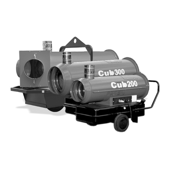
- Page 1 Repair Manual Indirect-Fired Air Heater Cub 200 Cub 300 0179422en 1009...
- Page 2 This publication may be photocopied by the original purchaser of the machine. Any other type of reproduction is prohibited without express written permission from Wacker Neuson Corporation. Any type of reproduction or distribution not authorized by Wacker Neuson Corporation represents an infringement of valid copyrights. Violators will be prosecuted. Trademarks All trademarks referenced in this manual are the property of their respective owners.
- Page 3 The information contained in this manual is based on machines manufactured up until the time of publication. Wacker Neuson Corporation reserves the right to change any portion of this information without notice. Manufacturer’s...
- Page 4 Foreword Cub 200/300 ghi_tx001204gb.fm...
-
Page 5: Table Of Contents
Cub 200/300 Table of Contents Safety Information Signal Words Found in this Manual ............7 Safety Guidelines for Operating the Machine ........8 Safety Guidelines for Lifting the Machine ..........9 Safety Guidelines While Using Combustion Burners ......10 Safety Guidelines for Maintaining the Machine ........11 Operation Controls and Components .............. - Page 6 Checking the Air Pressure Switch ............48 Checking the Fuel Solenoid ..............51 Checking the Flame Head ..............54 Checking the Fuel Flow from the Nozzle ..........55 Checking the Fuel Lines ..............57 6.10 Checking the Fuel Pump Adapter ............58 Schematic Cub 200/Cub 300 Schematic ..............59 ghi_br0179422en_001TOC.fm...
-
Page 7: Safety Information
Cub 200/300 Safety Information Safety Information Signal Words Found in this Manual This is the safety alert symbol. It is used to alert you to potential personal hazards. Obey all safety messages that follow this symbol. DANGER DANGER indicates a hazardous situation which, if not avoided, will result in death or serious injury. -
Page 8: Safety Guidelines For Operating The Machine
Familiarize yourself with the location and proper use of all controls and safety devices. Contact Wacker Neuson Corporation for additional training if necessary. When operating this machine: Do not allow improperly trained people to operate the machine. People operating the machine must be familiar with the potential risks and hazards associated with it. -
Page 9: Safety Guidelines For Lifting The Machine
Cub 200/300 Safety Information When operating the machine: Do not connect ductwork between the exhaust outlet port and the supply air inlet port. Never operate the machine in areas that contain flammable objects, fuels, or products that produce flammable vapors. -
Page 10: Safety Guidelines While Using Combustion Burners
Safety Information Cub 200/300 Safety Guidelines While Using Combustion Burners When using the machine: Clean up any spilled fuel immediately. Replace the fuel tank cap after refueling the machine. Refill the fuel tank in a well-ventilated area. Shut down the generator, if equipped, when refueling. -
Page 11: Safety Guidelines For Maintaining The Machine
Replace worn or damaged components. labels Use only spare parts recommended by Wacker Neuson Corporation. Replace all missing and hard-to-read labels. Replace or repair electrical components with components that are identical in rating and performance as the original component. -
Page 12: Operation
Operation Cub 200/300 Operation Controls and Components Component Component Fuel tank Air outlet Flue collar (vent) Burner access panel Handle (and base) Control panel Blower Fuel oil filter Lifting device Duct adapter ghi_tx001205gb.fm... -
Page 13: Control Panel
Cub 200/300 Operation Control Panel Component Function Remote thermostat The remote thermostat receptacle (shown with protective receptacle cap installed) is used for connecting an optional remote thermostat. Burner fault lamp and reset The dual function burner fault lamp and reset button: button (dual function) •... -
Page 14: Starting/Stopping The Machine
Operation Cub 200/300 Starting/Stopping the Machine If not using the remote thermostat Turning ON 1. Move the power switch (c) to the ON “I” position. The blower will turn on immediately. The burner will go through a prepurge cycle and then ignite. - Page 15 Cub 200/300 Operation Notes ghi_tx001205gb.fm...
-
Page 16: Burner Setup
Burner Setup Cub 200/300 Burner Setup Control Board Sequence of Operation Periods The burner controller has several periods it sequences through during normal operation. These periods are described below. Period Action or Function Prepurge (T1) As soon as the control switch (SW) is turned ON, the prepurge period begins. - Page 17 Cub 200/300 Burner Setup Period Action or Function Operation (T3) After the ignition period, the operation period begins. It will last as long as there is flame or until the heater is turned off. During this period: The fan runs.
-
Page 18: Setting Up The Burner
Winter-blend diesel Note: The burner on this machine was calibrated by test-firing for correct operation at Wacker Neuson Corporation located 180 m (600 ft.) above sea level using #2 diesel fuel combined with an anti-gelling additive. Tools required The following tools are required to adjust the burner:... - Page 19 Cub 200/300 Burner Setup Continued from the previous page. When Adjust the burner: Before operating the machine at elevations 305 m (1,000 ft) above or below the location of where the last adjustments were made Before starting at a new job site...
- Page 20 Burner Setup Cub 200/300 Continued from the previous page. 8. Analyze the combustion. Follow the combustion analyzer manufacturer’s instructions and the general guidelines below. Use the access hole in the exhaust stack. Take several samples as the heater warms. Take the final sample just before the heater reaches 71°C (160°F).
-
Page 21: Removing And Installing The Burner Assembly
Cub 200/300 Burner Setup Removing and Installing the Burner Assembly Background Before performing any maintenance on the burner assembly, it must be removed from the machine. Removal To remove or install the burner assembly perform the following procedure: 1. Shut down the machine and allow it to cool. -
Page 22: Checking And Adjusting The Burner Electrodes
Burner Setup Cub 200/300 Checking and Adjusting the Burner Electrodes Requirements Burner assembly removed Background Inspect the electrodes for the following: Wear Be sure to inspect the ends of the electrodes for pitting. Replace any worn elec- trodes. Straightness Replace any bent or broken electrodes. -
Page 23: Checking And Replacing The Burner Nozzle
Cub 200/300 Burner Setup Checking and Replacing the Burner Nozzle Requirements Burner assembly removed Removal Perform the procedure to remove the nozzle. 1. Remove the burner assembly. See topic Removing and Installing the Burner Assembly. 2. Place an adjustable wrench on the large fitting (1) on the nozzle base (3). -
Page 24: Setting The Air Band
Burner Setup Cub 200/300 Setting the Air Band Requirements Machine shut down Power disconnected Procedure Perform the procedure below to set the air band. 1. Shut down the machine and allow it to cool. 2. Disconnect the power cord from the power source. -
Page 25: Checking And Adjusting The Fuel Pressure
Cub 200/300 Burner Setup Checking and Adjusting the Fuel Pressure Requirements Pressure gauge British Parallel Thread (BPT) adapter Procedure To check and/or adjust the fuel pressure, carry out the following procedure: 1. Shut down the machine and allow it to cool. - Page 26 Burner Setup Cub 200/300 Continued from the previous page. 9. Adjust the fuel pressure, if necessary, using the adjusting screw (e). NOTICE: Do not adjust the fuel pressure outside of the parameters listed in the Technical Data charts. 10.Restart the machine and check the gauge.
-
Page 27: Troubleshooting Basics
Cub 200/300 Troubleshooting Basics Troubleshooting Basics Where to Begin Procedure Perform the procedure below to determine where to begin. 1. Connect the power cord to a 120 VAC power supply. 2. Turn the machine on. Then The blower runs, the problem is with the burner system. -
Page 28: Troubleshooting The Blower
Troubleshooting the Blower Cub 200/300 Troubleshooting the Blower Best practice The best practice when troubleshooting this system is to: 1. Isolate and check each component of this system individually. 2. When a malfunctioning component is found, repair or replace it. -
Page 29: Checking The Fuse
Cub 200/300 Troubleshooting the Blower Checking the Fuse Requirements 120V power source Procedure Perform the procedure below to check the fuse. 1. Connect the power cord to a 120 VAC power supply. 2. Observe the green light (x). Does the green light illuminate? - Page 30 Troubleshooting the Blower Cub 200/300 Continued from the previous page. 5. Remove the cover (b) from the control panel. 6. Locate the fuse (c) and check its condition. 7. Replace the fuse if it is blown with a fuse of the same size and rating.
-
Page 31: Checking Power To/From The Control Board
Cub 200/300 Troubleshooting the Blower Checking Power to/from the Control Board Requirements 120 VAC power source Multimeter Machine’s fuse is OK Procedure Perform the procedure below to check power to/from the control board. WARNING Electric shock hazard. High voltage exists inside the control panel when the power cord is plugged into a power supply. - Page 32 Troubleshooting the Blower Cub 200/300 Continued from the previous page. 5. Measure the voltage between terminal M8 and terminal M11 on the control board. Is 108–132 VAC measured? Yes ____ No ____ Continue. Disconnect the power supply. Check the function of the ON-OFF switch and the wiring to the ON-OFF switch.
-
Page 33: Checking The On-Off Switch
Cub 200/300 Troubleshooting the Blower Checking the ON-OFF Switch Requirements Electric power disconnected from the machine Multimeter Procedure Perform the procedure below to check the ON-OFF switch. 1. Disconnect the power cord from the power supply. WARNING Electric shock hazard. High voltage exists inside the control panel when the power cord is plugged into a power supply. - Page 34 Troubleshooting the Blower Cub 200/300 Continued from the previous page. 6. Check that there is continuity between the two terminals where the black and brown wires are connected. There should be continuity when in the ON position and no continuity in the OFF position.
-
Page 35: Checking The Capacitor
Cub 200/300 Troubleshooting the Blower Checking the Capacitor Requirements Power disconnected Multimeter Procedure Perform the procedure below to check the capacitor. 1. Disconnect the power cord from the electric power supply. WARNING Electric shock hazard. High voltage exists inside the machine when the power cord is plugged into a power supply. - Page 36 Troubleshooting the Blower Cub 200/300 Continued from the previous page. Does the capacitor measure 45–55 µF? Yes ____ No ____ Continue. The capacitor has failed; replace it. 6. If the capacitor checks OK but the motor still hums, the problem is with the wiring from the motor to the capacitor.
-
Page 37: Troubleshooting The Burner
Cub 200/300 Troubleshooting the Burner Troubleshooting the Burner Background The two sources of flame problems are: Fuel Ignition Note: Make sure the blower runs before troubleshooting burner problems. If the blower does not run, the burner will not fire. See topic Troubleshooting the Blower. - Page 38 Troubleshooting the Burner Cub 200/300 Continued from the previous page. Fuel problems For fuel system problems, check the following items in the sequence listed. Order Component See topic Fuel tank/supply Fuel filter Air band setting Fuel filter heater Fuel pressure Depending on the results of the fuel pressure, continue with the appropriate sequence below.
-
Page 39: Checking The Ignition Transformer
Cub 200/300 Troubleshooting the Burner Checking the Ignition Transformer Requirements Fuel solenoid disconnected Procedure Perform the procedure below to check the ignition transformer. 1. Begin this procedure with the power supply disconnected. 2. Open the access panel (a). 3. Locate the fuel solenoid (b) and disconnect it. - Page 40 Troubleshooting the Burner Cub 200/300 Continued from the previous page. 7. Turn the machine off. 8. Remove the screws (c) that hold the control panel and pull the control panel from the machine. 9. Remove the cover (d) from the control.
- Page 41 Cub 200/300 Troubleshooting the Burner Continued from the previous page. 12.Turn the machine off. 13.Check the condition of the ignition wires (g) between the transformer (h) and the flame head (i). If the ignition wires are damaged, replace them. 14.Check the resistance of the ignition wires. They should measure approximately 1000 ohms.
-
Page 42: Checking The Cad Cell
Troubleshooting the Burner Cub 200/300 Checking the Cad Cell Requirements Power disconnected from the machine Multimeter Procedure Perform the procedure below to check the cad cell. 1. Disconnect the power cord from the power supply. 2. Open the access panel (a). - Page 43 Cub 200/300 Troubleshooting the Burner Continued from the previous page. 6. Disconnect the light green wires (e) from terminals M5 and M6 of the burner controller. 7. Measure the resistance of the cad cell by measuring across the light green wires.
-
Page 44: Checking The Fuel Filter Heater
Troubleshooting the Burner Cub 200/300 Checking the Fuel Filter Heater Requirements Multimeter Electric power disconnected from the machine Procedure Perform the procedure below to check the fuel filter heater. 1. Turn on the machine. 2. Wait 10–15 minutes, then feel the outside of the fuel filter canister (c). - Page 45 Cub 200/300 Troubleshooting the Burner Continued from the previous page. 6. Check that the fuel heater is connected to terminals M7 and M12 of the control board. WARNING Electric shock hazard. High voltage exists inside the control panel when the power cord is plugged into a power supply.
-
Page 46: Checking Output Voltage From The Control Board
Troubleshooting the Burner Cub 200/300 Checking Output Voltage from the Control Board Requirements Multimeter Procedure Perform the procedure below to check output voltage from the control board for the fuel system. 1. Start this procedure with the machine disconnected from the power supply. - Page 47 Cub 200/300 Troubleshooting the Burner Continued from the previous page. 6. Measure the voltage between terminal M13 and terminal M18. To do so, you must wait through the 10-second prepurge cycle. Note: The voltage will only be present for approximately 1 second if the flame is not established.
-
Page 48: Checking The Air Pressure Switch
Troubleshooting the Burner Cub 200/300 Checking the Air Pressure Switch Requirements Multimeter Procedure Perform the procedure below to check the air pressure switch. 1. Start this procedure with the machine disconnected from the power supply. 2. Remove the side access panel (a) from the machine. - Page 49 Cub 200/300 Troubleshooting the Burner Continued from the previous page. Is 108–132 VAC measured? Yes ____ No ____ Continue. The wiring between the control board and the air pressure switch has failed. Shut down the machine and check this wiring.
- Page 50 Troubleshooting the Burner Cub 200/300 Continued from the previous page. 10.With the machine on, check the continuity between the same terminals of the air pressure switch. Is there continuity? Yes ____ No ____ The air pressure switch is OK. The air pressure switch has failed. Shut down the machine and replace the air pressure switch.
-
Page 51: Checking The Fuel Solenoid
Cub 200/300 Troubleshooting the Burner Checking the Fuel Solenoid Requirements Multimeter Air pressure switch checks OK Procedure Perform the procedure below to check the fuel solenoid. 1. Turn the machine off. 2. Open the access panel (a). 3. Locate the fuel solenoid (b) and disconnect it. - Page 52 Troubleshooting the Burner Cub 200/300 Continued from the previous page. 4. Turn the machine on. If the machine is in a fault condition, press the RESET (c) button on the control panel. 5. Measure the voltage at the connector (d). To do so, you must wait through the 10-second prepurge cycle.
- Page 53 Cub 200/300 Troubleshooting the Burner Continued from the previous page. 7. Measure the resistance across the coil of the solenoid as shown. Is 600–700 ohms measured? Yes ____ No ____ The fuel solenoid is OK. The fuel solenoid has failed; replace it.
-
Page 54: Checking The Flame Head
Troubleshooting the Burner Cub 200/300 Checking the Flame Head Requirements Power disconnected Hand tools Procedure Perform the procedure below to check the flame head. 1. Disconnect the power cord from the power supply. WARNING Electric shock hazard. High voltage exists inside the machine when the power cord is plugged into a power supply. -
Page 55: Checking The Fuel Flow From The Nozzle
Cub 200/300 Troubleshooting the Burner Checking the Fuel Flow from the Nozzle Requirements Container to catch fuel (5 gallon bucket) Procedure Perform the procedure below to check the fuel flow from the nozzle. 1. Disconnect the power cord from the power supply. - Page 56 Troubleshooting the Burner Cub 200/300 Continued from the previous page. 6. Connect the machine to the power supply. WARNING Fire hazard. The fuel may ignite if there is an ignition source nearby. Fire can cause severe injury or death. Continue this procedure only when all sources of ignition have been removed from the proximity of the machine.
-
Page 57: Checking The Fuel Lines
Cub 200/300 Troubleshooting the Burner Checking the Fuel Lines Requirements Machine turned off Power supply disconnected Procedure Perform the following procedure to check the fuel lines. 1. Turn the machine off. 2. Inspect the fuel lines (a) for leakage and loose fittings. -
Page 58: Checking The Fuel Pump Adapter
Troubleshooting the Burner Cub 200/300 6.10 Checking the Fuel Pump Adapter Requirements Machine turned off Power supply disconnected Procedure Perform the following procedure to check the fuel pump adapter. 1. Turn the machine off. 2. Open the access panel (a). -
Page 59: Schematic
Cub 200/300 Schematic Schematic Cub 200/Cub 300 Schematic ghi_tx001210gb.fm... - Page 60 175°C (350°F). If a screw or bolt is hard to remove, heat it using a small propane torch to break down the sealant. When applying sealants, follow instructions on container. The sealants listed are recommended for use on Wacker Neuson equipment. TYPE PART NO. –...
- Page 61 175°C (350°F). If a screw or bolt is hard to remove, heat it using a small propane torch to break down the sealant. When applying sealants, follow instructions on container. The sealants listed are recommended for use on Wacker Neuson equipment. TYPE PART NO. –...
- Page 62 Torque Values Torque Values Metric Fasteners (DIN) TORQUE VALUES (Based on Bolt Size and Hardness) WRENCH SIZE 10.9 12.9 Size ft.lb. ft.lb. ft.lb. Metric Inch Metric Inch 7/32 – 9/32 – 5/16 – – – – 11/16 – – – 15/16 –...
- Page 63 Torque Values Torque Values (continued) Inch Fasteners (SAE) Size ft.lb. ft.lb. ft.lb. Metric Inch Metric Inch No.4 – 3/32 No.6 5/16 – 7/64 No.8 11/32 – 9/64 No.10 – – 5/32 – 7/16 – 3/32 5/16 – – 9/16 – 5/16 7/16 –...
- Page 64 Ground Heaters, Inc. · 1271 Judson Road · Spring Lake, MI 49456 · Tel: (231) 799-9600 · Fax: (231) 799-9500 · Tel: (877) 799-9600...
Need help?
Do you have a question about the CUB 200 and is the answer not in the manual?
Questions and answers