
Related Manuals for Wacker Neuson HI 110HD D


Summary of Contents for Wacker Neuson HI 110HD D
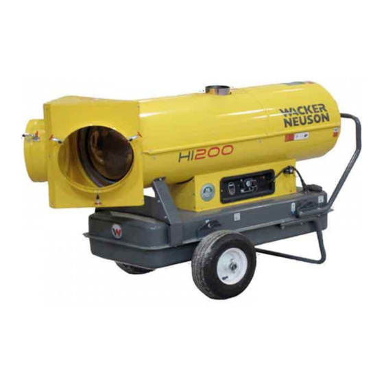
- Page 1 Operator’s Manual Indirect-Fired Air Heaters HI 110D / HI 110HD D HI 200D / HI 200HD D HI 300D / HI 300HD D 5000192822 0614...
- Page 2 Wacker Neuson Production Americas LLC. Any type of reproduction or distribution not authorized by Wacker Neuson Production Americas LLC represents an infringement of valid copyrights. Violators will be prosecuted.
-
Page 3: Foreword
REGULATIONS OF THE AUTHORITIES HAVING JURISDICTION. SAVE THESE INSTRUCTIONS—This manual contains important instructions for the machine models below. These instructions have been written expressly by Wacker Neuson Production Americas LLC and must be followed during installation, operation, and maintenance of the machines. Machines... - Page 4 Refer to the separate Repair Manual for detailed instructions on servicing and repairing the machine. If you are missing any of these documents, please contact Wacker Neuson to order a replacement or visit www.wackerneuson.com. When ordering parts or requesting service information, be prepared to provide the machine model number, item number, revision number, and serial number.
-
Page 5: Table Of Contents
HI 110 / 200 / 300 Table of Contents Foreword Safety Information Signal Words Found in this Manual ............7 Machine Description and Intended Use ..........8 Operating Safety .................. 9 Safety Guidelines for Operating Combustion Burners ....... 10 Service Safety ..................11 Labels Label Locations .................. - Page 6 Table of Contents HI 110 / 200 / 300 Burner Setup Removing the Access Panel ...............40 Removing and Installing the Burner Assembly ........41 Setting Up the Burner ................42 Checking the Oil Burner Electrodes ............44 Checking/Changing the Burner Nozzle ..........45 Adjusting the Fuel Pressure ..............46 Setting the Air Band ................47 Maintenance Periodic Maintenance Schedule ............48...
-
Page 7: Safety Information
HI 110 / 200 / 300 Safety Information Safety Information Signal Words Found in this Manual This manual contains DANGER, WARNING, CAUTION, NOTICE, and NOTE signal words which must be followed to reduce the possibility of personal injury, damage to the equipment, or improper service. This is the safety alert symbol. -
Page 8: Machine Description And Intended Use
To protect yourself and others, make sure you thoroughly read and understand the safety information presented in this manual before operating the machine. Optional Wacker Neuson Corporation offers many optional accessories for the machine. accessories These accessories include the following:... -
Page 9: Operating Safety
Familiarize yourself with the location and proper use of all controls and safety devices. Contact Wacker Neuson for additional training if necessary. When operating this machine: Do not allow improperly trained people to operate the machine. People operating the machine must be familiar with the potential risks and hazards associated with it. -
Page 10: Safety Guidelines For Operating Combustion Burners
Safety Information HI 110 / 200 / 300 Machine As a recommended installation practice, refer to the current issue of CSA B139, installation Installation Code for Oil Burning Equipment in Canada and NFPA 31 Standard for guidelines the Installation of Oil-Burning Equipment in the USA; Never operate the machine in immediate proximity to flammable materials. -
Page 11: Service Safety
Accessories, When using the machine: safety devices Use only accessories/attachments that are recommended by Wacker Neuson Corporation. modifications When using the machine: Never operate the machine if any safety devices or guards are missing or inoperative. - Page 12 Safety Information HI 110 / 200 / 300 Hearing protection Safety-toed footwear In addition, before servicing or maintaining the machine: Tie back long hair. Remove all jewelry (including rings). ghi_si000463gb.fm...
-
Page 13: Labels
HI 110 / 200 / 300 Labels Labels Label Locations HI 110 HI 200 wc_gr009251 ghi_si000464gb.fm... - Page 14 Labels HI 110 / 200 / 300 HI 300 D G H HI 300 HD wc_gr009252 ghi_si000464gb.fm...
-
Page 15: Label Meanings
HI 110 / 200 / 300 Labels Label Meanings WARNING Hot surface hazard! WARNING Entanglement hazard. Rotating machinery. Do not reach inside machine when engine is running. NOTICE Lifting point WARNING! Electric shock hazard. Disconnect power before servicing. Read Operator’s Manual. CAUTION This machine uses diesel fuel. - Page 16 Labels HI 110 / 200 / 300 DANGER Using a heater indoors can kill you in minutes. Heater exhaust contains carbon monoxide. This is a poison you cannot see or smell. During indoor operation, vent exhaust gas outdoors. Refer to Operator's Manual.
- Page 17 HI 110 / 200 / 300 Labels WARNING Licensed gas technician required. Natural gas / liquid propane burner setup and installation, fuel supply connection, test firing, and burner adjustment MUST be performed by a LICENSED professional gas technician and must conform to the requirements of all relevant local, state, provincial, and Federal authorities.
- Page 18 Labels HI 110 / 200 / 300 — Fork lift pocket ghi_si000464gb.fm...
-
Page 19: Lifting And Transporting
HI 110 / 200 / 300 Lifting and Transporting Lifting and Transporting Lifting and Transporting the Machine Requirements Transport vehicle capable of carrying 1000 lbs (454 kg) Crane or lift capable of carrying 1000 lbs (454 kg) Background NOTICE: These machines are NOT designed to be towed with any vehicle. WARNING Crushing hazard. -
Page 20: Operation
Operation HI 110 / 200 / 300 Operation Installing the Lift Brackets (if equipped) Before attempting to lift the machine, the lift brackets must be installed. 1. Remove the machine from the crate. 2. Intstall the four lift brackets as shown using the supplied bolts and washers. ghi_tx001447gb.fm... -
Page 21: Installing The Wheels And Handle
HI 110 / 200 / 300 Operation Installing the Wheels and Handle Overview The axle, wheels, handle, and stand are shipped loose with the machine and must be assembled before operation. There are pre-drilled holes for all of the components to be assembled. Bolts, washers, and nuts are provided. -
Page 22: Controls And Service Locations
Operation HI 110 / 200 / 300 Controls and Service Locations HI 110D HI 200 wc_gr009253 ghi_tx001447gb.fm... - Page 23 HI 110 / 200 / 300 Operation HI 300 HI 300 HD 009254 Machine components Description Description Exhaust flue Air inlet and fan guard Control panel Access panel Manual transport handle Fuel filter Fuel fill location Manual holder (Only on HI 200 HD and HI 300 HD models) Lift brackets (if equipped) —...
-
Page 24: Control Panel
Operation HI 110 / 200 / 300 Control Panel Control panel components Description Description Burner fault lamp and reset Power indicator button (dual function) Mode switch (on-off-on) Power cord See topic Starting the Machine. Thermostat receptacle — — Symbols and meanings Symbol Meaning/function... -
Page 25: Recommended Fuels And Fuel Blending Guide
HI 110 / 200 / 300 Operation Recommended Fuels and Fuel Blending Guide Low ambient temperatures cause diesel fuels to gel. Gelled fuels will cause burner ignition failure and/or burner fuel pump damage. Always use the proper fuel for the conditions. -
Page 26: Inspecting The Fuel Hose
Operation HI 110 / 200 / 300 Inspecting the Fuel Hose When Visually inspect the fuel hose assembly each time before operating the heater. WARNING Fire and explosion hazards. A damaged hose may leak flammable fuel. Do not operate the heater if the hose has excessive abrasions, wear, or cuts. Replacement Replace a damaged hose assembly with an equivalent as specified on the hose... -
Page 27: Positioning The Machine
HI 110 / 200 / 300 Operation Positioning the Machine DANGER Exhaust gas from the burner contains carbon monoxide, a deadly poison. Exposure to carbon monoxide can kill you in minutes. Never run the machine indoors or in an enclosed area unless the machine is vented properly according to local and national codes. -
Page 28: Suggested Venting
Duct Do not use B-vent exhaust pipes to vent an oil burning machine. Contact requirements Wacker Neuson Product Support for recommended alternatives. Check local codes for appropriate vent piping materials. Machine Position the machine in a manner that avoids excessive vent bends (elbows), setup and long horizontal runs. - Page 29 HI 110 / 200 / 300 Operation Note: The above venting diagram shows suggested venting layouts only. Consult all appropriate governing bodies or local contractor for venting and fresh air requirements. ghi_tx001447gb.fm...
-
Page 30: Installing The Heater Duct
Operation HI 110 / 200 / 300 Installing the Heater Duct Overview Optional ducts can be connected to the air outlet. This allows warm air to be evenly distributed throughout the heating area. NOTICE: When using ducts, observe the static air pressure limits specified in Technical Data. -
Page 31: Flex Ducting Options
HI 110 / 200 / 300 Operation 4.10 Flex Ducting Options Refer to the chart below for the maximum allowable return and supply duct lengths for your machine. NOTICE: Do not exceed the maximum total lengths specified in the chart. Exceeding these lengths, or blocking any of the duct openings, constricts the air flow through the machine and may cause a high-temperature shut-down fault. -
Page 32: Connecting Power To The Machine
Operation HI 110 / 200 / 300 4.11 Connecting Power to the Machine Requirements Power source (115VAC) Machine properly positioned Operation mode switch in the OFF (0) position WARNING Fire hazard and electric shock hazard. The use of under-sized extension cords can lead to fire and electric shock. -
Page 33: Pre-Starting Checks
HI 110 / 200 / 300 Operation 4.12 Pre-Starting Checks Requirements Machine properly positioned Power connected to the machine Checks Before starting the machine, check the following items: Item Task Fuel sight gauge (if equipped) Check that the fuel tank is full (if applicable). Fuel tank cap Check that the fuel tank cap (if applicable) is secure. -
Page 34: Starting The Machine
Operation HI 110 / 200 / 300 4.13 Starting the Machine Requirements Machine properly positioned Power connected Pre-Starting Checks completed Procedure To start the machine, follow the procedure below. 1. Select an operation mode. a. Continuous heat mode (I) b. Thermostat mode (II) wc_gr007558 Operational The following sequence of events will occur. -
Page 35: Starting The Machine In Extremely Cold Weather
HI 110 / 200 / 300 Operation 4.14 Starting the Machine in Extremely Cold Weather Background In temperatures below 32°F (0°C), it may be necessary to preheat the fuel inside the fuel filter canister. The fuel filter canister is equipped with a low-wattage heating element specially designed for this purpose. -
Page 36: Stopping The Machine
Operation HI 110 / 200 / 300 4.15 Stopping the Machine Procedure Follow the procedure below to stop the machine. WARNING Electric shock hazard. Electric power is still active at the blower even when the machine is turned OFF. Remove all electric power to the machine before servicing the machine. 1. -
Page 37: Burner Faults
HI 110 / 200 / 300 Operation 4.16 Burner Faults The burner fault lamp / reset button (a) is illuminated while the machine is operating. The lamp is green during normal operation. Burner fault A burner fault occurs if the burner does not start after two failed attempts to start or restart upon shutdown. -
Page 38: Installing And Using The Remote Thermostat
Edison plug style connection for use with commonly available thermostats. This adapter can be purchased using Wacker Neuson part #5200007098. NOTICE: The thermostat adapter is designed for use ONLY with a thermostat. To avoid damaging the machine, do not plug any other equipment into the thermostat adapter. -
Page 39: Accessories
Accessories Accessories Available Accessories Introduction Wacker Neuson Corporation offers many optional accessories for this machine. These accessories are described below. Contact your local Wacker Neuson dealer or visit www.wackerneuson.com for ordering information. Item Description/Purpose Remote thermostat Allows the user to remotely control the target... -
Page 40: Burner Setup
Burner Setup HI 110 / 200 / 300 Burner Setup Removing the Access Panel Requirements Machine shut down and cooled Machine properly positioned CAUTION Hot surface hazard. The machine surfaces may be hot. Allow the machine to cool for a minimum of ten minutes before touching it. Overview Your machine is equipped with a removable access panel. -
Page 41: Removing And Installing The Burner Assembly
HI 110 / 200 / 300 Burner Setup Removing and Installing the Burner Assembly Requirements Machine shut down and cooled Machine properly positioned CAUTION Hot surface hazard. The machine surfaces may be hot. Allow the machine to cool for a minimum of ten minutes before touching it. Procedure Before performing any maintenance on the burner assembly, it must be removed from the machine. -
Page 42: Setting Up The Burner
Burner Setup HI 110 / 200 / 300 Setting Up the Burner Factory settings Machine Nozzle size Fuel pressure Air band setting Diesel Winter blend HI 110 D 0.55 x 80W HI 110 HD D 0.55 x 80W HI 200 D 1.10 x 80W 12.5 HI 200 HD D... - Page 43 HI 110 / 200 / 300 Burner Setup 7. Conduct a smoke spot test. Follow the smoke spot tester manufacturer’s instructions and the general guidelines below. HI Heater ghi_gr007395 Use the access hole in the exhaust stack. Several samples should be taken as the heater warms. The final sample should be taken just before the heater reaches 71°C (160°F).
-
Page 44: Checking The Oil Burner Electrodes
Refer to the table below to determine the condition of the electrode tips. wc_gr007619 Condition Task None; ok as-is None; ok as-is Replace The electrodes should be replaced if they are worn or damaged. Contact your Wacker Neuson dealer for replacement electrodes. ghi_tx001449gb.fm... -
Page 45: Checking/Changing The Burner Nozzle
HI 110 / 200 / 300 Burner Setup Checking/Changing the Burner Nozzle Prerequisites Machine shut down and cool to the touch Machine properly positioned CAUTION Hot surface hazard. The machine surfaces may be hot. Allow the machine to cool for a minimum of ten minutes before touching it. When Replace the burner nozzle annually, or if it is damaged. -
Page 46: Adjusting The Fuel Pressure
Burner Setup HI 110 / 200 / 300 Adjusting the Fuel Pressure Requirements Machine shut down and cool to the touch Power disconnected Fuel pressure gauge Background The information below will show you how to check the fuel pressure on your machine. -
Page 47: Setting The Air Band
HI 110 / 200 / 300 Burner Setup Adjusting fuel 8. Adjust the fuel pressure if necessary using the adjusting screw (e) and re-check pressure the settings. Repeat steps 4–6 to re-check the settings. NOTICE: Do not adjust the fuel pressure to a setting outside the safe operational parameters. -
Page 48: Maintenance
Maintenance HI 110 / 200 / 300 Maintenance Periodic Maintenance Schedule Interval* (hours of service) Daily 2 Weeks 6 Months Yearly Task (50) (1000) (1200) Inspect the heater. Inspect the hose assembly. Check fuel level and pressure. Clean the machine. Clean the fuel filter. -
Page 49: Inspecting The Heat Exchanger
HI 110 / 200 / 300 Maintenance Inspecting the Heat Exchanger Introduction The heat exchanger consists of the combustion chamber and an outer shell. As intake air flows over the hot combustion chamber, it collects heat. The heated intake air is then blown out of the supply ducts. Reasons for A cracked or damaged heat exchanger is hazardous! Poisonous carbon monoxide inspection... - Page 50 Maintenance HI 110 / 200 / 300 Continued from the previous page. Access Follow the procedure below to access the heat exchanger. procedure 1. Remove the access panel (a). (See Removing the Access Panel.) wc_gr008456 2. Loosen the three nuts (b) securing the burner tube assembly (c). Rotate and remove the burner tube assembly.
- Page 51 HI 110 / 200 / 300 Maintenance Continued from the previous page. Inspection Follow the procedure below to inspect the heat exchanger. procedure 1. Using a strong light and inspection mirror, inspect the outer shell of the combustion chamber for cracks or separations. 2.
-
Page 52: Changing The Fuel Heater Filter
Maintenance HI 110 / 200 / 300 Changing the Fuel Heater Filter Prerequisites Machine shut down Power disconnected Burner cool CAUTION Hot surface hazard. The external surface of the fuel filter canister may be hot. Allow the machine to cool before servicing. WARNING Hot fluids. -
Page 53: Inspecting And Cleaning The Cadmium (Cad) Cell
HI 110 / 200 / 300 Maintenance Inspecting and Cleaning the Cadmium (CAD) Cell Prerequisites Machine shut down and cool to the touch Machine properly positioned CAUTION Hot surface hazard. The machine surfaces may be hot. Allow the machine to cool for a minimum of ten minutes before touching it. When Inspect and clean the CAD cell as needed, or while performing other scheduled maintenance procedures. -
Page 54: Cleaning The Fan Blades And Motor
Maintenance HI 110 / 200 / 300 Cleaning the Fan Blades and Motor Prerequisites Machine shut down and cool to the touch Power source disconnected WARNING Electric shock hazard. Electric power is still active at the blower even when the machine is turned OFF. -
Page 55: Cleaning The Interior Shell
HI 110 / 200 / 300 Maintenance 3. Inspect and, if necessary, clean the motor (m) using compressed air. 4. Clean the fan blades using a stiff brush. 5. Reinstall the internal access panel. 6. Reinstall the fan guard. Cleaning the Interior Shell Prerequisites Machine shut down and cool to the touch Power source disconnected... -
Page 56: Inspecting The Flame Head
Maintenance HI 110 / 200 / 300 Inspecting the Flame Head Requirements Machine shut down and cool to the touch Machine properly positioned CAUTION Hot surface hazard. The machine surfaces may be hot. Allow the machine to cool for a minimum of ten minutes before touching it. When Inspect the flame head prior to the first seasonal use, during regular maintenance, and as needed. -
Page 57: Inspecting The Electrical Connections
HI 110 / 200 / 300 Maintenance Inspecting the Electrical Connections After disconnecting the power cord, check all electrical connections for the following: Proper connections. Be sure that all connections are complete and tight. Corrosion. Clean or replace if necessary. Damaged wires/connectors. -
Page 58: Cleaning The Machine
Maintenance HI 110 / 200 / 300 Cleaning the Machine Requirements Machine shut down Machine cool General Clean the following areas to ensure proper operation. cleaning Item Method/task Burner Remove all dirt and debris. Ensure that the air intake area is unobstructed. -
Page 59: Basic Troubleshooting
Note: The following symptoms and remedies are some of the more common issues that have arisen during the history of these machines. These do not repre- sent all the possibilities. If you need advanced troubleshooting assistance, please contact Wacker Neuson Product Support. Symptom Possible Causes... -
Page 60: Technical Data
Technical Data HI 110 / 200 / 300 Technical Data Machine Model HI 110D HI 200D HI 200HD D HI 110HD D Units Heat input BTU/hr 112,141 204,873 Heat output BTU/hr 92,516 173,117 Fuel consumption L (gal)/hr 3.1 (0.81) 5.6 (1.48) Efficiency 82.5... -
Page 61: Dimensions - Hi110D, Hi110Hd D
HI 110 / 200 / 300 Technical Data Model HI 300D HI 300HD D Units Heat input BTU/hr 293,982 293,982 Heat output BTU/hr 245,475 245,475 Fuel consumption L (gal)/hr 8 (2.12) 8 (2.12) Efficiency 83.5 83.5 Noise level at 1 m dB (A) Power requirement VAC/Hz... -
Page 62: Dimensions - Hi200D, Hi200Hd D
Technical Data HI 110 / 200 / 300 Dimensions - HI200D, HI200HD D in. (mm) 38.6 (983) 65.4 (1661) 30 (762) wc_gr012069 Dimensions - HI300D, HI300HD D in. (mm) 50 (1270) 69 (1740) 30 (762) wc_gr012070 in. (mm) 52 (1321) 84 (2134) 34 (864) wc_gr012071... - Page 63 HI 110 / 200 / 300 Technical Data wc_td000400gb.fm...
-
Page 64: Schematics
Schematics HI 110 / 200 / 300 10 Schematics 10.1 Electrical Schematic - HI 110 D, HI 110 HDD TGRD91 CSA 120V wc_gr012018 Description Description Fuse Control switch Overheat thermostat Room thermostat plug Solenoid valve Control box CAD cell Air pressure switch Capacitor Heated fuel filter (optional) Fan motor... -
Page 65: Electrical Schematic - Hi 200 D
HI 110 / 200 / 300 Schematics 10.2 Electrical Schematic - HI 200 D wc_gr012019 Description Description Fuse Room thermostat plug High voltage transformer Relay Overheat thermostat Control box Solenoid valve Heated fuel filter CAD cell Air pressure switch Capacitor Reset switch / lockout indicator Fan motor Resistance heater coil*... -
Page 66: Electrical Schematic - Hi 200 Hdd
Schematics HI 110 / 200 / 300 10.3 Electrical Schematic - HI 200 HDD wc_gr012025 Description Description Fuse Room thermostat plug High voltage transformer Relay Overheat thermostat Control box Solenoid valve Heated fuel filter CAD cell Air pressure switch Capacitor Reset switch / lockout indicator Fan motor Resistance heater coil*... -
Page 67: Electrical Schematic - Hi 300 D
HI 110 / 200 / 300 Schematics 10.4 Electrical Schematic - HI 300 D wc_gr012020 Description Description Fuse Room thermostat plug High voltage transformer Relay Overheat thermostat Control box Solenoid valve Heated fuel filter CAD cell Air pressure switch Capacitor Reset switch / lockout indicator Fan motor Resistance heater coil*... -
Page 68: Electrical Schematic - Hi 300 Hdd
Schematics HI 110 / 200 / 300 10.5 Electrical Schematic - HI 300 HDD Description Description Fuse Room thermostat plug High voltage transformer Relay Overheat thermostat Control box Solenoid valve Heated fuel filter CAD cell Air pressure switch Capacitor Reset switch / lockout indicator Fan motor Resistance heater coil* Electric pilot lamp... - Page 70 Tel. : (262) 255-0500 Fax: (262) 255-0550 Tel.: (800) 770-0957 Wacker Neuson Limited - Room 1701–03 & 1717–20, 17/F. Tower 1, Grand Century Place, 193 Prince Edward Road West, Mongkok, Kowloon, Hongkong. Tel: (852) 3605 5360, Fax: (852) 2758 0032...
Need help?
Do you have a question about the HI 110HD D and is the answer not in the manual?
Questions and answers