
Related Manuals for Wacker Neuson HI 400 HD G


Summary of Contents for Wacker Neuson HI 400 HD G
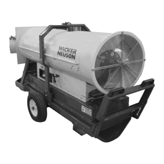
- Page 1 Operator’s Manual Indirect-Fired Air Heaters HI 400 HD D HI 400 HD G 5000192824 0615...
- Page 2 Wacker Neuson Production Americas LLC. Any type of reproduction or distribution not authorized by Wacker Neuson Production Americas LLC represents an infringement of valid copyrights. Violators will be prosecuted.
-
Page 3: Foreword
HI 400HD D / HD G Foreword Foreword This heater is designed and approved for use as a construction heater in accordance with Standard ANSI Z83.7–CSGA 2.14. CHECK WITH YOUR LOCAL FIRE SAFETY AUTHORITY IF YOU HAVE QUESTIONS ABOUT APPLICATIONS. Other standards govern the use of fuel gases and heat producing products in specific applications. - Page 4 Keep a copy of the Operator’s Manual with the machine at all times. Use the separate Parts Book supplied with the machine to order replacement parts. If you are missing either of these documents, please contact Wacker Neuson to order a replacement or visit www.wackerneuson.com. ghi_tx001460gb.fm...
- Page 5 Expectations This manual provides information and procedures to safely operate and main- tain the above Wacker Neuson model(s). For your own safety and to reduce information in the risk of injury, carefully read, understand, and observe all instructions this manual described in this manual.
- Page 6 Foreword HI 400HD D / HD G ghi_tx001460gb.fm...
-
Page 7: Table Of Contents
Safety Guidelines for Operating Combustion Burners ....... 16 Service Safety ..................17 Labels Label Locations - HI 400 HD D ............19 Label Locations - HI 400 HD G ............20 Label Meanings .................. 21 Lifting and Transporting Operation Preparing the Machine for First Use ........... 27 Installing the Axle and Wheels ............ - Page 8 Table of Contents HI 400HD D / HD G 4.22 Before Starting ..................47 4.23 Cold Weather Start-Up ................48 4.24 Starting the Machine (D models) ............49 4.25 Starting the Machine (G models) ............50 4.26 High and Low Voltage Protection (G Models) ........51 4.27 Stopping ....................52 4.28...
- Page 9 HI 400HD D / HD G Table of Contents 10 Schematics 10.1 HI 400HD D ..................80 10.2 Components ..................81 10.3 HI 400HD G (2014) ................82 10.4 Components (2014) ................83 10.5 HI 400HD G (2015) ................84 10.6 Components (2015) ................
- Page 10 Table of Contents HI 400HD D / HD G wc_bo5000192824_09TOC.fm...
-
Page 11: Safety Information
HI 400 Safety Information Safety Information Signal Words Used in this Manual This manual contains DANGER, WARNING, CAUTION, NOTICE, and NOTE signal words which must be followed to reduce the possibility of personal injury, damage to the equipment, or improper service. This is the safety alert symbol. -
Page 12: Machine Description And Intended Use
To protect yourself and others, make sure you thoroughly read and understand the safety information presented in this manual before operating the machine. Optional Wacker Neuson Corporation offers many optional accessories for the machine. accessories These accessories include the following: Remote thermostat Duct adapters (various sizes, available as kits, or individual ducts at 25 ft. -
Page 13: Operating Safety
To ensure safe operation of the machine: Do not operate the machine if any safety devices or guards are missing or inoperative. Do not modify or defeat the safety devices. Only use accessories or attachments that are approved by Wacker Neuson. ghi_si000468gb.fm... - Page 14 Safety Information HI 400 Safe When operating this machine: operating Remain aware of the machine’s moving parts. Keep hands, feet, and loose practices clothing away from the machine’s moving parts. When operating this machine: Do not operate a machine in need of repair. Personal Wear the following Personal Protective Equipment (PPE) while operating this Protective...
-
Page 15: Safety Guidelines For Gas-Fired Machines
HI 400 Safety Information Safety Guidelines for Gas-Fired Machines WARNING Gas leaks can cause explosions or fire. Follow the steps below if you smell gas. Open windows. Do not touch electrical switches. Extinguish open flames. Immediately call your gas supplier. WARNING Risk of explosion, fire, property damage, asphyxiation, death, or carbon monoxide poisoning. -
Page 16: Safety Guidelines For Operating Combustion Burners
Safety Information HI 400 Safety Guidelines for Operating Combustion Burners When using the machine: Clean up any spilled fuel immediately. Replace the fuel tank cap after refueling the machine. Refill the fuel tank in a well-ventilated area. Make sure you have proper certification or licensing required by the locality, state, or province in which the machine is being installed to work with natural gas or Liquid Petroleum (LP). -
Page 17: Service Safety
Machine When servicing or maintaining the machine: modifications Use only accessories/attachments that are approved by Wacker Neuson. When servicing or maintaining the machine: Do not defeat safety devices. Do not modify the machine without the express written approval of Wacker Neuson. - Page 18 Safety Information HI 400 Never use gasoline or other types of fuels or flammable solvents to clean the machine. Fumes from fuels and solvents can become explosive. Personal Wear the following Personal Protective Equipment (PPE) while servicing or Protective maintaining this machine: Equipment Close-fitting work clothes that do not hinder movement (PPE)
-
Page 19: Labels
HI 400HD D / HD G Labels Labels Label Locations - HI 400 HD D wc_gr011675 ghi_si000469gb.fm... -
Page 20: Label Locations - Hi 400 Hd G
Labels HI 400HD D / HD G Label Locations - HI 400 HD G wc_gr011676 ghi_si000469gb.fm... -
Page 21: Label Meanings
HI 400HD D / HD G Labels Label Meanings CAUTION This machine uses diesel fuel. NOTICE Lifting point Tie-down point. WARNING Hot surface WARNING Entanglement hazard. Rotating machinery. Do not reach inside machine when engine is running. WARNING Using a heater indoors can kill you in minutes. - Page 22 Labels HI 400HD D / HD G WARNING Electric shock hazard. Disconnect power before servicing. Read Operator’s Manual. WARNING Licensed gas technician required. Natural gas / liquid propane burner setup and installation, fuel supply connection, test firing, and burner adjustment MUST be performed by a LICENSED professional gas technician and must conform to the requirements of all relevant local, state,...
- Page 23 HI 400HD D / HD G Labels Gas shut-off valve Gas selector valve Propane Gas Position Natural Gas Position Lock valve in position after selection. Electrical grounding instructions. General usage warnings ghi_si000469gb.fm...
- Page 24 Labels HI 400HD D / HD G — Hose assembly specification — Gas type label Natural Gas Propane Gas WARNING Explosion and fire hazard. Read the Operator’s Manual for more information. If three consecutive attempts to reset the machine are unsuccessful, then troubleshoot the heating system for the root cause(s) of the lockout.
- Page 25 HI 400HD D / HD G Labels — Fork lift pocket ghi_si000469gb.fm...
-
Page 26: Lifting And Transporting
Lifting and Transporting HI 400HD D / HD G Lifting and Transporting Requirements Transport vehicle capable of carrying 1000 lbs (454 kg) Crane or lift capable of carrying 1000 lbs (454 kg) Background NOTICE: These machines are NOT designed to be towed with any vehicle. WARNING Crushing hazard. -
Page 27: Operation
1. Make sure all loose packaging materials have been removed from the machine. 2. Check the machine and its components for damage. If there is visible damage, do not operate the machine! Contact your Wacker Neuson dealer immediately for assistance. -
Page 28: Installing The Front Duct Adapter
Operation HI 400HD D / HD G Installing the Front Duct Adapter Overview The front duct adapter provided with your machine is shipped loose and must be installed before operating the machine. The thermostat probe must also be installed on the inside of the duct adapter during this procedure. Duct adapter Your machine is supplied with either a one-way, two-way, or three-way front duct varieties... -
Page 29: Blower Duct Heater Option
HI 400HD D / HD G Operation Blower Duct Heater Option Overview An optional 10 cm (4-inch) duct for preheating air drawn into the combustion blower can be installed. This accessory is recommended for use in extremely cold temperatures. Note: The installation instructions below are provided for your convenience. Refer to the complete instruction sheet packaged with the blower duct kit. -
Page 30: Installing The Rear Duct Adapter (Optional)
Operation HI 400HD D / HD G Installing the Rear Duct Adapter (Optional) Overview The optional rear duct adapter is shipped loose and must be installed before operating the machine. Procedure Follow the procedure below to install the rear duct adapter. 1. -
Page 31: Control / Component Locations
HI 400HD D / HD G Operation Control / Component Locations HI400HD G Machine components Description Description Exhaust flue Access cover Control panel Fuel filter (D units) Manual transport handle Gas train (G units only) Fuel fill location (D units only) Fork pockets Lift brackets Manual holder... -
Page 32: Adjusting The Handle Height
Operation HI 400HD D / HD G Adjusting the Handle Height Overview Your machine is equipped with a manual transport handle. The handle height can be adjusted to suit the operator’s preference. Procedure Follow the procedure below to adjust the handle height. 1. -
Page 33: Positioning The Machine
HI 400HD D / HD G Operation Positioning the Machine DANGER Carbon monoxide. Exhaust gas from the burner contains carbon monoxide, a deadly poison. Exposure to carbon monoxide can kill you in minutes. Never run the machine indoors or in an enclosed area unless the machine is vented properly according to local and national codes. -
Page 34: Electrical And Grounding
Operation HI 400HD D / HD G Electrical and Grounding WARNING Fire and electric shock hazards. The use of an innappropriate power supply, or undersized extension cords, can lead to fire and electric shock. Fire and electric shock can cause severe injury. Before use, ensure that the machine is properly connected to an appropriate power source and grounded per the requirements provided below. -
Page 35: Control Panel-Oil Burner (D Models)
HI 400HD D / HD G Operation 4.10 Control Panel—Oil Burner (D Models) RESET Control panel components Description Description Operating status indicator and Firing mode switch reset button (dual function) (High-fire or low-fire) Mode switch (on-off-on) Power indicator See topic Starting the Machine. Remote thermostat receptacle Power cord Symbols and... -
Page 36: Recommended Fuels And Fuel Blending Guide
Operation HI 400HD D / HD G 4.11 Recommended Fuels and Fuel Blending Guide Low ambient temperatures cause diesel fuels to gel. Gelled fuels will cause burner ignition failure and/or burner fuel pump damage. Always use the proper fuel for the conditions. -
Page 37: Control Panel-Gas Burner (G Models)
HI 400HD D / HD G Operation 4.13 Control Panel—Gas Burner (G Models) RESET Control panel components Description Description Operating status indicator and Power indicator reset button (dual function) Mode switch (on-off-on) Power cord See topic Starting the Machine. Remote thermostat receptacle Polarity indicator (illuminates when polarity of power supply is incorrect) -
Page 38: Gas Installation And Setup (G Models)
Operation HI 400HD D / HD G 4.14 Gas Installation and Setup (G models) WARNING Extreme explosion and fire hazards. Only a licensed, professional gas technician shall perform installation, fuel sup- ply connection, setup, adjustment, and testing of gas lines. Never use open flames to detect gas leaks. -
Page 39: Connecting The Gas Line (G Models)
HI 400HD D / HD G Operation 4.15 Connecting the Gas Line (G models) Overview The HI 400HD-G heater includes a 3/4 " NPT shutoff valve and inlet (a) on the gas safety valve / pressure regulator body. The gas supply line connects to the inlet. wc_gr007559 WARNING Extreme fire and explosion hazard! -
Page 40: Setting The Gas Selector Valve (G Models)
Operation HI 400HD D / HD G 4.16 Setting the Gas Selector Valve (G models) Overview Your machine is configured at the factory to operate on natural gas. The gas selector valve on the gas train allows you to convert the machine from natural gas to LP as job site conditions require. -
Page 41: Venting The Machine
Duct Do not use B-vent exhaust pipes to vent an oil burning machine. Contact requirements Wacker Neuson Product Support for recommended alternatives. Check local codes for appropriate vent piping materials. Machine Position the machine in a manner that avoids excessive vent bends (elbows), setup and long horizontal runs. - Page 42 Operation HI 400HD D / HD G Note: The above venting diagram shows suggested venting layouts only. Consult all appropriate governing bodies or local contractor for venting and fresh air requirements. ghi_tx001462gb.fm...
-
Page 43: Installing The Heater Duct
HI 400HD D / HD G Operation 4.18 Installing the Heater Duct Overview Optional ducts can be connected to the air outlet. This allows warm air to be evenly distributed throughout the heating area. NOTICE: When using ducts, observe the static air pressure limits specified in Technical Data. -
Page 44: Flex Ducting Options
Operation HI 400HD D / HD G 4.19 Flex Ducting Options Refer to the chart below for the maximum allowable return and supply duct lengths for your machine. NOTICE: Do not exceed the maximum total lengths specified in the chart. Exceeding these lengths, or blocking any of the duct openings, constricts the air flow through the machine and may cause a high temperature shutdown fault. -
Page 45: Installing The Remote Thermostat Or Receptacle Cap
Edison plug-style connection for use with commonly available thermostats. This adapter can be purchased using Wacker Neuson part #5200007098. NOTICE: The thermostat adapter is designed for use ONLY with a thermostat. To avoid damaging the machine, do not plug any other equipment into the thermostat adapter. -
Page 46: Connecting Power To The Machine
Operation HI 400HD D / HD G 4.21 Connecting Power to the Machine Requirements Power source (115VAC) Machine properly positioned Operation mode switch in the OFF (0) position WARNING Fire hazard and electric shock hazard. The use of under-sized extension cords can lead to fire and electric shock. -
Page 47: Before Starting
HI 400HD D / HD G Operation 4.22 Before Starting Requirements Machine properly positioned Power connected to the machine Checks Before starting the machine, check the following items: Item Task Fuel sight gauge (if equipped) Check that the fuel tank is full (if applicable). Fuel tank cap Check that the fuel tank cap (if applicable) is secure. -
Page 48: Cold Weather Start-Up
Operation HI 400HD D / HD G 4.23 Cold Weather Start-Up Background In temperatures below 32°F (0°C), it may be necessary to preheat the fuel inside the fuel filter canister. The fuel filter canister is equipped with a low-wattage heating element specially designed for this purpose. -
Page 49: Starting The Machine (D Models)
HI 400HD D / HD G Operation 4.24 Starting the Machine (D models) Requirements Machine properly positioned Power connected Pre-starting checks completed Procedure To start the machine, follow the procedure below. 1. Select an operation mode. a. Continuous heat mode (I) b. -
Page 50: Starting The Machine (G Models)
Operation HI 400HD D / HD G 4.25 Starting the Machine (G models) Requirements Machine properly positioned Power connected Pre-starting checks completed Procedure To start the machine, follow the procedure below. 1. Select an operation mode (b). a. Continuous heat mode (I) b. -
Page 51: High And Low Voltage Protection (G Models)
To override the 2 minute delay for restarting the machine after the voltage rises restart delay above 90 VAC, remove the plug from the power receptacle and immediately plug it back in. If the problem persists, contact Wacker Neuson. ghi_tx001462gb.fm... -
Page 52: Stopping
Operation HI 400HD D / HD G 4.27 Stopping Procedure Follow the procedure below to stop the machine. WARNING Electric shock hazard. Electric power is still active at the blower even when the machine is turned OFF. Remove all electric power to the machine before servicing the machine. 1. -
Page 53: Installing And Using The Remote Thermostat
Edison plug-style connection for use with commonly available thermostats. This adapter can be purchased using Wacker Neuson part #5200007098. NOTICE: The thermostat adapter is designed for use ONLY with a thermostat. To avoid damaging the machine, do not plug any other equipment into the thermostat adapter. -
Page 54: Operating At High Elevations (D Models)
Operation HI 400HD D / HD G 4.29 Operating at High Elevations (D models) Background If using the machine at or above elevations of 1524 m (5000 ft) asl (above sea level), a high elevation kit, periodic monitoring, and additional maintenance are necessary to preserve the machine’s systems. -
Page 55: Accessories
Introduction Wacker Neuson Corporation offers many optional accessories for this machine. These accessories are described below. Contact your local Wacker Neuson dealer or visit www.wackerneuson.com for ordering information. Note: Depending on the specific machine model, your heater is equipped with one of three available outlet adapters. -
Page 56: Setting Up The Burner
Setting up the Burner HI 400 Setting up the Burner Removing the Access Cover Requirements Machine shut down and cooled Machine properly positioned CAUTION Hot surface hazard. The machine surfaces may be hot. Allow the machine to cool for a minimum of ten minutes before touching it. Overview Your machine is equipped with a removable access cover. -
Page 57: Removing And Installing The Burner
HI 400 Setting up the Burner Removing and Installing the Burner Note: Although an oil-burning machine (D model) is shown in the photos below, the procedure for removing the burner assembly on a gas-burning machine (G model) is similar. Requirements Machine shut down and cooled Machine properly positioned CAUTION... -
Page 58: Setting Up The Burner
HI 400 HD D 2.00 (80W) gph Stage I: 160 Stage I: 11 — Stage II: Stage II: 15 HI 400 HD G 3 x 2.8 mm — — 6.40 6.52 (12 X 0.11 in.) (1600 Pa) (1630 Pa) Background The burner consists of several different components and subsystems. - Page 59 HI 400 Setting up the Burner (See topic Checking/Adjusting the Gas Pressure.) 8. Conduct a smoke spot test. Follow the smoke spot tester manufacturer’s instructions and the general guidelines below. 5/16 in. dia. (8 mm) 18 in. (450 mm) HI Heater ghi_gr007395 Use the access hole in the exhaust stack.
-
Page 60: Adjusting The Gas Pressure (G Models)
Setting up the Burner HI 400 Adjusting the Gas Pressure (G Models) Prerequisites Machine is stopped Manometer with tube Small flat screwdriver 2.5 mm hex key wrench Procedure Follow the procedure below to adjust the gas pressure. 1. Locate the test port (a) on the gas train. wc_gr008218 2. -
Page 61: Inspecting The Oil Burner Electrodes (D Models)
Refer to the table below to determine the condition of the electrode tips. wc_gr007619 Condition Task None; ok as-is None; ok as-is Replace The electrodes should be replaced if they are worn or damaged. Contact your Wacker Neuson dealer for replacement electrodes. ghi_tx001464gb.fm... -
Page 62: Checking/Changing The Burner Nozzle (D Models)
Setting up the Burner HI 400 Checking/Changing the Burner Nozzle (D models) Requirements Machine shut down and cool to the touch Machine properly positioned CAUTION Hot surface hazard. The machine surfaces may be hot. Allow the machine to cool for a minimum of ten minutes before touching it. When Replace the burner nozzle annually, or if it is damaged. -
Page 63: Checking And Adjusting The Air Damper
HI 400 Setting up the Burner Checking and Adjusting the Air Damper Background The air damper setting can affect burner performance especially at high altitudes. Check and adjust the air damper when the burner performance is poor. Procedure Perform the procedure below to check and adjust the air damper setting. 1. -
Page 64: Checking/Adjusting The Fuel Pressure
Setting up the Burner HI 400 Checking/Adjusting the Fuel Pressure Requirements 300-psi (20 bar) fuel pressure gauge with long tube G 1/8-in. threaded adapter (British Standard Pipe) Background Incorrect fuel pressure will result in poor heater performance. Note: The fuel pressure differs between the low fire mode (stage I) and the high fire mode (stage II). - Page 65 HI 400 Setting up the Burner Continued from the previous page. 3. Install the G 1/8-in. adapter (d) into the pressure port. Install a tube onto the adapter. The tube (e) must be long enough to reach outside of the heater. Install a 300-psig (20 bar) pressure gauge (f) onto the tube.
- Page 66 Setting up the Burner HI 400 Continued from the previous page. Adjusting fuel The pump has two adjustment screws; one for low fuel pressure (g) and one for pressure high fuel pressure (h). If the fuel pressure does not equal the recommended pressure, it will need to be adjusted.
-
Page 67: Maintenance
HI 400HD D / HD G Maintenance Maintenance Periodic Maintenance Schedule Interval* (hours of service) Daily 2 Weeks 6 Months Yearly Task (50) (1000) (1200) Inspect the heater. Inspect the hose assembly. Check fuel level and pressure. Clean the machine. Clean the fuel filter. -
Page 68: Inspecting The Heat Exchanger
Maintenance HI 400HD D / HD G Inspecting the Heat Exchanger Introduction The heat exchanger consists of the combustion chamber and an outer shell. As intake air flows over the hot combustion chamber, it collects heat. The heated intake air is then blown out of the supply ducts. Reasons for A cracked or damaged heat exchanger is hazardous! Poisonous carbon monoxide inspection... - Page 69 HI 400HD D / HD G Maintenance Continued from the previous page. Access Follow the procedure below to access the heat exchanger. procedure 1. Remove the access cover (a). wc_gr008462 2. Remove the cover (d). (See topic Cleaning the Interior Shell.) 3.
- Page 70 Maintenance HI 400HD D / HD G Continued from the previous page. Inspection Follow the procedure below to inspect the heat exchanger. procedure 1. Using a strong light and inspection mirror, inspect the outer shell of the combustion chamber for cracks or separations. 2.
-
Page 71: Changing The Fuel Heater Filter (D Models)
HI 400HD D / HD G Maintenance Changing the Fuel Heater Filter (D models) Prerequisites Machine shut down Burner cool CAUTION Hot surface hazard. The external surface of the fuel filter canister may be hot. Allow the machine to cool before servicing. WARNING Hot fluids. -
Page 72: Inspecting And Cleaning The Cadmium (Cad) Cell
Maintenance HI 400HD D / HD G Inspecting and Cleaning the Cadmium (CAD) Cell Requirements Machine shut down and cool to the touch Machine properly positioned CAUTION Hot surface hazard. The machine surfaces may be hot. Allow the machine to cool for a minimum of ten minutes before touching it. When Inspect and clean the CAD cell as needed, or while performing other scheduled maintenance procedures. -
Page 73: Cleaning The Fan Blades And Motor
HI 400HD D / HD G Maintenance Cleaning the Fan Blades and Motor Prerequisites Machine shut down and cool to the touch Power source disconnected WARNING Electric shock hazard. Electric power is still active at the blower even when the machine is turned OFF. -
Page 74: Cleaning The Interior Shell
Maintenance HI 400HD D / HD G Cleaning the Interior Shell Prerequisites Machine shut down and cool to the touch Power source disconnected CAUTION Hot surface hazard. The machine surfaces may be hot. Allow the machine to cool for a minimum of ten minutes before touching it. When Clean the interior shell prior to the first seasonal use, every 1200 hours or annually, or as needed. -
Page 75: Inspecting The Flame Head
HI 400HD D / HD G Maintenance Inspecting the Flame Head Prerequisites Machine shut down and cool to the touch Machine properly positioned CAUTION Hot surface hazard. The machine surfaces may be hot. Allow the machine to cool for a minimum of ten minutes before touching it. When Inspect the flame head prior to the first seasonal use, during regular maintenance, and as needed. -
Page 76: Inspecting The Electrical Connections
Maintenance HI 400HD D / HD G Inspecting the Electrical Connections After disconnecting the power cord, check all electrical connections for the following: Proper connections. Be sure that all connections are complete and tight. Corrosion. Clean or replace if necessary. Damaged wires/connectors. -
Page 77: Basic Troubleshooting
Insufficient combustion air Remove any obstructions from the air inlet and outlet Insufficient ventilation air areas. The machine stops due to Overheat condition Contact Wacker Neuson pressure switch fault Product Support Faulty pressure switch Incorrect nozzle Wrong fuel pressure ghi_tx001466gb.fm... -
Page 78: Technical Data
Technical Data HI 400HD D / HD G Technical Data Machine Model HI 400HD D HI 400HD G Units Gross burner heat input BTU/hr (kW) 412,682 (120.8) NG: 380,548 (111.4) LP: 334,700 (98) Net heat output BTU/hr (kW) 341,288 (99.9) NG: 329,174 (96.4) LP: 289,515 (84.8) Air flow... - Page 79 HI 400HD D / HD G Technical Data Notes wc_td000604gb.fm...
-
Page 80: Schematics
Schematics HI 400HD D/ HD G 10 Schematics 10.1 HI 400HD D YL/GN 22 2 16 6 wc_gr011974 wc_tx003752gb.fm... -
Page 81: Components
HI 400HD D/ HD G Schematics 10.2 Components Description Description Line fuse Pre-heated filter plug Overheat thermostat Summer/ winter switch Solenoid valve Overheat safety thermostat CAD cell Low fire / high fire power switch Capacitor Preheated nozzle Fan motor Control board heater Electric pilot lamp Starter capacitor Transformer H.V. -
Page 82: Hi 400Hd G (2014)
Schematics HI 400HD D/ HD G 10.3 HI 400HD G (2014) YL/GN 19 20 YL/GN 11 1 17 7 YL/GN YL/GN YL/GN wc_gr011975 wc_tx003752gb.fm... -
Page 83: Components (2014)
HI 400HD D/ HD G Schematics 10.4 Components (2014) Description Description Line fuse Burner motor Burner thermostat Summer/ winter switch Solenoid valve Overheat safety thermostat Gas train Fan thermostat Capacitor Flame lamp Fan motor Control board heater Electric pilot lamp Pressure switch heater Transformer H.V. -
Page 84: Hi 400Hd G (2015)
Schematics HI 400HD D/ HD G 10.5 HI 400HD G (2015) YL/GN 19 20 YL/GN 11 1 17 7 YL/GN YL/GN YL/GN wc_gr011975 wc_tx003752gb.fm... -
Page 85: Components (2015)
HI 400HD D/ HD G Schematics 10.6 Components (2015) Description Description Line fuse Burner motor Burner thermostat — — Solenoid valve Mode switch, ON/Thermostat Gas train Overheat safety thermostat Capacitor Fan thermostat Fan motor Flame lamp Electric pilot lamp — —... - Page 88 Tel. : (262) 255-0500 Fax: (262) 255-0550 Tel.: (800) 770-0957 Wacker Neuson Limited - Room 1701–03 & 1717–20, 17/F. Tower 1, Grand Century Place, 193 Prince Edward Road West, Mongkok, Kowloon, Hongkong. Tel: (852) 3605 5360, Fax: (852) 2758 0032...
Need help?
Do you have a question about the HI 400 HD G and is the answer not in the manual?
Questions and answers