
Related Manuals for Wacker Neuson HI 400 HD D


Summary of Contents for Wacker Neuson HI 400 HD D
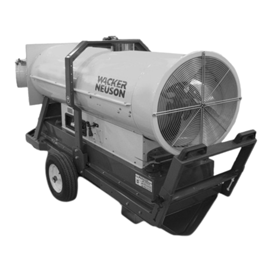
- Page 1 Operator’s Manual Indirect-Fired Air Heaters HI 400 HD D HI 400 HD G 0192824 1110...
- Page 2 This publication may be photocopied by the original purchaser of the machine. Any other type of reproduction is prohibited without express written permission from Wacker Neuson Corporation. Any type of reproduction or distribution not authorized by Wacker Neuson Corporation represents an infringement of valid copyrights. Violators will be prosecuted. Trademarks All trademarks referenced in this manual are the property of their respective owners.
- Page 3 Foreword Foreword This heater is designed and approved for use as a construction heater in accordance with Standard ANSI Z83.7–CSGA 2.14. CHECK WITH YOUR LOCAL FIRE SAFETY AUTHORITY IF YOU HAVE QUESTIONS ABOUT APPLICATIONS. Other standards govern the use of fuel gases and heat producing products in specific applications.
- Page 4 Use the separate Parts Book supplied with the machine to order replacement parts. If you are missing any of these documents, please contact Wacker Neuson Corporation to order a replacement or visit www.wackerneuson.com. When ordering parts or requesting service information, be prepared to provide the machine model number, item number, revision number, and serial number.
-
Page 5: Table Of Contents
HI 400HD D / HD G Table of Contents Foreword Safety Information Signal Words Used in this Manual ............7 Machine Description and Intended Use ..........8 Operating Safety .................. 9 Safety Guidelines for Gas-Fired Machines ......... 10 Safety Guidelines for Operating Combustion Burners ....... 11 Service Safety .................. - Page 6 Table of Contents HI 400HD D / HD G 4.21 Starting the Machine (D models) ............39 4.22 Starting the Machine (G models) ............40 4.23 Stopping ....................41 4.24 Burner Fault ..................41 4.25 Installing and Using the Remote Thermostat ........42 Accessories Available Accessories .................43 Burner Setup Removing the Access Panel ...............44 Removing and Installing the Burner ............45...
-
Page 7: Hi 400Hd D / Hd G
HI 400HD D / HD G Safety Information Safety Information Signal Words Used in this Manual This manual contains DANGER, WARNING, CAUTION, NOTICE, and NOTE signal words which must be followed to reduce the possibility of personal injury, damage to the equipment, or improper service. This is the safety alert symbol. -
Page 8: Machine Description And Intended Use
To protect yourself and others, make sure you thoroughly read and understand the safety information presented in this manual before operating the machine. Optional Wacker Neuson Corporation offers many optional accessories for the machine. accessories These accessories include the following: Remote thermostat Duct adapters (various sizes, available as kits, or individual ducts at 25 ft. -
Page 9: Operating Safety
Familiarize yourself with the location and proper use of all controls and safety devices. Contact Wacker Neuson Corporation for additional training if necessary. When operating this machine: Do not allow improperly trained people to operate the machine. People operating the machine must be familiar with the potential risks and hazards associated with it. -
Page 10: Safety Guidelines For Gas-Fired Machines
Safety Information HI 400HD D / HD G Keep the area immediately surrounding and underneath the machine clean, neat, and free of debris and combustible materials. Keep the area above the machine clear of debris that could fall on the machine. Keep unauthorized personnel, children, and animals away from the machine. -
Page 11: Safety Guidelines For Operating Combustion Burners
HI 400HD D / HD G Safety Information Safety Guidelines for Operating Combustion Burners When using the machine: Clean up any spilled fuel immediately. Replace the fuel tank cap after refueling the machine. Refill the fuel tank in a well-ventilated area. Make sure you have proper certification or licensing required by the locality, state, or province in which the machine is being installed to work with natural gas or Liquid Petroleum (LP). -
Page 12: Service Safety
Replacing When maintaining the machine: parts and When replacement parts are required for this machine, use only Wacker Neuson labels replacement parts or those parts equivalent to the original in all types of specifications, such as physical dimensions, type, strength, and material. - Page 13 Safety Information Accessories, When using the machine: safety devices Use only accessories/attachments that are recommended by Wacker Neuson Corporation. modifications When using the machine: Never operate the machine if any safety devices or guards are missing or inoperative. Do not defeat safety devices.
-
Page 14: Labels
Labels HI 400HD D / HD G Labels Label Locations ghi_gr007391 ghi_si000469gb.fm... -
Page 15: Label Meanings
HI 400HD D / HD G Labels Label Meanings WARNING! Hot surface! WARNING Entanglement hazard. Rotating machinery. Do not reach inside machine when engine is running. NOTICE Lifting point. WARNING! Electric shock hazard. Disconnect power before servicing. Read Operator’s Manual. CAUTION This machine uses diesel fuel. - Page 16 Labels HI 400HD D / HD G DANGER Using a heater indoors can kill you in minutes. Heater exhaust contains carbon monoxide. This is a poison you cannot see or smell. During indoor operation, vent exhaust gas outdoors. Refer to Operator's Manual. CAUTION Hot while in operation.
- Page 17 HI 400HD D / HD G Labels WARNING Licensed gas technician required. Natural gas / liquid propane burner setup and installation, fuel supply connection, test firing, and burner adjustment MUST be performed by a LICENSED professional gas technician and must conform to the requirements of all relevant local, state, provincial, and Federal authorities.
-
Page 18: Lifting And Transporting
Lifting and Transporting HI 400HD D / HD G Lifting and Transporting Lifting and Transporting Requirements Transport vehicle capable of carrying 1000 lbs (454 kg) Crane or lift capable of carrying 1000 lbs (454 kg) Background NOTICE: These machines are NOT designed to be towed with any vehicle. WARNING Crushing hazard. -
Page 19: Operation
1. Make sure all loose packaging materials have been removed from the machine. 2. Check the machine and its components for damage. If there is visible damage, do not operate the machine! Contact your Wacker Neuson dealer immediately for assistance. -
Page 20: Installing The Front Duct Adapter
Operation HI 400HD D / HD G Installing the Front Duct Adapter Overview The front duct adapter provided with your machine is shipped loose and must be installed before operating the machine. The thermostat probe must also be installed on the inside of the duct adapter during this procedure. Procedure Follow the procedure below to install the front duct adapter and thermostat probe. -
Page 21: Installing The Rear Duct Adapter (Optional)
HI 400HD D / HD G Operation Installing the Rear Duct Adapter (optional) Overview The optional rear duct adapter is shipped loose and must be installed before operating the machine. Procedure Follow the procedure below to install the rear duct adapter. 1. -
Page 22: Control / Component Locations
Operation HI 400HD D / HD G Control / Component Locations Machine components Description Description Exhaust flue Air inlet and fan guard Control panel Access panel Manual transport handle Fuel filter (D units) Fuel fill location (D units only) Gas train (G units only) Lift brackets Fork pockets ghi_tx001462gb.fm... -
Page 23: Adjusting The Handle Height
HI 400HD D / HD G Operation Adjusting the Handle Height Overview Your machine is equipped with a manual transport handle. The handle height can be adjusted to suit the operator’s preference. Procedure Follow the procedure below to adjust the handle height. 1. -
Page 24: Positioning The Machine
Operation HI 400HD D / HD G Positioning the Machine DANGER Exhaust gas from the burner contains carbon monoxide, a deadly poison. Exposure to carbon monoxide can kill you in minutes. Never run the machine indoors or in an enclosed area unless the machine is vented properly according to local and national codes. - Page 25 HI 400HD D / HD G Operation WARNING Fire hazard and electric shock hazards. The use of an inappropriate power sup- ply, or undersized extension cords, can lead to fire and electric shock. Fire and electric shock can cause severe injury. Before use, ensure that the machine is properly connected to an appropriate power source and grounded per the requirements provided below.
-
Page 26: Control Panel-Oil Burner (D Models)
Operation HI 400HD D / HD G Control Panel—Oil Burner (D Models) RESET Control panel components Description Description Burner fault lamp and reset Firing mode switch button (dual function) (High-fire or low-fire) Mode switch (on-off-on) Power indicator See topic Starting the Machine Remote thermostat receptacle Power cord Symbols and... -
Page 27: Recommended Fuels And Fuel Blending Guide (D Models)
Above 25 (-4) Winter-blend diesel Note: The burner on this machine was calibrated by test-firing for correct operation at Wacker Neuson Corporation located 180 m (600 ft.) above sea level using #2 diesel fuel combined with an anti-gelling additive. 4.10... -
Page 28: Control Panel-Gas Burner (G Models)
Operation HI 400HD D / HD G 4.11 Control Panel—Gas Burner (G Models) RESET wc_gr007770 Control panel components Description Description Burner fault lamp and reset Burner indicator button (dual function) Mode switch (on-off-on) Power indicator See topic Starting the Machine Remote thermostat receptacle Power cord Symbols and... -
Page 29: Gas Installation And Setup (G Models)
HI 400HD D / HD G Operation 4.12 Gas Installation and Setup (G models) WARNING Extreme explosion and fire hazards. Only a licensed, professional gas technician shall perform installation, fuel sup- ply connection, setup, adjustment, and testing of gas lines. Never use open flames to detect gas leaks. -
Page 30: Connecting The Gas Line (G Models)
Operation HI 400HD D / HD G 4.13 Connecting the Gas Line (G models) Overview The HI 400HD-G heater includes a 3/4” NPT inlet (a) on the gas safety valve / pressure regulator body. The gas supply line connects to the inlet. wc_gr007559 WARNING Extreme fire and explosion hazard! -
Page 31: Setting The Gas Selector Valve (G Models)
HI 400HD D / HD G Operation 4.14 Setting the Gas Selector Valve (G models) Overview Your machine is configured at the factory to operate on natural gas. The gas selector valve on the gas train allows you to convert the machine from natural gas to LP as job site conditions require. -
Page 32: Suggested Venting
When installing vents: Do not use B-vent exhaust pipes to vent an oil burning machine. Contact Wacker Neuson Product Support for recommended alternatives. Adhere to all local and national codes. Adhere to all fire prevention regulations. - Page 33 HI 400HD D / HD G Operation Note: The above venting diagram shows suggested venting layouts only. Consult all appropriate governing bodies or local contractor for venting and fresh air requirements. ghi_tx001462gb.fm...
-
Page 34: Installing The Heater Duct
Operation HI 400HD D / HD G 4.16 Installing the Heater Duct Overview Optional ducts can be connected to the air outlet. This allows warm air to be evenly distributed throughout the heating area. NOTICE: When using ducts, observe the static air pressure limits specified in Technical Data. -
Page 35: Installing The Remote Thermostat Or Receptacle Cap
HI 400HD D / HD G Operation 4.17 Installing the Remote Thermostat or Receptacle Cap Requirements Remote thermostat, or Thermostat receptacle cap Background The control panel includes a receptacle for an optional remote thermostat (b). The receptacle is protected by an attached cap (a) when not in use. NOTICE: To avoid damaging or contaminating the receptacle, make sure the cover is securely locked in place when a remote thermostat is not installed. -
Page 36: Connecting Power To The Machine (Preheating)
Operation HI 400HD D / HD G 4.18 Connecting Power to the Machine (Preheating) Requirements Power source (115VAC) Machine properly positioned Operation mode switch in the OFF (0) position WARNING Fire hazard and electric shock hazard. The use of under-sized extension cords can lead to fire and electric shock. -
Page 37: Starting The Machine In Extremely Cold Weather
HI 400HD D / HD G Operation 4.19 Starting the Machine in Extremely Cold Weather Background In temperatures below 32°F (0°C), it may be necessary to preheat the fuel inside the fuel filter canister. The fuel filter canister is equipped with a low-wattage heating element specially designed for this purpose. -
Page 38: Before Starting
Operation HI 400HD D / HD G 4.20 Before Starting Requirements Machine properly positioned Power connected to the machine Checks Before starting the machine, check the following items: Item Task Fuel sight gauge (if equipped) Check that the fuel tank is full (if applicable). Fuel tank cap Check that the fuel tank cap (if applicable) is secure. -
Page 39: Starting The Machine (D Models)
HI 400HD D / HD G Operation 4.21 Starting the Machine (D models) Requirements Machine properly positioned Power connected Pre-starting checks completed Procedure To start the machine, follow the procedure below. 1. Select an operation mode. a. Continuous heat mode (I) b. -
Page 40: Starting The Machine (G Models)
Operation HI 400HD D / HD G 4.22 Starting the Machine (G models) Requirements Machine properly positioned Power connected Pre-starting checks completed Procedure To start the machine, follow the procedure below. 1. Select an operation mode (b). a. Continuous heat mode (I) b. -
Page 41: Stopping
HI 400HD D / HD G Operation 4.23 Stopping Procedure Follow the procedure below to stop the machine. WARNING Electric shock hazard. Electric power is still active at the blower even when the machine is turned OFF. Remove all electric power to the machine before servicing the machine. 1. -
Page 42: Installing And Using The Remote Thermostat
Operation HI 400HD D / HD G 4.25 Installing and Using the Remote Thermostat Requirements Remote thermostat Pre-starting checks complete Procedure Follow the procedure below to install and use the remote thermostat. 1. Remove the thermostat receptacle plug (a) from the control panel receptacle. 2. -
Page 43: Accessories
Introduction Wacker Neuson Corporation offers many optional accessories for this machine. These accessories are described below. Contact your local Wacker Neuson dealer or visit www.wackerneuson.com for ordering information. Note: Depending on the specific machine model, your heater is equipped with one of three available outlet adapters. -
Page 44: Burner Setup
Burner Setup HI 400HD D / HD G Burner Setup Removing the Access Panel Requirements Machine shut down and cooled Machine properly positioned Over CAUTION Hot surface hazard. The machine surfaces may be hot. Allow the machine to cool for a minimum of ten minutes before touching it. Overview Your machine is equipped with a removable access panel. -
Page 45: Removing And Installing The Burner
HI 400HD D / HD G Burner Setup Removing and Installing the Burner Note: Although an oil burning machine (D model) is shown in the photos below, the procedure for removing the burner assembly on a gas burning machine (G model) is similar. - Page 46 Burner pressure Machine Nozzle size Fuel pressure in WC damper setting HI 400 HD D 2.00 (80W) gph Stage I: 160 Stage I: 11 — Stage II: 217 Stage II: 15 HI 400 HD G 3 x 2.8 mm —...
- Page 47 HI 400HD D / HD G Burner Setup HI Heater ghi_gr007395 Use the access hole in the exhaust stack. Several samples should be taken as the heater warms. The final sample should be taken just before the heater reaches 71°C (160°F). 8.
-
Page 48: Inspecting The Oil Burner Electrodes (D Models)
Refer to the table below to determine the condition of the electrode tips. wc_gr007619 Condition Task None; ok as-is None; ok as-is Replace The electrodes should be replaced if they are worn or damaged. Contact your Wacker Neuson dealer for replacement electrodes. ghi_tx001464gb.fm... -
Page 49: Checking/Changing The Burner Nozzle (D Models)
HI 400HD D / HD G Burner Setup Checking/Changing the Burner Nozzle (D models) Prerequisites Machine shut down and cool to the touch Machine properly positioned CAUTION Hot surface hazard. The machine surfaces may be hot. Allow the machine to cool for a minimum of ten minutes before touching it. When Replace the burner nozzle annually, or if it is damaged. -
Page 50: Adjusting The Burner Air Damper Setting
Burner Setup HI 400HD D / HD G Adjusting the Burner Air Damper Setting Requirements Machine shut down Power disconnected Procedure Perform the procedure below to check and adjust the burner air damper setting. 1. Shut down the machine and allow it to cool. 2. -
Page 51: Adjusting The Fuel Pressure (D Models)
HI 400HD D / HD G Burner Setup Adjusting the Fuel Pressure (D models) Requirements Machine shut down and cool to the touch Power disconnected Fuel pressure gauge Flat-bladed screwdriver Background The information below will show you how to check the fuel pressure on your machine. - Page 52 Burner Setup HI 400HD D / HD G Checking high 7. Set the mode switch to high fire mode (II). Wait approximately 30 seconds to pressure allow the burner to switch from Stage I to Stage II. 8. Verify the high pressure fuel pressure setting. For the correct setting, refer to the Technical Data charts in this manual.
-
Page 53: Maintenance
HI 400HD D / HD G Maintenance Maintenance Periodic Maintenance Schedule Interval* (hours of service) Daily 2 Weeks 6 Months Yearly Task (50) (1000) (1200) Inspect the heater. Inspect the hose assembly. Check fuel level and pressure. Clean the machine. Clean the fuel filter. -
Page 54: Changing The Fuel Heater Filter (D Models)
Maintenance HI 400HD D / HD G Changing the Fuel Heater Filter (D models) Prerequisites Machine shut down Burner cool CAUTION Hot surface hazard. The external surface of the fuel filter canister may be hot. Allow the machine to cool before servicing. WARNING Hot fluids. -
Page 55: Inspecting And Cleaning The Cadmium (Cad) Cell
HI 400HD D / HD G Maintenance Inspecting and Cleaning the Cadmium (CAD) Cell Prerequisites Machine shut down and cool to the touch Machine properly positioned CAUTION Hot surface hazard. The machine surfaces may be hot. Allow the machine to cool for a minimum of ten minutes before touching it. When Inspect and clean the CAD cell as needed, or while performing other scheduled maintenance procedures. -
Page 56: Cleaning The Fan Blades And Motor
Maintenance HI 400HD D / HD G Cleaning the Fan Blades and Motor Prerequisites Machine shut down and cool to the touch Power source disconnected WARNING Electric shock hazard. Electric power is still active at the blower even when the machine is turned OFF. -
Page 57: Cleaning The Interior Shell
HI 400HD D / HD G Maintenance Cleaning the Interior Shell Prerequisites Machine shut down and cool to the touch Power source disconnected CAUTION Hot surface hazard. The machine surfaces may be hot. Allow the machine to cool for a minimum of ten minutes before touching it. When Clean the interior shell prior to the first seasonal use, every 1200 hours or annually, or as needed. -
Page 58: Inspecting The Flame Head
Maintenance HI 400HD D / HD G Inspecting the Flame Head Prerequisites Machine shut down and cool to the touch Machine properly positioned CAUTION Hot surface hazard. The machine surfaces may be hot. Allow the machine to cool for a minimum of ten minutes before touching it. When Inspect the flame head prior to the first seasonal use, during regular maintenance, and as needed. -
Page 59: Inspecting The Electrical Connections
HI 400HD D / HD G Maintenance Inspecting the Electrical Connections After disconnecting the power cord, check all electrical connections for the following: Proper connections. Be sure that all connections are complete and tight. Corrosion. Clean or replace if necessary. Damaged wires/connectors. -
Page 60: List Of Abbreviations
Maintenance HI 400HD D / HD G List of Abbreviations ampere (unit of electrical current) above sea level British Thermal Unit °C Celsius (metric unit of temperature) °F Fahrenheit (unit of temperature) square foot/square feet (measurement of area) ft.lbs. foot pounds (unit of torque) gallons per hour (unit of liquid flow) Ground Fault Interrupt(er) (protection device) Hertz (unit of frequency) -
Page 61: Cad Cell
Note: The following symptoms and remedies are some of the more common issues that have arisen during the history of these machines. These do not represent all the possibilities. If you need advanced troubleshooting assistance, please contact Wacker Neuson Product Support. Symptom... -
Page 62: Technical Data
Technical Data HI 400HD D / HD G Technical Data Machine Model HI 400HD D HI 400HD G Units Heat input BTU/hr 412,682 354,610 Heat output BTU/hr 341,288 293,617 Air flow 3760 3821 Fuel consumption L (gal)/hr 11.2 (2.97) — Fuel consumption —... -
Page 63: Schematics
HI 400HD D / HD G Schematics 10 Schematics 10.1 HI 400HD D—Oil Burning 21 5 wc_gr007399 ghi_tx001467gb.fm... -
Page 64: Components-Oil Burning
Schematics HI 400HD D / HD G 10.2 Components—Oil Burning Description Description Fuse Burner motor Overheat thermostat Pre-heated filter plug Solenoid valve Summer/ winter switch CAD cell Overheat safety thermostat Capacitor Low fire / high fire power switch Fan motor Preheated nozzle Electric pilot lamp Control board heater... -
Page 65: Hi 400Hd G-Gas Burning
HI 400HD D / HD G Schematics 10.3 HI 400HD G—Gas Burning 19 20 21 YL/GN ghi_gr007400 wc_gr007400 ghi_tx001467gb.fm... -
Page 66: Components-Gas Burning
Schematics HI 400HD D / HD G 10.4 Components—Gas Burning Description Description Fuse Ionization probe Burner thermostat Burner motor Solenoid valve Summer/ winter switch Gas train Overheat safety thermostat Capacitor Fan thermostat Fan motor Flame lamp Electric pilot lamp Control board heater Transformer H.V. - Page 68 Fax: +49 - (0)89-3 54 02-390 Wacker Neuson Corporation · N92W15000 Anthony Ave. · Menomonee Falls, WI 53051 · Tel. : (262) 255-0500 · Fax: (262) 255-0550 ·Tel. : (800) 770-0957 Wacker Neuson Limited - Room 1701–03 & 1717–20, 17/F. Tower 1, Grand Century Place, 193 Prince Edward Road West, Mongkok, Kowloon, Hongkong.
Need help?
Do you have a question about the HI 400 HD D and is the answer not in the manual?
Questions and answers