
Related Manuals for Wacker Neuson HI750 Series


Summary of Contents for Wacker Neuson HI750 Series
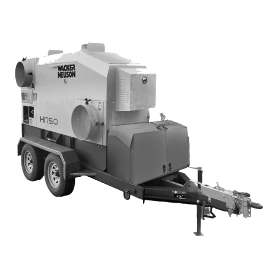
- Page 1 Operator’s Manual IDF Heater HI750 Type HI750 Document 5000192815 Date 1115 Revision Language 5 0 0 0 1 9 2 8 1 5...
- Page 2 Copyright notice © Copyright 2015 by Wacker Neuson Production Americas LLC All rights, including copying and distribution rights, are reserved. This publication may be photocopied by the original purchaser of the machine. Any other type of reproduction is prohibited without express written permission from Wacker Neuson Production Americas LLC.
-
Page 3: Foreword
HI750 Foreword Foreword This heater is designed and approved for use as a construction heater in accordance with Standard ANSI Z83.7–CSGA 2.14. CHECK WITH YOUR LOCAL FIRE SAFETY AUTHORITY IF YOU HAVE QUESTIONS ABOUT APPLICATIONS. Other standards govern the use of fuel gases and heat producing products in specific applications. - Page 4 Americas LLC will be referred to as Wacker Neuson. ■ Keep a copy of the Operator’s Manual with the machine at all times. ■ For spare parts information, please see your Wacker Neuson Dealer, or visit the Wacker Neuson website at http://www.wackerneuson.com/.
- Page 5 ■ Serious injury hazards to the operator and persons in the work area ■ Permanent damage to the machine which will not be covered under warranty Contact your Wacker Neuson dealer immediately if you have questions about approved or unapproved parts, attachments, or modifications.
- Page 6 Foreword HI750 ghi_tx001257gb_FM10.fm...
-
Page 7: Table Of Contents
Table of Contents HI750 Foreword Safety Information Signal Words Used in this Manual ............. 11 Machine Description and Intended Use ..........12 Operating Safety ................13 Safety Guidelines for Operating Combustion Burners ....... 15 Service Safety ..................16 Safety Guidelines for Operating Gensets ........... 18 Safety Guidelines for Towing the Machine ......... - Page 8 HI750 Table of Contents 4.15 Before Starting Checks ...............49 4.16 Connecting and Using the Remote Thermostat ........50 4.17 Starting the Generator (if equipped) ............51 4.18 Starting the Machine ................52 4.19 Stopping ....................53 4.20 Emergency Shutdown Procedure ............54 4.21 Monitoring the Operating Parameters ..........55 4.22 Overtemperature Shutdown ..............56 4.23...
- Page 9 Table of Contents HI750 Checking the Burner Air Damper Setting ........... 86 Adjusting the Head Setting ..............87 Checking the Supply Gas Pressure ........... 88 Checking and Adjusting the Burner Gas Pressure ......90 8.10 Changing the Burner Type (from Oil to NG or LP) ......92 8.11 Changing the Burner from Natural Gas Burning to LP Burning ..
- Page 10 HI750 Table of Contents 13.3 HI750 without VFD—Electrical Schematic ........138 13.4 HI750 without VFD—Electrical Schematic Components ....139 13.5 Kubota Genset ..................140 13.6 Kubota Genset Schematic Components ...........141 wc_bo5000192815_10_FM10TOC.fm...
-
Page 11: Safety Information
HI750 Safety Information Safety Information Signal Words Used in this Manual This manual contains DANGER, WARNING, CAUTION, NOTICE, and NOTE signal words which must be followed to reduce the possibility of personal injury, damage to the equipment, or improper service. This is the safety alert symbol. -
Page 12: Machine Description And Intended Use
Safety Information HI750 Machine Description and Intended Use Machine The HI750 Heaters are indirect-fired air heaters available in oil (diesel) burner and description natural gas or liquid propane (LP) burning models. The machine consists of the following components: ■ Combustion chamber and heat exchanger ■... -
Page 13: Operating Safety
HI750 Safety Information Wacker Neuson offers many optional accessories for the machine. These accessories include the following: ■ Remote thermostat ■ Duct adapters (various sizes, available as kits, or individual ducts). ■ Covers for inlet and outlets (need to be removed before operation) ■... - Page 14 Safety Information HI750 Guidelines for When operating the machine: operator ■ Remain aware of the machine’s moving parts. Keep hands, feet, and loose clothing away from the machine’s moving parts. ■ Wear protective clothing appropriate to the job site when operating the machine. ■...
-
Page 15: Safety Guidelines For Operating Combustion Burners
HI750 Safety Information Safety Guidelines for Operating Combustion Burners When using the machine: ■ Make sure you have proper certification or licensing required by the locality, state, or province in which the machine is being installed to connect natural gas or LP. -
Page 16: Service Safety
When using the machine: Accessories, safety devices, ■ Use only accessories/attachments that are approved by Wacker Neuson. modifications When using the machine: ■ Never operate the machine if any safety devices or guards are missing or inoperative. - Page 17 HI750 Safety Information Personal Wear the following Personal Protective Equipment (PPE) while servicing or Protective maintaining this machine: Equipment ■ Close-fitting work clothes that do not hinder movement (PPE) ■ Safety glasses with side shields ■ Hearing protection ■ Safety-toed footwear In addition, before servicing or maintaining the machine: ■...
-
Page 18: Safety Guidelines For Operating Gensets
Follow instructions carefully. Should questions arise during operation or service of this equipment, contact your Wacker Neuson dealer. ■ Keep a multi-class, type ABC or equivalent fire extinguisher at hand when using... - Page 19 HI750 Safety Information ■ Do not start the engine if fuel has spilled or a fuel odor is present. Running the genset ■ Keep the area around the exhaust pipe free of flammable materials. ■ Do not smoke while operating the genset. ■...
-
Page 20: Safety Guidelines For Towing The Machine
Safety Information HI750 Safety Guidelines for Towing the Machine WARNING Risk of severe injury or death. Improper trailer condition and towing technique can lead to an accident. ► Obey the trailer manufacturer’s instructions and the instructions below to reduce the risk of an accident. When towing the machine: ■... -
Page 21: Safety Guidelines For Lifting The Machine
If you believe your trailer has a defect which could cause a crash or could cause injury or death, you should immediately inform the National Highway Traffic Safety Administration (NHTSA) in addition to notifying Wacker Neuson. If NHTSA receives similar complaints, it may open an investigation; and if it finds that a safety defect exists in a group of trailers, it may order a recall and remedy campaign. -
Page 22: Labels
Labels HI750 Labels Label Locations BB C 1 = Skidded machines only 2 = Skidded machines with gas burners only ghi_si000380gb_FM10.fm... -
Page 23: Label Meanings
HI750 Labels Label Meanings NOTICE Lifting point 1166 kg (2567 LBS) (Skidded models only) 5200016796 WARNING Entanglement hazard. Rotating machinery. Do not reach inside machine when it is running. ghi_si000380gb_FM10.fm... - Page 24 Labels HI750 CAUTION This machine uses diesel fuel. DANGER Asphyxiation hazard. Heater exhaust contains carbon monoxide. This is a poison you cannot see or smell. Do not operate this machine indoors or in an enclosed area. Read the Operator’s Manual. (Trailered models only) WARNING! Electric shock hazard.
- Page 25 HI750 Labels Fuel drain Reset Fork lift pocket Tie-down point Handhold 176230 176230 Not a step 179212 A nameplate listing the model number, item number, revision number, and serial number is attached to each unit. Please record the information found on this plate so it will be available should the nameplate become lost or damaged.
- Page 26 Labels HI750 (Shore-powered machines only) Before starting heater: 1. Open the rear door. 2. Connect 240V/120V power to the heater. Start the heater: 1. Press and release the green start button. 2. Move the control switch: Position 1 = heat Position 2 = heat with remote thermostat Position 3 = fan only Shut down heater:...
- Page 27 HI750 Labels ghi_si000380gb_FM10.fm...
- Page 28 Labels HI750 WARNING Operation of This Equipment May Create Sparks That Can Start Fires Around Dry Vegetation. A Spark Arrestor May be Required. The Operator Should Contact Local Fire Agencies For Laws or Regulations Relating to Fire Prevention Requirements. Per CAL. PRC. CODE WARNING Operation of this equipment may create sparks that can start fires around dry vegetation.
-
Page 29: Lifting And Transporting
HI750 Lifting and Transporting Lifting and Transporting Lifting the Machine ■ Properly-rated lifting equipment (crane or hoist). See chapter Technical Data. Requirements ■ Machine stopped. See topic Stopping the Machine. ■ All doors and access covers closed and secured. WARNING Crushing hazard. - Page 30 Lifting and Transporting HI750 Procedure for Perform the procedure below to lift a trailered machine. trailered 1. Insert the forks of a lifting truck into the fork pockets (b). machines wc_gr007657 2. Lift the machine a small distance. WARNING Crushing hazard. An unstable machine may cause the lifting devices to fail. You may be crushed if the lifting devices fail.
-
Page 31: Preparing The Machine For Transport On A Truck Or Trailer
HI750 Lifting and Transporting Preparing the Machine for Transport on a Truck or Trailer ■ Machine stopped Requirements ■ Flatbed truck or trailer capable of supporting the machine’s weight ■ Chains, hooks, or straps capable of supporting the machine’s weight WARNING Crushing hazard. -
Page 32: Before Towing Checklist
Lifting and Transporting HI750 Before Towing Checklist Before towing the machine, check the licensing requirements for trailers in your area. Also check the following items: Hitch and coupler Check that the towing vehicle and hitch have a rating equal to or greater than the GVWR of the machine. -
Page 33: Testing The Breakaway System-Electric Brakes
HI750 Lifting and Transporting Testing the Breakaway System—Electric Brakes ■ Voltmeter Requirements ■ Battery charger or backup battery (charged) When Test the breakaway system: ■ Before towing ■ Monthly if the machine is not in service Procedure Perform the procedure below to test the breakaway system. NOTICE: Disconnect the trailer wiring plug from the tow vehicle before testing. - Page 34 Lifting and Transporting HI750 Continued from the previous page. 5. If the brakes did not function, check the voltage of the breakaway battery. To do so: a. Remove the cover of the battery box. b. Remove the wires connected to the breakaway battery (d). c.
-
Page 35: Testing The Breakaway System-Hydraulic Surge Brakes
HI750 Lifting and Transporting Testing the Breakaway System—Hydraulic Surge Brakes ■ Hydraulic reservoir filled Requirements ■ Machine parked on a flat surface When Test the breakaway system: ■ Before towing ■ After filling the hydraulic reservoir Procedure Perform the procedure below to test the breakaway system. 1. - Page 36 Lifting and Transporting HI750 Continued from the previous page. 7. Stop the tow vehicle. 8. Release the brake by simultaneously pulling on the breakaway cord and prying the locking spring with a screwdriver (c) or pry bar. wc_gr008510 Result The procedure to test the breakaway system is now complete. ghi_tx001259gb_FM10.fm...
-
Page 37: Operation
1. Make sure all loose packaging materials have been removed from the machine. 2. Check the machine and its components for damage. If there is visible damage, do not operate the machine! Contact your Wacker Neuson dealer immediately for assistance. -
Page 38: Refueling The Machine
Operation HI750 Refueling the Machine ■ Machine shut down Requirements ■ Machine level with the ground ■ Diesel fuel supply Procedure Perform the procedure below to refuel the machine. Note: On models with generators, it is not necessary to fill the generator’s fuel tank. -
Page 39: Features And Controls
HI750 Operation Features and Controls Ref. Description Ref. Description Exhaust rain cap Step Recirculation plate Trailer (diesel units only) Variable Frequency Drive (VFD) Natural gas/liquid propane burner with gas train (optional) (optional) Generator (optional) Diesel burner Air intake duct Blower assembly Trailer jackstand —... -
Page 40: Control Panel
Operation HI750 Control Panel Ref. Description Ref. Description Start button Voltage output meter Control switch Pressure gauge Hour meter — — General Sequence of Operation Follow the sequence of operation below. Refer to the specific topic for details. Task See Topic 1. -
Page 41: Positioning The Machine
► Do not operate the machine near flammable vapors, fuels, or combustibles. CO Alarms Because this machine produces carbon monoxide (CO), Wacker Neuson recommends that CO alarms be installed in all structures in close proximity to the machine. CO alarms provide an extra measure of protection against this poison that you cannot see or smell. -
Page 42: Electrical And Grounding Requirements
Operation HI750 Continued from the previous page. Procedure Perform the procedure below to position the machine. 1. Place the machine near the application area on solid, stable, and level ground. wc_gr008340 2. For machines with trailers, install chocks (a) under the wheels. Result The machine is now properly positioned. -
Page 43: Power Requirements For Third-Party Generators
HI750 Operation Power Requirements for Third-Party Generators NOTICE: Machine damage may occur if an undersized generator (genset) is used to power the machine. The starting kVA of the generator must be at least 33 kVA at a maximum voltage dip of 20%. 4.10 Connecting Power to the Machine Note: On machines equipped with generators, the power connections were made... -
Page 44: Connecting The Gas Line
Operation HI750 4.11 Connecting the Gas Line Overview The HI750G model heaters include a 1-inch NPT inlet on the gas safety valve/pressure regulator body. The gas supply line connects to the inlet. WARNING Extreme fire and explosion hazard! ► Only a licensed, professional gas technician shall perform installation, fuel supply connection, setup, adjustment, and testing of gas lines. -
Page 45: Suggested Venting
When installing vents: ■ Do not use B-vent exhaust pipes to vent an oil burning machine. Contact Wacker Neuson Product Support for recommended alternatives. ■ Adhere to all local and national codes. ■ Adhere to all fire prevention regulations. -
Page 46: Flex Ducting Options
Operation HI750 4.13 Flex Ducting Options Refer to the chart below for the maximum allowable return and supply duct lengths for your machine. NOTICE: Do not exceed the maximum total lengths specified in the chart. Exceeding these lengths, or blocking any of the duct openings, constricts the air flow through the machine and may cause a high-temperature shut-down fault. -
Page 47: Ducting Guidelines
HI750 Operation 4.14 Ducting Guidelines Use appropriate type (Heat range) and length of duct. Duct Types Use Black or Gray duct for supply air. Use Yellow duct for return air only. CAUTION Use of Yellow duct (rated for 200°F MAX) for supply ducting (required rating 280°F) can result in damage to the duct or unplanned shutdown if the ducting fails. - Page 48 Operation HI750 Avoid any sharp bends from the supply outlet. Use a stand to keep the duct level for a distance of 3–6 ft away from the machine. wc_gr013132 If additional ducting for a machine with more than one supply adapter is not available, change the adapter arrangement or use one adapter and leave the other adapters open.
-
Page 49: Before Starting Checks
HI750 Operation 4.15 Before Starting Checks ■ Machine properly positioned Requirements ■ Power connected to the machine Checks Before starting the machine, check the following items: Item Task Fuel Check that the fuel tank is full (if applicable). See topic Recommended Fuels. Check that the gas supply (if applicable) is connected and has the proper pressure. -
Page 50: Connecting And Using The Remote Thermostat
Operation HI750 4.16 Connecting and Using the Remote Thermostat ■ Remote thermostat Requirements ■ Machine shut down Procedure Perform the procedure below to install and use the optional remote thermostat. 1. Open the access panel (a) and locate the thermostat receptacle (b). 2. -
Page 51: Starting The Generator (If Equipped)
HI750 Operation 4.17 Starting the Generator (if equipped) Procedure Perform the procedure below to start the generator. 1. Open the generator access door (a). wc_gr007614 2. Set the circuit breaker (b) to the OFF position. 3. Turn the key switch (c) to the PREHEAT position (c ). -
Page 52: Starting The Machine
Operation HI750 4.18 Starting the Machine ■ Power connected Requirements ■ Generator started (if equipped) ■ Pre-starting checks complete Procedure Perform the procedure below to start the machine. 1. Check that the emergency stop switch (a) is in the disengaged position. wc_gr008344 2. -
Page 53: Stopping
HI750 Operation 4.19 Stopping Procedure Perform the procedure below to stop the machine. WARNING Electric shock hazard. Electric power is still active at the blower and at the control switch even when the machine is turned OFF. ► Disconnect all electric power from the machine before servicing it. 1. -
Page 54: Emergency Shutdown Procedure
Operation HI750 4.20 Emergency Shutdown Procedure Background This machine is equipped with an emergency stop push button. When pressed, this push button shuts down the machine and disconnects all power to the machine controls and the generator if equipped. NOTICE: Do not use the emergency stop push button for normal shutdown. Stopping the To stop the machine and disconnect power to the controls: machine... -
Page 55: Monitoring The Operating Parameters
HI750 Operation 4.21 Monitoring the Operating Parameters Background Monitor the machine while it is operating to ensure safe and efficient operation. Parameters Monitor the following parameters while the machine is operating. Parameter Notes Fuel level (“D” Add fuel as needed. models only) Voltage output Voltage output should be 240V... -
Page 56: Overtemperature Shutdown
Operation HI750 4.22 Overtemperature Shutdown Background The machine includes two high-temperature shutdown switches. The switches will shut down the machine if it experiences an overtemperature condition. During an overtemperature condition, the fault indicator (a) on the control panel will illuminate. The reset switches must be reset in order for the machine to return to operation. -
Page 57: Operating At High Elevations
Before operation 7.7 & 8.7 4. Replace the burner nozzle. Before operation High Wacker Neuson recommends using a 3.50-60° B @ 140 psi nozzle when operating Elevation at high elevations. Contact Wacker Neuson Product Support to order a Nozzle replacement nozzle. -
Page 58: Adjusting The Air Output Volume
Operation HI750 4.24 Adjusting the Air Output Volume Background The volume of heated air produced by your machine can be increased or decreased depending on job site requirements. Procedure Perform the procedure below to adjust the air output volume. 1. Loosen the locking handle (a) on the adjusting lever (b). –... -
Page 59: Using The Recirculation Damper
HI750 Operation 4.25 Using the Recirculation Damper NOTICE: Do not operate the machine with the inlet ports covered. Operating the machine with the inlet ports covered will cause the machine to shut down due to overheating. ► Opening the recirculation damper (a) introduces fresh air into the main air supply. -
Page 60: Operating States Of The Beckett Burner Controller
Operation HI750 4.26 Operating States of the Beckett Burner Controller WARNING Fire, explosion, asphyxiation, and burn hazards. ► Refer to the burner manufacturer’s documentation for safe operating procedures. reset button / lockout Yellow pump prime Green flame / recycle wc_gr007665 Operating State wc_gr007662... - Page 61 HI750 Operation State Action or Function The trial-for-ignition state immediately follows the valve-on-delay state. Trial-for- ignition During this state: ■ The fuel shut-off valve is opened (energized). ■ Pressurized fuel atomizes at the burner nozzle. ■ The atomized fuel is ignited by the electrodes. ■...
- Page 62 Operation HI750 Lockout The lockout state is described below. State Action or Function The burner will enter the lockout state for the following reasons: Lockout ■ Trial-for-ignition time has expired without flame being established. ■ Cad cell detects flame at the end of the valve-on delay state. ■...
- Page 63 HI750 Operation Recycle The recycle mode is described below. State Action or Function The burner will enter the recycle mode if the flame is lost while Recycle the burner is firing. During the recycle mode: ■ The burner control shuts down the burner. ■...
-
Page 64: Operating States Of The Riello Burner Controller
Operation HI750 4.27 Operating States of the Riello Burner Controller Start-up cycle Normal Lock-out, due to ignition failure Thermostat Motor Ignition transformer Valves Flame Lock-out max. 2s max. 2s wc_gr008351 Start-up cycle diagnostics During startup, the controller indicates the phase/state of the burner according to the following table. - Page 65 HI750 Operation Entering the burner controller diagnostic mode The burner controller includes a diagnostic mode/function through which causes of malfunctions may be determined. The controller sends out a sequence of pulses which are visible on the reset button/LED display. To enter the diagnostic mode: 1.
-
Page 66: Factory-Installed Options
Changing VFD The VFD is factory-set for the motor to reach full operating speed 5 seconds after settings startup. Contact your Wacker Neuson representative if there is a need to adjust the time interval. Trailer Overview Mobile HI750 IDF Heaters are mounted on trailers equipped with electric brakes or surge brakes, depending on the model selected. -
Page 67: Generator
The gas burner is fueled by Natural Gas (NG) or Liquid Propane (LP) depending on the user’s requirements. Electric power is also required to operate the machine and must be provided by an external source. Gas burner kit A gas burner conversion kit is available. Contact your Wacker Neuson dealer for more information. wc_tx001397gb_FM10.fm... -
Page 68: Accessories
Accessories HI750 Accessories Available Accessories Available The following Wacker Neuson accessories are available. Contact your Wacker accessories Neuson dealer for more information. Item Description/Purpose Remote thermostat Allows the user to remotely control the target temperature Inlet and outlet covers Vinyl covers that protect the interior of the machine... -
Page 69: Burner Setup-Diesel
HI750 Burner Setup—Diesel Burner Setup—Diesel Factory Settings Firing rate Fuel pressure Initial head Air band Head Nozzle size L/hr (gph) bar (psi) setting setting shutter CF 800 KJ 20.2 (5.34) 4.5 60° B 9.65 (140) Setting up the Burner Background The burner consists of several different components and subsystems. - Page 70 Burner Setup—Diesel HI750 Continued from the previous page. When Adjust the burner: ■ Before operating the machine at elevations 305 m (1,000 ft) above or below the location of the previous adjustments ■ Before starting at a new job site ■...
- Page 71 HI750 Burner Setup—Diesel Continued from the previous page. 9. Analyze the combustion. Follow the combustion analyzer manufacturer’s instructions and the general guidelines below. ■ Use the access hole in the exhaust stack. ■ Take several samples as the heater warms. ■...
-
Page 72: Setting And Checking The Electrodes
Burner Setup—Diesel HI750 Setting and Checking the Electrodes ■ Power supplies disconnected Requirements ■ Ruler or similar measuring device Procedure Perform the procedure below to check the electrodes. WARNING Fire and explosion hazard. Improperly maintained electrodes could cause ignition malfunction, blow-back of hot gases, heavy smoke, asphyxiation, explosion, and fire hazards. - Page 73 HI750 Burner Setup—Diesel Continued from the previous page. 7. Loosen the nut (e) and rotate the electrodes as necessary so that they match the dimensions below. Tighten the nut when finished. Note: The head (f) may be removed for improved access to the nozzle/electrodes. wc_gr008319 wc_gr009168 Ref.
-
Page 74: Replacing The Burner Nozzle
Burner Setup—Diesel HI750 Replacing the Burner Nozzle ■ Power supplies disconnected Requirements ■ New burner nozzle Procedure Perform the procedure below to replace the burner nozzle. 1. Disconnect the power from the machine. 2. Remove the screws (c) and open the burner cover. wc_gr008317 wc_gr008316 3. - Page 75 HI750 Burner Setup—Diesel Continued from the previous page. 7. Loosen the nut (e) and remove the clamp (f). Then, remove the head (g). wc_gr008327 wc_gr008328 8. Unscrew the nozzle (h) from the nozzle holder. 9. When finished, check the electrodes and reposition them if necessary. Installation Perform the procedure below to re-install the electrode assembly.
-
Page 76: Setting The "Z" Distance And Head Position
Burner Setup—Diesel HI750 Setting the “Z” Distance and Head Position ■ Burner removed from the machine Requirements ■ Straight edge ■ Ruler or similar measuring device Preliminary Perform the procedure below to set the “Z” distance. steps 1. Disconnect the copper fuel line from the nozzle assembly. 2. - Page 77 HI750 Burner Setup—Diesel Continued from the previous page. 3. Tighten the acorn nut (c). Result The “Z” distance has now been set. Continue by setting the head position. Set the head Perform the procedure below to set the head position. position 1.
-
Page 78: Adjusting The Air Settings
Burner Setup—Diesel HI750 Adjusting the Air Settings ■ Air band: 5 Factory settings ■ Air shutter: 5 These settings are initial settings only. Adjust the air settings as necessary to obtain the proper smoke spot and combustion analysis values. Background There are two parts to adjusting the air setting: 1) air band;... -
Page 79: Adjusting The Fuel Pressure-Oil Burner
HI750 Burner Setup—Diesel Adjusting the Fuel Pressure—Oil Burner ■ Pressure gauge Requirements ■ See Factory Settings for fuel pressure setting Procedure Perform the procedure below to check and adjust the fuel pressure. 1. Stop the machine. 2. Remove the bleeder valve (a) from the fuel pump. 3. -
Page 80: Burner Setup-Gas
Burner Setup—Gas HI750 Burner Setup—Gas Factory Settings HI750 Air damper setting 5.75 5.75 Combustion head setting Gas manifold pressure (in. w.c.) 4.05 Orifice (mm) Spring R6110-512 (blue) R6110-38 (pink) wc_tx001396gb_FM10.fm... -
Page 81: Setting Up The Burner
HI750 Burner Setup—Gas Setting up the Burner Background The burner consists of several different components and subsystems. Each of these components or subsystems must be operating correctly for the burner to function properly. Tools required The following tools are required to adjust the burner: ■... - Page 82 Burner Setup—Gas HI750 Continued from the previous page. 9. Conduct a smoke spot test. Follow the smoke spot tester manufacturer’s instructions and the general guidelines below. ■ Use the access hole in the exhaust outlet. ■ Take several samples as the heater warms. ■...
-
Page 83: Removing The Combustion Head
HI750 Burner Setup—Gas Removing the Combustion Head ■ Machine shut down Requirements ■ Burner cool Procedure Perform the procedure below to remove the combustion head assembly. 1. Open the access doors and locate the burner (a). wc_gr008490 wc_gr008489 2. Remove the burner assembly cover (b). 3. -
Page 84: Adjusting The Ionization Probe And The Electrode
Burner Setup—Gas HI750 Adjusting the Ionization Probe and the Electrode ■ Machine shut down Requirements ■ Burner cool Procedure Perform the procedure below to adjust both the ionizaton probe and the electrode. 1. Shut down the machine and allow it to cool. 2. -
Page 85: Changing The Burner Orifice
HI750 Burner Setup—Gas Changing the Burner Orifice ■ Machine shut down Requirements ■ Machine cool Procedure Perform the procedure below to change the burner orifice. 1. Shut down the machine and allow it to cool. 2. Remove the combustion head assembly (a). See topic Removing the Combustion Head Assembly. -
Page 86: Checking The Burner Air Damper Setting
Burner Setup—Gas HI750 Checking the Burner Air Damper Setting ■ Machine shut down Requirements ■ Burner cool Procedure Perform the procedure below to check the air damper setting. Note: This procedure must be performed at each new job site. The proper setting depends on environmental conditions at the job site. -
Page 87: Adjusting The Head Setting
HI750 Burner Setup—Gas Adjusting the Head Setting ■ Machine shut down Requirements ■ Machine cool Procedure Perform the procedure below to adjust the head setting. 1. Open the access doors and locate the burner (a). wc_gr008490 wc_gr008489 2. Remove the burner assembly cover (b). 3. -
Page 88: Checking The Supply Gas Pressure
Burner Setup—Gas HI750 Checking the Supply Gas Pressure ■ Machine shut down Requirements ■ Supply gas turned off ■ Manometer ■ Nipple Checking Perform the procedure below to check and adjust the supply gas pressure. pressure 1. Shut down the machine and allow it to cool. 2. - Page 89 HI750 Burner Setup—Gas Continued from the previous page. 7. Check the pressure reading on the manometer. See chapter Technical Data for the correct pressure. Adjust the supply gas pressure as needed. 8. After the supply gas pressure has been set, turn off the supply gas. 9.
-
Page 90: Checking And Adjusting The Burner Gas Pressure
Burner Setup—Gas HI750 Checking and Adjusting the Burner Gas Pressure ■ Machine shut down Requirements ■ Adequate supply gas pressure ■ Manometer Checking Perform the procedure below to check and adjust the burner gas pressure. pressure 1. Open the access doors and locate the burner (a). wc_gr008490 wc_gr008499 2. - Page 91 HI750 Burner Setup—Gas Continued from the previous page. Adjusting Perform the procedure below to adjust the burner gas pressure at the regulator (e). pressure wc_gr008501 ghi_gr004914 1. Check that the vent (g) is clean and open. 2. Remove the cap (f) from the regulator. wc_gr008502 3.
-
Page 92: Changing The Burner Type (From Oil To Ng Or Lp)
Burner Setup—Gas HI750 8.10 Changing the Burner Type (from Oil to NG or LP) ■ Burner Conversion Kit (contact Wacker Neuson Product Support) Requirements ■ Licensed gas installer ■ Combustion analyzer ■ Gas regulator (not supplied by Wacker Neuson) ■ You must have the proper licensing for your location. -
Page 93: Changing The Burner From Natural Gas Burning To Lp Burning
HI750 Burner Setup—Gas 8.11 Changing the Burner from Natural Gas Burning to LP Burning ■ Machine shut down Requirements ■ Machine cool Background The burner is set up at the factory to burn natural gas (NG). By changing the burner orifice and adding an air restricting washer, the burner can burn LP gas. -
Page 94: Changing The Gas Burner Regulator Spring
Burner Setup—Gas HI750 8.12 Changing the Gas Burner Regulator Spring ■ Machine shut down Requirements ■ Burner cool ■ Gas burner installed Procedure Perform the procedure below to change the gas pressure regulator spring. 1. Locate the gas pressure regulator (d). wc_gr008506 2. -
Page 95: Maintenance
HI750 Maintenance Maintenance Periodic Maintenance Schedule—Oil Burners The table below lists basic machine maintenance. Tasks designated with check marks may be performed by the operator. Tasks designated with square bullet points require special training and equipment. Interval* (hours of service) Daily 6 Months Yearly... -
Page 96: Periodic Maintenance Schedule-Gas Burners
Maintenance HI750 Periodic Maintenance Schedule—Gas Burners Interval* (hours of service) Daily 6 Months Yearly Task (1000) (1200) Check fuel level. Clean the machine. Inspect electrical components. Inspect the blower motor and belt. Replace the belt if necessary. ... -
Page 97: Cleaning The Machine
HI750 Maintenance Cleaning the Machine ■ Machine shut down Requirements ■ Machine cool General Clean the following areas to ensure proper operation. cleaning Item Method/task Burner Remove all dirt and debris. Ensure that the air intake area is unobstructed. Hoses, connectors, Wipe clean with cloth. -
Page 98: Replacing The Blower Belt
Maintenance HI750 Replacing the Blower Belt ■ Machine shut down Requirements ■ Burner cool Removal Perform the procedure below to remove the blower belt. procedure WARNING Electric shock and cutting injury hazard! ► Disconnect the main power supply to the machine before servicing the blower and blower belt. - Page 99 HI750 Maintenance Continued from the previous page. 2. Rotate the motor plate to apply tension to the belt. A properly adjusted belt will have approximately 3/8–1/2 in. (10–13 mm) of deflection at the center of the belt when pressed with moderate pressure. Or tension the belt by using 5–7 pounds (2.3 –3.2 kg) of pressure.
-
Page 100: Inspecting The Heat Exchanger
Maintenance HI750 Inspecting the Heat Exchanger Introduction The heat exchanger consists of the combustion chamber and an attached series of metal tubes. As intake air flows over the hot combustion chamber and tubes, it collects heat. The heated intake air is then blown out of the supply ducts. Reasons for A cracked or damaged heat exchanger is hazardous! Poisonous carbon monoxide inspection... - Page 101 HI750 Maintenance Continued from the previous page. Access Perform the procedure below to access the heat exchanger. procedure 1. Remove the side panels (a) from the machine and set aside. 2. Remove the heat shield panels (b). wc_gr013053 This procedure continues on the next page. ghi_tx001260gb_FM10.fm...
- Page 102 Maintenance HI750 Continued from the previous page. 3. Remove the four mounting bolts (k) and remove the burner (l). This enables inspection through the hole in the burner mounting flange (m). wc_gr008334 wc_gr008335 Inspection Perform the procedure below to inspect the heat exchanger. procedure 1.
- Page 103 HI750 Maintenance Continued from the previous page. 3. Use the light and mirror to examine the interior of the combustion chamber for cracks or separations. Also, inspect the burner mounting flange (m) for damage. wc_gr004505 wc_gr008338 4. Have an assistant shine the light (q) over the exterior shell of the combustion chamber while you peer through the hole in the mounting flange.
-
Page 104: Replacing The Burner Nozzle
Maintenance HI750 Replacing the Burner Nozzle ■ Power supplies disconnected Requirements ■ New burner nozzle Procedure Perform the procedure below to replace the burner nozzle. 1. Disconnect the power from the machine. 2. Remove the screws (c) and open the burner cover. wc_gr008317 wc_gr008316 3. - Page 105 HI750 Maintenance Continued from the previous page. 7. Loosen the nut (e) and remove the clamp (f). Then, remove the head (g). wc_gr008327 wc_gr008328 8. Unscrew the nozzle (h) from the nozzle holder. 9. When finished, check the electrodes and reposition them if necessary. Installation Perform the procedure below to re-install the electrode assembly.
-
Page 106: Replacing The Fuel Filter
Maintenance HI750 Replacing the Fuel Filter ■ Machine shut down Requirements ■ New fuel filter element and gasket kit Removal NOTICE: Do not remove the fuel filter assembly from the machine unless the filter housing cap needs to be replaced. The fuel lines are permanently attached to the fuel filter assembly. -
Page 107: Cleaning The Cad Cell
HI750 Maintenance Cleaning the CAD Cell ■ Power supplies disconnected Requirements ■ Clean rag Procedure Perform the procedure below to clean the CAD cell. 1. Disconnect the power from the machine. 2. Remove the screws (c) and open the burner cover (b). wc_gr008357 wc_gr008316 3. -
Page 108: Storage
Maintenance HI750 Storage Introduction Extended storage of equipment requires preventive maintenance. Performing these steps helps to preserve machine components and ensures the machine will be ready for future use. While not all of these steps necessarily apply to this machine, the basic procedures remain the same. When Prepare your machine for extended storage if it will not be operated for 30 days or more. -
Page 109: Preparing The Machine For Seasonal Operation
HI750 Maintenance 9.10 Preparing the Machine for Seasonal Operation Background After removing the machine from long-term storage, it must be prepared for operation. Perform the procedures below before each seasonal use. Before Perform the procedures below before you power up the machine. powering up machine Item... -
Page 110: Connecting And Maintaining The Battery
Maintenance HI750 9.11 Connecting and Maintaining the Battery WARNING Explosion hazard. Batteries can emit explosive hydrogen gas. ► Keep all sparks and flames away from the battery. ► Do not short-circuit battery posts. WARNING Battery fluid is poisonous and corrosive. ►... -
Page 111: Storing The Genset
HI750 Maintenance 9.12 Storing the Genset If the genset is to be idle for more than 120 days: 1. Change the engine oil. (Place a tag on the genset designating engine oil viscosity.) 2. Change the engine coolant. 3. Check all bolts and nuts, and tighten them as needed. 4. -
Page 112: Draining The Heat Exchanger And Resetting A Hard Lockout
Maintenance HI750 9.13 Draining the Heat Exchanger and Resetting a Hard Lockout WARNING Fire, explosion, asphyxiation, and burn hazards. Before starting or resetting the burner control from hard (restricted) lockout state, troubleshoot the heating system for the root cause(s) of the lockout. ►... -
Page 113: 10 Genset Maintenance
Kubota Genset Genset Maintenance 10 Genset Maintenance The engine maintenance schedule(s) in this chapter are reproduced from the engine owner’s manual. For additional information, see the engine owner’s manual. wc_tx003699gb_FM10.fm... - Page 114 Genset Maintenance Kubota Genset The viscosity of the engine oil is an important factor when determining the correct engine oil to use in your machine. Use an engine oil of appropriate viscosity based on the expected outside air temperature. See the table below. WARNING Most used liquids from this machine such as oil, gasoline, grease, etc., contain small amounts of materials that can cause cancer and other health problems if...
- Page 115 Kubota Genset Genset Maintenance wc_tx003699gb_FM10.fm...
-
Page 116: 11 Basic Troubleshooting
Worn burner nozzle Replace burner nozzle. and the unit locks out Faulty electrodes Replace electrodes. Faulty photoresistance Call Wacker Neuson Product Support. Faulty burner control Call Wacker Neuson Product Support. The burner starts, Incorrect fuel pressure Re-adjust fuel pressure. -
Page 117: Machines With Gas Burners
HI750 Basic Troubleshooting 11.2 Machines with Gas Burners Problem/Symptom Reason Remedy The burner goes to lockout Air has not been evacuated Check the gas train for leaks. after the pre-purge period from the gas lines. because the flame does not The gas valve is passing too Adjust the gas valve. -
Page 118: 12 Technical Data
Technical Data HI750 12 Technical Data 12.1 Machine Diesel 5000620856 5000620859 5000620857 5000620953 5000620930 Item Number: 5000620928 5000620924 (mobile, with 5000620929 (shore power) generator) HI750 Dimensions LxWxH 139x47x66 139x47x77 197x61x101 (cm) (353x119x166) (353x119x196) (500x155x255) Weight: with fuel lbs. — 2567 (1167) 4925 (2240) without fuel (kg) - Page 119 HI750 Technical Data Diesel 5000620856 5000620859 5000620857 5000620953 5000620930 Item Number: 5000620928 5000620924 (mobile, with 5000620929 (shore power) generator) Maximum return duct in. x ft. 2: 20 x 110 length (mm x m) (2: 508 x 33.5) Maximum supply in. x ft 3: 16 x 55 duct length (mm x m)
-
Page 120: Genset
Technical Data HI750 12.2 Genset Model Kubota GL7000 Frequency Rated output Rated voltage 120 / 240 Rated amperage 54.2 / 27.1 Phase & wire — 1 Ø / 4-wire Power factor Number of poles — Insulation Class Voltage regulation 5 (no load to full load) Type of coupling —... -
Page 121: Trailer
HI750 Technical Data 12.3 Trailer Item Number 5000620859 5000620930 5000620969 5000620970 Model HI750 DGM HI750 DGM HI750 DGM HI750 DGM GAWR 1588 1588 1588 1588 (Gross Axle Weight Rating) (lb) (3500) (3500) (3500) (3500) 381 x 152 381 x 152 381 x 152 381 x 152 (in.) - Page 122 Technical Data HI750 Notes ghi_td000360gb_FM10.fm...
-
Page 123: Tire Safety Information
Tire Safety Information Tire Safety Information Introduction to Tire Safety Information Federal Regulation 49 CFR 575 requires trailer manufacturers to include certain tire information in the owner’s manuals for the trailers they manufacture. This regulation requires that the information be in the English language. This chapter includes all the information required by Federal Regulation 49 CFR 575. - Page 124 Tire Safety Information wc_tx003108gb_FM10.fm...
- Page 125 Tire Safety Information Excessive loads and/or underinflation cause tire overloading and, as a result, abnormal tire flexing occurs. This situation can generate an excessive amount of heat within the tire. Excessive heat may lead to tire failure. It is the air pressure that enables a tire to support the load, so proper inflation is critical.
- Page 126 Tire Safety Information Bead The part of the tire that is made of steel wires, wrapped or reinforced by ply cords and that is shaped to fit the rim. Bead separation This is the breakdown of the bond between components in the bead. Bias ply tire A pneumatic tire in which the ply cords that extend to the beads are laid at alternate angles substantially less than 90 degrees to the centerline of the tread.
- Page 127 Tire Safety Information Intended outboard sidewall The sidewall that contains a white-wall, bears white lettering or bears manufacturer, brand, and/or model name molding that is higher or deeper than the same molding on the other sidewall of the tire or the outward facing sidewall of an asymmetrical tire that has a particular side that must always face outward when mounted on a vehicle.
- Page 128 Tire Safety Information A layer of rubber-coated parallel cords. Ply separation A parting of rubber compound between adjacent plies. Pneumatic tire A mechanical device made of rubber, chemicals, fabric and steel or other materials, that, when mounted on an automotive wheel, provides the traction and contains the gas or fluid that sustains the load. Production options weight The combined weight of those installed regular production options weighing over 2.3 kilograms (5 lbs.) in excess of those standard items which they replace, not previously considered in curb weight or accessory...
- Page 129 Tire Safety Information Tread rib A tread section running circumferentially around a tire. Tread separation Pulling away of the tread from the tire carcass. Treadwear indicators (TWI) The projections within the principal grooves designed to give a visual indication of the degrees of wear of the tread.
- Page 130 Tire Safety Information Tire safety tips. Use this information to make tire safety a regular part of your vehicle maintenance routine. Recognize that the time you spend is minimal compared with the inconvenience and safety consequences of a flat tire or other tire failure.
- Page 131 Tire Safety Information 1.5.4. S TEPS FOR AINTAINING ROPER RESSURE Step 1: Locate the recommended tire pressure on the vehicle's tire information placard, certification label, or in the owner's manual. Step 2: Record the tire pressure of all tires. Step 3: If the tire pressure is too high in any of the tires, slowly release air by gently pressing on the tire valve stem with the edge of your tire gauge until you get to the correct pressure.
- Page 132 Tire Safety Information 1.5.9.1. Information on Passenger Vehicle Tires Please refer to the diagram below. The "P" indicates the tire is for passenger vehicles. Next number This three-digit number gives the width in millimeters of the tire from sidewall edge to sidewall edge. In general, the larger the number, the wider the tire.
- Page 133 Tire Safety Information Tire Safety Information Letter Rating Speed Rating 99 mph 106 mph 112 mph 118 mph 124 mph 130 mph 149 mph 168* mph 186* mph * For tires with a maximum speed capability over 149 mph, tire manufacturers sometimes use the letters ZR. For those with a maximum speed capability over 186 mph, tire manufacturers always use the letters ZR.
- Page 134 Tire Safety Information 1.5.9.3. Additional Information on Light Truck Tires Please refer to the following diagram. Tires for light trucks have other markings besides those found on the sidewalls of passenger tires. The "LT" indicates the tire is for light trucks or trailers. An "ST"...
-
Page 135: 13 Schematics
HI750 Schematics 13 Schematics This page is intentionally left blank. ghi_tx001261gb_FM10.fm... -
Page 136: Hi750 With Vfd-Electrical Schematic
Schematics HI750 13.1 HI750 with VFD Electrical Schematic — F5 F5 B1 B1 180 ° ° F F H1 H1 K4 K4 PRE-HEATER WIRING PRE-HEATER WIRING F6 F6 33 33 15 A 15 A 44 44 41 41 21 21 PIN 3 PIN 3 PIN 1... -
Page 137: Hi750 With Vfd-Electrical Schematic Components
HI750 Schematics 13.2 HI750 with VFD Electrical Schematic Components — Ref. Description Ref. Description Beckett oil burner Cycle limit switch Burner controller High limit switch (in air outlet box) Cad cell Blower limit switch Emergency stop switch Blower motor Burner circuit breaker, 10A Control panel fan Fuse, 1A —... -
Page 138: Hi750 Without Vfd-Electrical Schematic
Schematics HI750 13.3 HI750 without VFD Electrical Schematic — 180°F F5 F5 K4 K4 33 33 21 21 44 44 41 41 F6 F6 185°F 212°F 1A 1A H1 H1 F3 F3 PRE-HEATER WIRING PRE-HEATER WIRING S2 S2 32 32 A1 A1 14 14 11 11... -
Page 139: Hi750 Without Vfd-Electrical Schematic Components
HI750 Schematics 13.4 HI750 without VFD Electrical Schematic Components — Ref. Description Ref. Description Emergency stop switch High limit switch (in air outlet box) Burner circuit breaker, 10A Blower limit switch Fuse, 1A Blower motor Fuse, 2A Control panel fan Fuse, 2A Motor controller Magnetic circuit breaker, 15A... -
Page 140: Kubota Genset
Schematics HI750 13.5 Kubota Genset wc_gr008375... -
Page 141: Kubota Genset Schematic Components
HI750 Schematics 13.6 Kubota Genset Schematic Components Ref. Description Ref. Description Sub winding Glow plug Excitation winding Starter Main winding Battery voltmeter Engine block Full power switch Enclosure block Circuit breaker Regulator Emergency unit Slow blow fuse Control box Fuse box Hour meter Relay B Starter switch... - Page 144 Wacker Neuson Production Americas LLC, N92W15000 Anthony Ave., Menomonee Falls, WI. 53051 Tel.: (262) 255-0500 Fax: (262) 255-0550 Tel.: (800) 770-0957 Wacker Neuson Limited - Room 1701–03 & 1717–20, 17/F. Tower 1, Grand Century Place, 193 Prince Edward Road West, Mongkok, Kowloon, Hongkong. Tel: (852) 3605 5360, Fax: (852) 2758 0032...
Need help?
Do you have a question about the HI750 Series and is the answer not in the manual?
Questions and answers