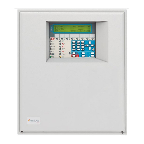
FireClass FC503 Installation Manual
Addressable fire control panels
Hide thumbs
Also See for FC503:
- User manual (88 pages) ,
- Programming manual (26 pages) ,
- Quick start setup manual (16 pages)

Related Manuals for FireClass FC503


Summary of Contents for FireClass FC503
- Page 1 FC503 & FC506 Addressable Fire Control Panels Installation Manual Doc. Version 2.0 23 October 2019...
- Page 2 DANGER compliance with the local laws and bylaws in force. Death or severe injury when The FC503 and FC506 fire control panels comply with the disregarded. essential requirements of standards EN54-2, EN54-4 and Warning. EN54-21. Potentially...
-
Page 3: Table Of Contents
Using the system ............31 Introduction ..............5 Operating the system from the panel ......31 FC503 & FC506 fire control panel ......... 5 Assistant text composition ..........32 Accessory items ............. 5 MAIN screen - accessing the system ......34 Description .............. - Page 4 FC410QIO Quad input output module ......65 FC440SB Addressable Base Sounder ......65 FC440AVB Addressable Sounder Base VAD Sounder 65 FC503/6 Firmware upgrade quick guide ....... 66 Firmware upgrade procedure using FireClass FC500 (FC501_FC503_FC506) Console software ....66 Firmware upgrade procedure using the USB pen drive ..................
-
Page 5: Introduction
Controls’ highest standards of quality and performance. This is a user-friendly software application that has Microsoft Windows 7 and higher. The console offers easy Find further details on the FC503 and FC506 fire control ways to program the control panel and also provides event panels below: log functions. - Page 6 Delay to Alarm Day and night mode If a zone generates an alarm during Day Mode, the control The control panel can operate in Day or Night Mode. See the relevant section in the “PC Programming” chapter. panel starts the Delay to Alarm Time. The Delay to Alarm status signals are: If you silence the system in Day Mode, the Silence status •Control panel buzzer;...
- Page 7 Table 2: Description of faults Message Problem Mains fault The control panel is not powered from the mains The control panel’s batteries charger not working properly Battery Low battery The control panel batteries are empty Earth Leakage to earth 24A Output Shorted 24A Output 24R Output Shorted 24R Output...
-
Page 8: Interface
Note: You can only mute the Silenceable outputs manually Table 3: Audible Signaling at access level 2 or 3. Status Sound Pause Frequency Disabled SYSTEM This control panel can disable the devices on the loop, FAULT SC2 output, OC1 and OC2 outputs, the software zones, 2.5 s 2.8 s 1300 Hz... -
Page 9: Power Supply
Power supply Use the SILENCE key to restore the Silenceable outputs The power supply system of the FC503 & FC506 control to standby status. If the control panel operates in Night panels complies with EN54-4. All models are powered by Mode, Silence remains until the programmed Night Mode the mains. -
Page 10: The Status Led
Delay to Alarm, Warning or Fault signal that Reset For the Evacuate, Lamp or Buzzer Test, Investigate, operations did not clear. Silence Buzzer keys, see Table 4. When Reset is running, the command keys are inoperative. Any FC500 repeaters connected to the panel can carry out resetting the fire panel. - Page 11 Table 5: Description of the status LEDs. Description FIRE (Red) ON indicates the alarm status. In the event of an alarm, the control panel activates the unbypassed alarm outputs. GENERAL ON indicates the presence of a fault. The following LEDs or the screen display FAULT indicates the type of fault.
-
Page 12: Parts Identification
Screws (2) to close the cover on panel Description of parts Knockout for connection FC503, FC506 panel with FC500BX battery cabinet This section describes the components of the FC503 and (accessory item) (1) FC506 control panels. Display Unless otherwise stated, the numbers in boldface in this Knockouts for cables ducted externally manual refer to the tables and diagrams in this section. - Page 13 Figure 2: FC503 and FC506 Parts: Internal view Hooks to secure the cover on the panel (2) Panel anchor screw locations (Top) (2) Terminals (2) for the earth connection wires Earthing Cables (2) Panel anchor screw locations (Bottom) (2) Screws to secure main board (4)
- Page 14 Figure 3: Main module parts Terminals for phone line connection Loop 1 (sub loop 1) Loop 2 (sub loop 2) USB port Loop 3 (sub loop 3) RS485 serial port Loop 4 (sub loop 4) Fire and Fault relay outputs Loop 5 (sub loop 5) SC outputs Loop 6 (sub loop 6)
- Page 15 Figure 4: BAQ140T24 Switching-power-supply Notes: Before connecting the fire control panel to the PC for the PC programming phase, remove the jumper of the main board. See Figure 3, item 10. When the programming phase finishes, replace the jumper to ensure the Earth fault or Leakage to Earth is detected.
-
Page 16: Installation
13. Program the control panel in accordance with the the paragraph Installing the FC500IP board. instructions in the FC503 & FC506 Addressable Fire Control Panels User Manual and the FC503 & FC506 Addressable Fire Control Panels PC Programming CAUTION Manual. - Page 17 Figure 5: Chassis mounting details Mounting studs Mounting slots Figure 6: Cabinet dimension details Note: All dimensions are in mm. Mounting holes...
- Page 18 Figure 7: FC500 repeater installation Holes for cabinet mounting (4) Screws to secure main module (4) Connector for the repeater RS485 interface Earthing cable Terminal for the earth connection wires LED label slot User interface repeater board Knockouts for cables ducted externally (One on each side) Hooks to secure the cover on the panel Screws to secure cover (2)
-
Page 19: Installing Fc500 Repeater
The six sub loops of the panel can manage up to 500, This section describes the control panel terminals. maximum of 250 in a single main loop, addressable FC503 devices. The total length of the cables connected to the three Main loop 1 loops must not exceed 2000 m. -
Page 20: Fault
only with the FC503_FC506 software. During standby status, negative pull-down to 0 V on [+] During standby status, terminal [C] closes to terminal terminal; positive pull-up to 27.6 V on the [–] terminal. When a programmed event occurs, positive pull-up to [NC]. -
Page 21: Rs485
Note: This power supply disconnects for 2 seconds when Connecting addressable devices resetting the control panel, so it suits devices that restore The control panel FC503 has one main loop or three sub when the power supply disconnects. loops for addressable analogue devices. The control panel... -
Page 22: Connecting Repeater Fc500
For an example of how to connect two FC500 repeaters, As there is only one control panel in the system, it must Figure 10.The RS485 port of the FC503, terminals supply the repeaters with power, unless a power supply [GND], [A], [B] and [24V], accepts up to eight FC500 station is in the system. - Page 23 Figure 9: Wiring diagram of a 4-wire connection A) Isolators B) Compatible analogue devices (Fire detector, Input modules, Output modules, Manual callpoints) Figure 10: Wiring diagram of eight (max) FC500 repeaters connected to the RS485...
-
Page 24: Connecting Output Devices
Figure 11: Wiring diagram of the connection of a single device (a) Connecting to several devices (b) Connecting to bell outputs (device activated by positive (27.6 V) on terminal [A+]) Force the bell outputs to standby using the SILENCE Connecting output devices button. -
Page 25: Connecting The Power Supply
In order to comply with the safety Board. Wires are supplied. regulations in force, the mains must be FC503 and FC506 use 17 Ah or 38 Ah @ 12 V Power equipped with a bipolar isolating device for Sonic batteries or similar. -
Page 26: Thermal Probe
Figure 13: Wiring diagram for the power supply panel main board. Black wire Red wire Battery 12V CAUTION Jumper Before removing the probe, disconnect the Automatic Isolating Switch battery from the main board. Removing the thermal probe causes the switching power supply voltage to rise to 27.6 V or greater. - Page 27 Figure 14: Switching power supply output voltage graph TEMPERATURE (°C) Finding the output voltage using the graph Indicate the probe temperature on the TEMPERATURE (°C) axis. Draw a line from the temperature value point up to the curve a) and draw a line from the intersection point across to the VOLTAGE (V) axis.
-
Page 28: Installing The Fc500Ip Board
(item 11). to the LAN using an Ethernet cable. Note: Use a category 5 or greater Ethernet cable, Figure 15: FC503 connection with the FC500IP STP, or FTP. Do not remove the wiring already present on the screw PC Link cable (item 11). -
Page 29: Installing The 38Ah Battery Metal Box
Users must carry out the following operations regularly: Installing the 38Ah battery metal box Work carefully through the following steps for the FC503 Use a damp cloth to remove dust from the control and FC506 fire panel only. See Figure panel cabinet. -
Page 30: Verifying The Functionality Of The Circuit
Verifying the functionality of the circuit The purpose of verifying the circuit's functionality is to ensure the circuit can detect faults. Connect one of the loops’ SH terminals to the ground. Verify that the fire panel correctly reports the fault Remove any connection points previously made. -
Page 31: Programming From The Panel
Use the alphanumeric keypad, the cursor keys, the ESC panel. key, and the ENTER key to manage the system from the user interface (main panel). For PC Programming help, refer to the FC503 & FC506 Addressable Fire Control Panels PC Programming Alphanumeric keypad Manual. -
Page 32: Assistant Text Composition
In this phase the keypad and keys have the following Assistant text composition functions: To simplify the entry of text strings, an assisted procedure has been included, based on a pre-compiled list of 128 Alphanumeric keypad vocabulary words with a maximum of 18 characters. When No function is related to the alphanumeric keypad. - Page 33 ESC and ENTER keys Numeric entry Use numeric entry to enter numeric data up to 20 digits. Table 13: ESC and ENTER key function in multiple selection In this phase the keypad and keys have the following Function functions: Use to cancel the operation and return to the previous screen ENTER Use to accept the programmed...
-
Page 34: Main Screen - Accessing The System
30 seconds, the user interface leaves the MAIN screen and reaches the front screen. For more features refer to the description of the MAIN screen in the FC503 & FC506 Addressable Fire Control Panels User Manual. Insert password Select the 1 key, Program, from the MAIN screen to insert the installer password required to operate at L3. -
Page 35: Program Screen
PROGRAM screen 0 Key - insert modify password From the MAIN screen, press the 1 key to select the PROGRAM screen. Enter the password. See Figure On the PROGRAM screen, press the 0 key to modify the Level 3 Installer password. The default password is 00000 and every digit will be masked by an asterisk. -
Page 36: Key- Auto-Enrolling (Auto-Learning)
Figure 22: Modify password screen Figure 23: Auto scan results screen Control panel name Access level Control panel status If blinking, control panel working properly Field to insert password Auto Use the Auto option from the PROGRAM menu to enroll the loop devices and the RS485 network devices automatically for repeater FC500. - Page 37 Scheme 2: Each zone contains two device addresses. Zone Alarm For Main Loop 1 of FC503, assign devices from zone 1 to Panel Alarm zone 125. For Main Loop 1 of FC506, assign devices from...
-
Page 38: Auto-Addressing Procedure
Function The auto addressing procedure is part of the loop devices Use to cancel the operation and enroll process in the FC503 and FC506 panels. return to the MAIN screen ENTER Use to activate the device To initialize the loop devices enroll process follow these... - Page 39 The control panel is ready to work at this time with the default basic programming. Optionally, you can set the system addresses differently. To set the system addresses differently, complete the following steps: 1. Press the ENTER key, so the fire panel initiates the MAPPING DEVICES phase.
-
Page 40: Key - Device
The Device option in the PROGRAMMING menu activates the screen used to select and program the devices on the loops. See Figure 24. Choose the loop For more information, refer to View devices in the FC503 & FC506 Addressable Fire Control Panels User Manual. - Page 41 In this phase the keypad and keys have the following Cursor keys functions: Table 35: Cursor key functions in choose the device Function Alphanumeric keypad No function Down No function Table 32: Alphanumeric keypad function in choose the Right Use to select the next available loop device Function...
-
Page 42: Key - Sw Zone
Note: The Remote LED can also be programmed on the FireClass FC500 (FC501_FC503_FC506) Console in the programming screen for the detectors. Separated programming of the sounder and beacon... - Page 43 Cursor keys Cursor keys Table 38: Cursor key functions in SW zone Table 40: Cursor key functions in SW zone in WALK Function TEST No function Function No function Down No function Down No function Right Use to select the next available SW zone Right Use to select the next ON-OFF-...
-
Page 44: Key - Output
If a new alarm from the same detector or the activation of Figure 27: Programming option delay detector alarm another sensor in the same zone occurs within 30 minutes, verification the alarm of fire panel is triggered. In this phase the keypad and keys have the following functions: Alphanumeric keypad No function is related to the alphanumeric keypad. - Page 45 Alphanumeric keypad This feature is also available for Panel FIRE relay and FC410RIM, FC410SIO, FC410MIO, FC410QMO, Use the alphanumeric keypad to enter the number of SC FC410QRM, FC410QIO loop modules. output. OUTPUT NAME TRIGGER ZONE 1 Cursor keys ...
-
Page 46: Key- Network
The entry 0000 means No Zone. Figure 24, 0. Numeric entry modes range from 0 to 128 for FC503 and 0 2. Use the left and right arrow keys or the ^ symbol under the name of the selected module to select the to 256 for FC506. -
Page 47: Key - Map Device
working automatically modify devices labels and assigned zone. ko! The net. device is sensed as not connected FAU The net. device is faulty Note: All the devices, including the unique type devices will DIS The net. device is disabled be added to the activated list. - Page 48 USB key flash memory while the panel is running. Download the two languages from the CD supplied with the panel or from the FireClass website. Load the audio file containing the voice messages from the USB pen drive to the...
-
Page 49: Key - System
USB to panel fails, a fault page is displayed and the configuration files. default Italian language is restored. -PANEL TYPE (FC503 or FC506) Figure 35: Select the language of the system -BATTERY TYPE (17Ah or 38Ah) Day / Night / Auto The display for programming Day, Night, or Auto mode will be shown. -
Page 50: Key- Restore Default
FC500IP module, the procedure to restore factory Default (9 key) will have no effect. To restore the FC500IP module to factory default refer to the procedure for the FireClass In this phase the keypad and keys have the following FC500 (FC501_FC503_FC506) Console software. -
Page 51: Modify
Modify all the options described in the User Manual. Accessing the MODIFY menu Refer to the FC503 & FC506 Addressable Fire Control Panels User Manual for User Access details To access the MODIFY menu from the MAIN screen, and further information. -
Page 52: Disable
The INSTALLER 1 and INSTALLER 2 users can access ENTER Confirm the selection all the options described in the user manual. Refer to the FC503 & FC506 Addressable Fire Control Panels User Disable the password Manual for more information. In this phase, the display shows the current status of the selected User or Installer password. - Page 53 Figure 39: Display enabled or disabled password Control panel name Access level Control panel status If blinking, control panel working properly Request to enable or disable Current status Password type...
-
Page 54: Quick Start-Up Procedure
This information includes: The FC503 control panel will take over all selected language devices with an address between 1 and 250. panel identification number ... - Page 55 Figure 24, 3 Device mapping The third and last phase is activated on demand at the end of the auto-addressing phase. If you stop the AUTO option at the end of the second In this phase, the following options are possible: phase, the following results occur: ...
-
Page 56: System Default
Zone 3: all the devices located on Loop 3 (sub loop 3) generation device from the FC400 series. For FC503: The address is in the range of 1 to 250. For FC506: The address for the 1st loop is in the 2. - Page 57 System default parameters mode Day CO Medium Temperature Detector Default values sensitivity Label See note (**) Night temp. Enablement Enabled operating mode LED blink Night CO mode Normal Assigned zone (see: "Zone Night CO Medium assignment) sensitivity Base type Normal Use zone setting Modules Default values...
- Page 58 Enablement Enabled Channel label Tttt y (****) Enablement Enabled Trigger zone #1 None LED blink Trigger zone #2 None External power Trigger zone #3 None Detector type 4/20 mA Source Trigger zone #4 None Threshold set Set #1 Trigger point #1 None Trigger point #2 None...
- Page 59 (**) Automatically assigned Module label. The label is composed by a brief description of the device followed by its address. Automatically assigned Module channel label The label is composed by a first part containing the module acronym and address followed by the brief description of the channel using the acronym printed on the module PCB.
-
Page 60: Accessories
Accessories The following is a list of accessories for FC503 and beacon base. FC506 control panels with a description of the main features. For further information about these accessories, Software within the controller is used to interpret the refer to the instructions supplied with the accessories or... -
Page 61: Fc410Mim Mini Input Module
The type of alarm generated by the the IN+ and IN- terminals, i.e., no field wiring. The remote callpoint is configured in the FireClass FC500 LED (if required, not supplied) must be located within the (FC501_FC503_FC506) Console. The FC421CP same electrical enclosure. -
Page 62: Fc490St Loop Service Tool
Two spur circuits (Class B) monitoring multiple to raise alarm or other appropriate response according to normally open contacts, with short circuit giving an the type of detector configured in the FireClass FC500 alarm (FC501_FC503_FC506) Console. FC410DIM Detector input module... -
Page 63: Dpk4 And Dpk4I
Sounder/ Sounder-Beacons are designed to be driven narrow beam of IR light in order to monitor for smoke and from a FC503 or FC506 control panel through the is controlled using a compact low level controller. It addressable loop. The FC410LPBS series of sounders... -
Page 64: Fc430Lpsb And Fc430Lpasb Loop Powered Addressable Sounder Beacon Base
The FC430LPBS series of loop powered addressable sounder and sounder- beacons are designed to be addressable sounder beacon base driven from an FC503 or FC506 control panel from the The FC430LP series of loop powered addressable addressable loop. Tone, volume, and flash rates are set... -
Page 65: Fc410Ddm Universal Fire And Gas Detector Module
FireClass FC500 (FC501_FC503_FC506) detectors, or two 4-20 mA signaling sensors, to the Console. FireClass fire alarm controller. The FC410DDM monitors Selectable flash rates are: the status of the detectors and the wiring to the detectors a) 1 Hz (flash every second) and signals detector and wiring status back to the b) 0.5 Hz (flash every 2 seconds) -
Page 66: Fc503/6 Firmware Upgrade Quick Guide
2. If you are using a USB cable, insert the USB cable into the PC host port and install the USB driver when asked. 3. Find the correct drivers in the FireClass FC500 (FC501_FC503_FC506) Console Software installation directory: C:\Program Files\FireClass\FireClass_FC500_Console \Drv. -
Page 67: Firmware Upgrade Procedure Using The Usb Pen Drive
Firmware upgrade procedure using the USB pen drive 1. Access the updated firmware packet from the FireClass website; the correct file name has the ‘FWxxxxxxBIN’ format. 2. Get a FAT or FAT32 USB pen drive. 3. Create a folder named ‘F_FW’ at the root of the USB pen drive. -
Page 68: Specifications
FIRECLASS training. terminal, as well as the maximum current in amps that Technical features can circulate. Table 62: FC503 and FC506 technical features Control panel FC503 FC506 230 V~ 230 V~... - Page 69 Table 64: Terminals description TERM. Description v(V) i(A) Main boards — — +L1- LEFT (+)Loop 1-Positive signal, left side. (-)Loop 1-Negative signal (return), left side +L1- RIGHT (+)Loop 1-Positive signal, right side. — — (-)Loop 1-Negative signal (return), right side +L2- LEFT (+)Loop 2-Positive signal, left side.
- Page 70 Table 65: Current distribution of FC506 control panel FC506 control panel Switching power supply BAQ140T24 (Imax = 5.5 A) = (12*0.8)/24 = 400 mA Battery_Charge_80%_24H 12 Ah Battery = 5500 - 400 = 5100 mA For_panel Panel load distribution = 250 mA Main_Board_Electronics (*) = 800 mA @40V (1300 mA @27V) Total_Loops_1_2_3...
- Page 71 (****): If the FC500IP module is not be used then the relative amount of current (100 mA) can be drawn from the SC1, SC2, 24A, 24R, 24V-RS485 terminals. Table 67: Max withdrawable current for FC503 and FC506 control panels Terminals Max Current 0.5 A...
-
Page 72: Cpr Information
0051 Tyco Fire & Security GmbH, Victor von Bruns-Strasse 21, 8212 Neuhausen am Rheinfall, Schaffhausen, Switzerland DoP-2018-4260 (FC503/ FC506 with optional FC500IP module) EN 54-2:1997+A1:2006 EN54-4: 1997+A1:2002+A2:2006 EN 54-21: 2006 Control and indicating equipment with integrated power supply equipment for fire detection and fire alarm systems for buildings with alarm transmission and fault warning routing equipment.
Need help?
Do you have a question about the FC503 and is the answer not in the manual?
Questions and answers