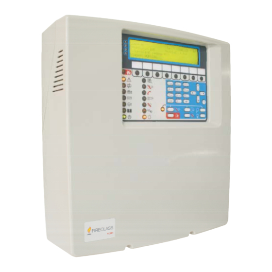
FireClass FC501 Installation Manual
Addressable fire control panels
Hide thumbs
Also See for FC501:
- Installation manual (72 pages) ,
- Quick start setup manual (52 pages) ,
- Pc programming manual (32 pages)
Table of Contents
Advertisement
Quick Links
FC501 Addressable Fire Control
Panels
You have the option to program the fire control
panel manually, or through a USB key, or by using
the Software FireClass FC500 (FC501_FC503_FC506)
Console release 01.00.01 or higher. Use control
panel FW version 1.14 or higher.
Johnson Controls assumes no responsibility for
damage to products resulting from improper
application or misuse.
Installation of this control panel must take place
strictly in accordance with the instructions in this
manual and in compliance with the local laws and
bylaws in force.
The FC501-L, FC501-H and FC501-HK fire control
panels comply with the essential requirements of
standards EN54-2, EN54-4 and EN54-21.
Note: The FC501-L, FC501-H and FC501-HK fire
control panels support several addressable
devices such as detectors, modules, and
manual call points. This manual includes the
instructions for the programming of the fire
control panels. For further information on
these devices and their accessories, visit
www.fireclass.com
Area, under Installation Manuals.
The manufacturer reserves the right to change the
technical specifications of these products without
prior notice.
FC501 Addressable Fire Control Panels
http://
and log into the Reserved
Installation Manual
Box contents
The control panel is contained in a box. See the
contents of the box in the list below:
• A plastic cabinet and plastic cover with an
assembled motherboard and power supply
switching.
• The Quick Start Guide.
• A transparent plastic bag containing a USB
consisting of the installation manual, user
manual, the PC Programming manual, two 3.9
kOhm resistors, a 320 mm red and a black cable
with a faston terminal to connect batteries with
the main board, and a 320 mm black cable with
two faston terminals to connect batteries.
Proceed carefully to unpack the contents and
dispose recyclable materials in accordance with local
laws.
Waste Electrical and Electronic
Equipment (WEEE) Directive
In the European Union, you must dispose of this
product separately to household waste at an
appropriate facility to enable recovery and recycling.
Keywords and symbols
In this manual, symbols used in the margin indicate
warnings. These symbols are explained in Table 1.
Table 1: Keywords and symbols
Keyword
Symbol
DANGER
WARNING
CAUTION
120.615.010_FC-FC501-P-I 9.0
Explanation
Imminent
danger.Death or
severe injury when
disregarded.
Potentially dangerous
situation. Death or
severe injury possible
when disregarded.
Potentially dangerous
situation. Minor
injury possible when
disregarded.
Advertisement
Table of Contents

Subscribe to Our Youtube Channel
Related Manuals for FireClass FC501


Summary of Contents for FireClass FC501
- Page 1 These symbols are explained in Table 1. manual and in compliance with the local laws and Table 1: Keywords and symbols bylaws in force. The FC501-L, FC501-H and FC501-HK fire control Keyword Symbol Explanation panels comply with the essential requirements of...
-
Page 2: Operating Features
12 Ah or two 12 V/ 38 Ah. Disabled outputs In this manual, the term FC501 is used to describe the characteristics common to all versions while the You can disable this type of output by using a version name is used to describe the differences specific key. -
Page 3: Delay To Alarm
• Alarm LED is on. batteries are empty Earth Leakage to earth • An alarm message on the LCD display. 24A Output Shorted 24A Output • Activation of the Fire and SC1 outputs. FC501 Addressable Fire Control Panels Installation Manual... - Page 4 A PSTN action not stores the event until you reset the control panel. acknowledged Blinking on the Fault LED indicates stored fault events. SC X short SC x = (1 or 2) short circuit FC501 Addressable Fire Control Panels Installation Manual...
- Page 5 This requires removal of the cover screws, for maintenance or to replace a • RED indicates alarm conditions. battery. Access Level L4 Repairing or replacing the PCB: FC501 Addressable Fire Control Panels Installation Manual...
-
Page 6: Users And Installers Features
Users and installers features Power supply and batteries The panel can recognize and manage up to eight The power supply system of the FC501 control users and two installers. At each login of any user or panels complies with EN54-4. -
Page 7: Description Of The Control Keys
Fault conditions stop. At the end of the Reset time, • The programmed Night Mode Silence time the system reprocesses any Alarm, Delay to Alarm, Warning or Fault signal that Reset operations did not clear. FC501 Addressable Fire Control Panels Installation Manual... - Page 8 MORE INFO (Amber) ON indicates that there is hidden information with lower priority. View List shows the hidden information. OFF indicates no hidden information is available. FC501 Addressable Fire Control Panels Installation Manual...
- Page 9 • The buzzer turns ON and the System fault LED also turns ON if one of the below conditions occurs: - The system resets itself (watchdog reset) when any internal logical fault occurs. - System is powered ON after a complete panel shut down. FC501 Addressable Fire Control Panels Installation Manual...
-
Page 10: Parts Identification
Figure 1: Control panel parts: External view Callout Description Control panel cover Knockouts for cables ducted externally (18) Display Two screws to close the cover on the panel Knockout for connection of control panel with battery cabinet (accessory item) FC501 Addressable Fire Control Panels Installation Manual... - Page 11 Three cable entries or channeled cables: Power cable undertrack cables Two anchors for power cable Three cable anchors Switching power supply: See Power Screw to secure main module supply parts Backplate anchor screw locations Tubular spirit level FC501 Addressable Fire Control Panels Installation Manual...
- Page 12 Jumper for the exclusion of the Earth Fault: = Earth Fault detected (Default) = Earth Fault ignored FIRE and FAULT relay outputs Terminals for phone line connection Loop1 Loop2 Loop3 RS232 Serial (PC link) Hole for main module fixing FC501 Addressable Fire Control Panels Installation Manual...
-
Page 13: Power Supply Parts
You should Lay the cables between the control panel and discharge any static electricity you may have the system peripherals. FC501 Addressable Fire Control Panels Installation Manual... -
Page 14: Mounting The Control Panel
- Use the tubular spirit level for leveling the panel backplate, see callout 23. CAUTION: Check for water pipes and electrical wiring before drilling. If necessary, remove the surface conduit wire knockouts, see callout 2. FC501 Addressable Fire Control Panels Installation Manual... - Page 15 To confirm the repeater address, press the repeater’s ENTER key. Two hooks to secure the cover on the panel Mounting the IP module Install the IP module into the base of the control panel, as shown in Figure 7. FC501 Addressable Fire Control Panels Installation Manual...
- Page 16 To fix the battery cabinet, use 4 anchors. The Cable for earth wiring of the IP Module anchors must be at least 8 mm diameter, and Earth terminals suitable for the type of material of the fixing wall. FC501 Addressable Fire Control Panels Installation Manual...
- Page 17 Figure 8. See the Connecting the mains supply section. If necessary remove the surface conduit wire knockouts of the cabinet, using a hammer or similar tool. Figure 8: Control panel and 38 Ah batteries cabinet connection FC501 Addressable Fire Control Panels Installation Manual...
- Page 18 27.6 Vdc or less. For example: if the probe is located in an ambient temperature of 20°C, the output voltage must be 27.489 V. Figure 9: Switching power supply output voltage graph FC501 Addressable Fire Control Panels Installation Manual...
-
Page 19: Power Supply Replacement
(24 V). Bunch leads in a way that avoids contact with other • The total length of the cables connected to the wiring and components. three sub loops must not exceed 2000 m. FC501 Addressable Fire Control Panels Installation Manual... - Page 20 The fault output activates when: time. • The first fault event occurs. You can disable the SC1 and SC2 outputs. • In the case of a logic fault. FC501 Addressable Fire Control Panels Installation Manual...
-
Page 21: Connecting Addressable Devices
SH terminal of the control panel and the other end free. Auxiliary power supply for devices that operate at 24 V, 0.5 A max: • Positive (27.6 V) on terminal 24A FC501 Addressable Fire Control Panels Installation Manual... - Page 22 Figure 11: Wiring diagram of a 2-wire connection Callout Description Control panel Isolators Compatible analogue devices (fire detectors, input modules, output modules, manual callpoints) T connection FC501 Addressable Fire Control Panels Installation Manual...
- Page 23 Use only shielded cable, with one end connected to the absorbed power, switching off the LCD display the earth terminal of the control panel and other backlighting. By pressing a key, the LCD display FC501 Addressable Fire Control Panels Installation Manual...
-
Page 24: Connecting Output Devices
Figure 14 shows the wiring of the bell outputs. Figure 14: Wiring diagram of the connection to bell outputs Callout Description Connection of one device Device activated by positive (27.6 V) on terminal [A+] Connection of several devices FC501 Addressable Fire Control Panels Installation Manual... -
Page 25: Connecting The Mains Supply
The power cable must protection against over voltage and short- be routed and held firmly in place by a cable circuit to Earth. For example, the automatic tie. See Figure 2. isolating switch. FC501 Addressable Fire Control Panels Installation Manual... - Page 26 On power up, the control panel resets. Figure 16: Wiring diagram for the power supply Callout Description Black wire Red wire Battery 12V Jumper Mains voltage Automatic isolating switch Power supply Main board FC501 Addressable Fire Control Panels Installation Manual...
- Page 27 The purpose of verifying the circuit's functionality is to ensure the circuit can detect faults. Connect one of the loops’ SH terminals to the ground. Verify that the control panel correctly reports the fault Remove any connection points previously made. FC501 Addressable Fire Control Panels Installation Manual...
-
Page 28: Programming From The Panel
(main panel) Manual for further details about the operations of the control panel. managed at L1 and L2 (User Level). For PC Programming help, refer to the FC501 Operating the system from the panel Addressable Fire Control Panels PC Programming Manual. -
Page 29: Entering Text
Table 9: Keys function when selecting multiple panel resets and then the display values shows the main screen. Function Use to select the value pointed by the cursor. Down Use to deselect the value pointed by the cursor. FC501 Addressable Fire Control Panels Installation Manual... -
Page 30: Entering Date And Time
ENTER Use to accept the entered date and time. The LCD shows the next screen, if any, or the control panel resets and then the display shows the main screen. FC501 Addressable Fire Control Panels Installation Manual... -
Page 31: The Main Screen
Switches between the main screen options groups Use to increase the brightness of the LCD display Down Use to decrease the brightness of the LCD display Right Use to increase the contrast of the LCD display FC501 Addressable Fire Control Panels Installation Manual... -
Page 32: Keyboard Test Screen
When you press a control key, the relative L3 PWD: starts the screen to modify abbreviation on the display disappears, if the key the installer password. See 0 Key - Add works. and modify installer passwords. FC501 Addressable Fire Control Panels Installation Manual... -
Page 33: Key - Auto-Enrolling
Field to insert password control panel status, as you can see in Table 16. Enter the first digit of the password that you want to add or modify, according to Table 15. FC501 Addressable Fire Control Panels Installation Manual... - Page 34 FC501 Addressable Fire Control Panels Installation Manual...
- Page 35 • 1: Accept new configuration Loop and RS485 network status Loop details • 2: Add new devices • 3: Discard changes FC501 Addressable Fire Control Panels Installation Manual...
-
Page 36: Auto-Addressing
• Zone 8 for devices with address 113 to 128 auto-addressing phase, the following results occur: • The control panel assigns an address to not- addressed devices. • The control panel takes over all devices. FC501 Addressable Fire Control Panels Installation Manual... -
Page 37: Device Mapping
You can locate a notification device or an output module by selecting it: the control panel activates the notification devices and the output modules when you select it. FC501 Addressable Fire Control Panels Installation Manual... - Page 38 Figure 24: Programming option AUTO FC501 Addressable Fire Control Panels Installation Manual...
-
Page 39: Select The Loop
• D001: Detector with address 001 • [d087]: Selected device • m050: Module with address 050 To select the previous device, press the Left key. To select the next device, press the Right key. FC501 Addressable Fire Control Panels Installation Manual... - Page 40 Detector base: Detector base: Detector base: Standard Standard Standard Standard Standard Isolator Isolator Isolator Isolator Isolator Sounder Sounder Sounder Sounder Sounder Addressable Addressable Addressable Addressable Addressable Note: The underlined options are the default options FC501 Addressable Fire Control Panels Installation Manual...
- Page 41 • To switch off the device's LED, select OFF Use the LED option to locate the selected device by switching on its LED: • To not change the device's LED status, select • To switch on the device's LED, select ON FC501 Addressable Fire Control Panels Installation Manual...
- Page 42 Use the Left and Right keys to select the software zone's devices that you want to put in walk test mode. • To test all software zone's devices, select ALL • To test the software zone's detectors only, select DET FC501 Addressable Fire Control Panels Installation Manual...
- Page 43 Program menu. See Figure 27. If the output does not exist, the warning message WRONG VALUE! Enter the parameter again displays for five seconds, and then the display shows again the screen for output selection. FC501 Addressable Fire Control Panels Installation Manual...
-
Page 44: Output Name
Trigger Event Define, for both trigger zones, the event types valid Callout Description to activate the relevant output. The event type codes are shown in Table 23. The ^ symbol indicates the selected module FC501 Addressable Fire Control Panels Installation Manual... - Page 45 For devices mapping, use the keys in Table 24. • 4) Save programming • 5) FW Upgrade • 6) Save LOG To select the required USB activity, use the keys in Table 25. FC501 Addressable Fire Control Panels Installation Manual...
- Page 46 USB pen drive. See notes 3 and 4. Save the panel event logger to the USB pen drive. Exits from the USB activity result screen Figure 32: Language strings download during panel run time FC501 Addressable Fire Control Panels Installation Manual...
-
Page 47: Battery Type
• Select -L for the FC501-L panel. is not meaningful by definition, and localization is performed using zones as in • Select -H for the FC501-H and FC501-HK panels. the case of conventional panels. FC501 Addressable Fire Control Panels Installation Manual... -
Page 48: Control Panel Language
USB pen drive supplied with the panel, into the folder F_LANG on a USB pen drive. Insert the USB pen drive into the USB connector of the panel. FC501 Addressable Fire Control Panels Installation Manual... - Page 49 9 Key - Disable sounders. Device: Disables loop devices For information about the other options, refer SW zone: Disables software zones to the FC501 Addressable Fire Control Panels User Output: Disables the control panel Manual. outputs 7 Key - Disable passwords...
-
Page 50: Select The Password
Disable or enable the password The display shows the current status of the selected password. See Figure 37 b. To disable or enable the selected password, use the keys in Table 29. FC501 Addressable Fire Control Panels Installation Manual... - Page 51 For information about the other options, refer to the Table 30: Modify options FC501 Addressable Fire Control Panels User Manual. Key Description 2 Key - Add and modify passwords Init MSG: Modifies the control panel label...
-
Page 52: System Default
Night smoke operating Normal devices. mode Note: In the case of non-zone assigned, the Night smoke sensitivity Medium output channel trigger event is the panel alarm. FC501 Addressable Fire Control Panels Installation Manual... - Page 53 4/20 mA Source applicable) Threshold set Set #1 Input Channel Input Channel Beacon Enablement Enabled Enablement Enabled Channel label Notes Channel Label Notes Assigned zone Address related Zone assignment Operating mode Style C, NO FC501 Addressable Fire Control Panels Installation Manual...
- Page 54 IP communicator Not present Enablement Enabled enablement Walk test Network enablement Disabled Detector warning Delay from alarm #1 Delay to alarm Delay from alarm #2 Drift compensation Delay from alarm #3 Double knock FC501 Addressable Fire Control Panels Installation Manual...
- Page 55 SC outputs, tttt = SC 410TSM FC410TSM Door Control for programmable outputs, tttt=OC Module y is the output number 420CP FC420CP-I Addressable Break Glass xx represents the telephone number ID Callpoint (indoor) FC501 Addressable Fire Control Panels Installation Manual...
- Page 56 Heat, and CO Base Sounder Detector Beacon VAD 460PH FC460PH Addressable High Power Optical Smoke 445AVR FC445AVR Addressable and Heat Wall Sounder Detector Beacon VAD LPASB FC430LPASB Loop Powered Weatherproof Addressable Sounder- Beacon Base FC501 Addressable Fire Control Panels Installation Manual...
- Page 57 (EN54-23) LPBSB FC430LPBSB Loop Powered Addressable Sounder- Beacon Base (EN54-23) LPSB FC430LPSB Loop Powered Addressable Sounder Base LPSY FC410LPSY Loop Powered Sounder IP65 FC410LPSYR Loop Powered Sounder Red FC410LPSYW Loop Powered Sounder White FC501 Addressable Fire Control Panels Installation Manual...
-
Page 58: Fc500Ip Ip Module
Accessories • FC440AVB Addressable base sounder VAD standard power The following is a list of accessories for FC501 • FC441AVB Addressable base sounder VAD high control panel with a description of the main power features. For further information about these accessories, refer to the instructions supplied •... - Page 59 The or other appropriate response according to the 801RIL is mounted to a single gang electrical box type of detector configured in the FireClass FC500 and is supplied with 2 x M3.5 screws. (FC501_FC503_FC506) Console.
- Page 60 FC410MIM and the contacts monitored by the IN+ giving a fault output. and IN- terminals, i.e., no field wiring. The remote LED (if required, not supplied) must be located within the same electrical enclosure. FC501 Addressable Fire Control Panels Installation Manual...
-
Page 61: Fc410Qmo Quad Monitored Output Module
The possibility of the configuration of activates, a yellow LED illuminates. The activation extinction, although present in the FC410SNM remains in place until the short is removed. module, is not available for the FC501 control panel. FC501 Addressable Fire Control Panels Installation Manual... - Page 62 (EN54-23) break glass element. The type of alarm generated by the callpoint is configured in the FireClass FC500 The FC440AVB and FC441AVB are addressable (FC501_FC503_FC506) Console. The FC420CP-I call sounder bases with a visual alarm device specifically point meets the requirements of EN54 Pt.11.
-
Page 63: Hvr800 High Voltage Relay
VID base The FC440SB is an addressable sounder base that is specifically for use with the FireClass addressable detectors. The base incorporates a fire alarm sounder that carries its own address so it can be monitored and controlled from the fire alarm control panel, which is independent of the detector fitted to the base. - Page 64 (either PC - LINK or USB). If you are using a USB cable, insert the USB cable into the PC host port and install the USB driver when asked. Find the correct drivers in the FireClass FC500 (FC501_FC503_FC506) Console Software installation directory: C:\Program Files \FireClass\FireClass_FC500_Console\Drv.
-
Page 65: Maintenance
If there is a facility for transmitting fire alarm signals to a central station, ensure that signal comes through correctly. FC501 Addressable Fire Control Panels Installation Manual... -
Page 66: Specifications
Dimensions (W 335 mm x 369 mm x 115 mm Note: x H x D) • FC501-L: the sum of the currents drawn Weight (Without 3 kg by the terminals SC1, SC2, 24A, 24R and batteries) 24V (RS485) must not exceed 750 mA with FC500IP installed, or 850 mA without FC500IP. - Page 67 Programmable (SC2 only), supervised, silenceable, option to disable 27.6 0.5(3) +SC2– ALARM OUTPUTS (2) Panel in standby: negative on + terminal; positive on – terminal Panel in alarm: positive on + terminal; negative on – terminal FUTURE USE FC501 Addressable Fire Control Panels Installation Manual...
- Page 68 The sum of the currents of SC1 and SC2 must not exceed 500 mA. For the power supply of the external devices. The sum of the currents of 24A and 24R must not exceed 500 mA. Table 37: Current distribution of FC501-L control panel (mA) Power supply BAW50T24...
- Page 69 Table 38: Current distribution of FC501-H/FC501-HK control panel (mA) Power supply BAW75T24 Battery 12 Ah 38 Ah Power supply current 2700 mA 2700 mA Current for 80% battery charging - 400 - 1300 in 24 h (1) Current for panel...
- Page 70 © 2021 Johnson Controls. All rights reserved. All specifications and other information shown were current as of document revision date and are subject to change without notice. Tyco Fire and Security GmbH, Victor von Bruns-Strasse 21, 8212 Neuhausen am Rheinfall, Switzerland. www.fireclass.com...
Need help?
Do you have a question about the FC501 and is the answer not in the manual?
Questions and answers