FireClass FC503 User Manual
Addressable fire control panels
Hide thumbs
Also See for FC503:
- User manual (88 pages) ,
- Installation manual (72 pages) ,
- Programming manual (26 pages)

Related Manuals for FireClass FC503


Summary of Contents for FireClass FC503
- Page 1 FIRECLASS FIRECLASS FC503 & FC506 Addressable Fire Control Panels User Manual Doc. version 2.0 15 October 2019...
- Page 2 To program the FC503 and FC506 fire control panels, use 5. Ensure there are no unrelated objects inside the the software FireClass FC500 (FC501_FC503_FC506) control panel case. Console release 01.00.01 or control panel FW version 6. Ensure the control panel is capable of processing 1.01 or higher.
-
Page 3: Table Of Contents
Table of Contents 9 Key - Sounder (Disable)..........37 Introduction ................ 4 FC500 repeater signaling..........37 FC503 and FC506 fire control panels ......4 CPR information ............38 Accessory items ............. 4 User access level ............... 4 Access level 1 (L1) ............4 Access level 2 (L2) ............ -
Page 4: Introduction
(three sub-loops), that can support up to 250 Network (LAN). addressable devices and 128 zones. BAQ140T24 switching power supply powers FC503 at 5.5A @ 27.6 ±1 %V. FC503 and FC506 client Suitable batteries include two *12 V/ 17Ah or two *12 V/ The FC503/FC506 master control panel can support up to 38Ah. -
Page 5: Access Level 2 (L2)
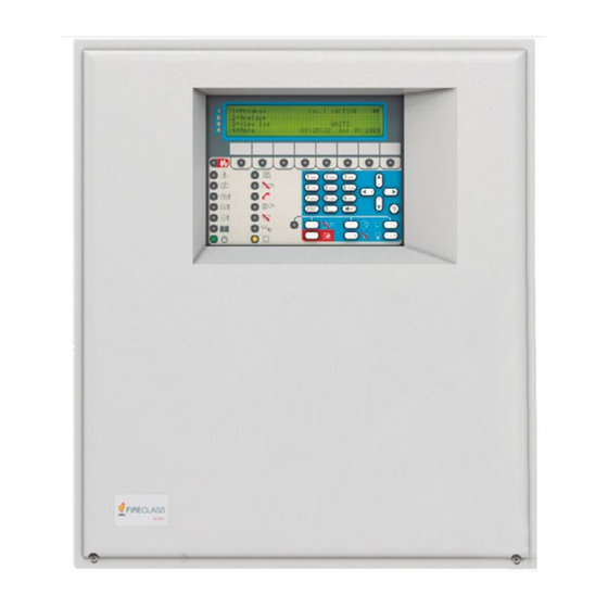
Reset will stop alarm, delay to alarm, warning, and fault conditions. Access to this command is limited to Figure 1: User interface view of FC503 and FC506 authorized personnel using an installer or user access code. The system reprocesses any alarm, delay to alarm, warning or fault signal that is not cleared by a reset. -
Page 6: Panel Command Keys
Panel command keys Table 3: Description of the control panel and repeater keys Description SILENCE/ RESOUND Restores the silenceable outputs and the loop devices to standby status SOUNDERS Note: The silence status remains until you press the SILENCE key again in day mode;... - Page 7 Table 5: Buzzer signaling Right No function Condition Frequency Sound Pause Left (Hz) System Fault 1300 2.5 s 2.8 s Figure 2: Example of the LCD display after pressing (main processor the Help key fail) General Fault (Programming data corrupted) Alarm 3300 0.2 s...
- Page 8 Figure 3: Event driven screens and MAIN screen basic Only if the panel is in interactions normal activity. No timeout for ANALYZE menu, VIEW LOG screen, VIEW LIST screen. The timeout can be extended to four minutes in the programming menu when you enter the parameters.
- Page 9 TROUBLE IMPORTANT: New batteries are required. (Amber) POWER ON ON indicates that the panel is supplied with power. OFF indicates a mains failure (Green) whereby both mains and battery power is lost (the battery disconnect threshold is 19.2 V). Power must be restored before the batteries reach the disconnect threshold.
- Page 10 The event log screen content and the enablement to display it are WAITS Panel is waiting to be set by the FC500 FC503/FC506 software (SW). For configured information about FRONT screen key functions, see Table 7. ————...
- Page 11 Disable, and Modify sections of screen, press and hold the 4 key. this manual. For installation information, refer to the FC503/FC506 Installation manual. Figure 5: Interaction between the diagnostic screens Event driven screens The event driven screens activate when the system detects events.
- Page 12 View list entry on the MAIN screen. Warning status You can program the FC503/ FC506 fire control panel to provide warning or delay to alarm status before alarm status. The warning status is signaled by the warning...
- Page 13 Table 13: Cursor key functions Function Shows the next event, other than the first and the last Down Shows the previous event, other than the first and the last Right Shows the next string of data Left Shows the previous string of data Table 14: ESC and ENTER key functions on the MAIN screen Function...
- Page 14 To supply the information about the points in delay Figure 9: Delay to Alarm status: Scrolling Right to alarm, the visualization of the delay to alarm is by zones (default) or by points. The following features signal the delay to alarm status: •...
- Page 15 Irrespective of which zone it belongs to; the last point Jumps to the zone status visualization in the Delay to Alarm field contains the information screen. about the last activated point. Note: To visualize, on the FC500 repeater, press the 1 key and also the ENTER key.
- Page 16 Figure 12: Display fault states Press the Left key to scroll back to the third block of data Press the Left key to scroll back to the second block of data Press the Left key to scroll back to the first block of data Table 20: ESC and ENTER key functions in the Delay to Alarm state...
- Page 17 If the last fault is related to a point, use the Press the Right key to 3 key to jump to the last activated Loop scroll to the second Device Status Visualization screen. block of fault zone data Press the Right key to If the last fault is a loop break fault, jump to scroll to the third block the Locate the Loop Break screen.
- Page 18 Note: During the locate loop break procedure all the detectors power down. At the end of the procedure, a full loop initialization is executed. The devices not in the configuration are not found. Locate the not addressed devices In the case of a NOT POGRAMMED DEV. fault, it is possible to locate all the unaddressed devices.
-
Page 19: View Log Parameters
Up, Down, Right, No functions Left This section provides an overview of the Return to the MAIN programming features on the FC503/FC506 panels. screen. For information on the parameters of each state, refer ENTER No function to the FC503/FC506 Installation Manual. -
Page 20: Key - View Devices
The Loop field displays the total current supplied to If blinking, the control panel is operating all three loops in real time. This field has a 5 second normally refresh rate. Module number 2 Key - View devices Overcurrent that powers OFF the loop Use the 2 key to view the loop device data (select the Current value in the 3... - Page 21 Figure 19: Viewing devices on the loop (detectors Fields and modules) The Device Status field displays the current status of the detector or module. The possible values are as follows: • WORKING • ACTIVE • WARNING • FAULT • ZONE DIS. •...
-
Page 22: Key - View Sw Zones
Use the 3 key (SW Zone) option in the Analyze menu to view software zones (maximum 128 zones for Figure 20: Viewing SW zones FC503 and 256 zones for FC506). The status of all the SW zones in the system is displayed in compact format, see Figure 20. -
Page 23: Key - View Network Devices
Standby status Open collector output 5 Key – View network devices Figure 23: Viewing the communicator Use the 5 key to view network devices such as MFI modules (maximum 4), client panels (maximum 7) and repeaters (maximum 8). See Figure Fields The Network devices field status displays the related output status using abbreviations. -
Page 24: Key - View The Log
If blinking, the control Selects the previously panel is operating available event normally Down Selects the next available Mode type event Right Displays the next available 8 Key – View the log data (see Figure Use the 8 key to select View Log or select it directly Left Displays the previous from STANDBY status. -
Page 25: Key - View The Fw Version
• Version of the PCB • Type of power supply on board • Type of batteries on board Figure 26: Scrolling with the Right key to view log • Presence of the auxiliary controller, see events Figure 27 Table 40: Alphanumeric, Cursor, ESC and ENTER key functions to view panel information Function Alphanumeric... - Page 26 the SW zone and loop device or the description of a system part and the related label. Table 42: Alphanumeric keypad, Cursor, ESC and ENTER key functions to view list information Function Displays the enablement screen and enables the displayed item Navigates the list;...
-
Page 27: Modify
Table 44: Key functions on the modify panel label MODIFY Function Alphanumeric Enter or update the panel label keypad To access the MODIFY menu, enter the user access • Cursor keys Up: changes the selected code (11111 at default), each digit will be masked by letter from lower case to * (asterisk). -
Page 28: Key - Day And Night Modes
the second screen in Figure 30 displays for 5 4 Key - Time and date seconds. To enter or change the control panel time and date, use the 4 key to select Time and Date in the MODIFY Figure 30: Display panel label menu (see Figure 32). -
Page 29: Key - Walk Test
Note: During the clear log activity the MAIN screen seconds. This zone setting is programmable displays with the panel activity field loaded with the using the PC software. The default value is NO. clear log string (see Figure 35). Once the log has The presence of a zone in the walk test mode is been cleared, the panel resets. -
Page 30: Disable
If blinking, the control DISABLE panel is operating normally To access the DISABLE menu from the MAIN Options screen, enter a user PIN password (the default PIN is 11111): each entered digit will be hidden with the * symbol. This activates the procedure used to enable Table 48: Keypad and key functions in the and disable each of the following: Disable state... -
Page 31: Key - Devices (Disable)
Access level Panel status Table 50: Alphanumeric keypad to select a list to If blinking, the panel is analyze operating normally Options to choose Function List type Shows the list of disabled zones List item information Shows the list of disabled loop devices Current item ID Shows the list of disabled system Number of items in the... -
Page 32: Disable Device On The Loop
• Figure 37: Displays of disable devices Right key: Selects the next loop • Left key: Selects the previous loop Cancels the operation Returns to the previous screen ENTER Confirms and displays the screen of the selected loop. Disable device on the loop To display the current status of the device, select the loop and then the device. -
Page 33: Disable Sw Zone
Table 60: Cursor, ESC and ENTER key Table 61: Keypad and key functions in the display functions to disable a device on the loop SW zone state Function • Function Cursor keys Up and Down keys: No Alphanumeric No function functions. -
Page 34: Key - Network
Figure 39: Display Dis. Outputs network device. Note: If the number is incorrect, an error message will be shown: WRONG VALUE PLEASE ENTER NEW PARAMETER. Cursor keys Use the Up Key to show the next type of network device. Use the Down Key to show the previous type of network device. - Page 35 • If the TEL i/f communicator has not been Cancels the operation enabled using software (options screen, Returns to the previous FireClass FC500 (FC501_FC503_FC506) screen. Console) and you attempt to enable/disable it, ENTER Confirms and displays the the following text appears on the display: next screen.
-
Page 36: Key - Fire Relay
Figure 42: Display enabled/disabled password 7 Key - Password disable This option is only enabled if you enter the control panel using a Master Installer PIN (Default 00000). Use the 7 Key to select the disable password option; after the option has been selected the corresponding password will be disabled/enabled (see Figure 43). -
Page 37: Key - Sounder (Disable)
activated with an access level 2 or 3 pass code. For more Figure 43: Display enabled/disabled fire information, see Table relay LCD display description The information on the LCD display is organized as screens. There are two screen types: • MAIN screen •... -
Page 38: Cpr Information
0051 Tyco Fire & Security GmbH, Victor von Bruns-Strasse 21, 8212 Neuhausen am Rheinfall, Schaffhausen, Switzerland DoP-2018-4260 (FC503/ FC506 with optional FC500IP module) EN 54-2:1997+A1:2006 EN54-4: 1997+A1:2002+A2:2006 EN 54-21: 2006 Control and indicating equipment with integrated power supply equipment for fire detection and fire alarm systems for buildings with alarm transmission and fault warning routing equipment.
Need help?
Do you have a question about the FC503 and is the answer not in the manual?
Questions and answers