FireClass FC501 Installation Manual
Addressable fire control panels
Hide thumbs
Also See for FC501:
- Installation manual (71 pages) ,
- Quick start setup manual (52 pages) ,
- Pc programming manual (32 pages)
Table of Contents
Advertisement
Quick Links
Advertisement
Table of Contents

Related Manuals for FireClass FC501


Summary of Contents for FireClass FC501
- Page 1 FC501 Addressable Fire Control Panels Installation Manual www.fireclass.net...
- Page 2 0051-CPR-0408 (FC500IP in FC501-L/FC501-H/FC501-HK) EN 54-21 NOTE- The FC501 Fire control panel can support several addressa- Alarm transmission and fault warning routing equipment for fire ble devices (Detectors, Modules, Manual call Points, etc). The pre- alarm systems installed in buildings.
-
Page 3: Table Of Contents
TABLE of CONTENTS INTRODUCTION Software window Look Control panel connections FC501 Fire Control Panel Main window Accessory Items Icons description Description File menu Input Tools menu Outputs Panel Details Operating Features Panel Details Menu Interface Communication Menu Access to Signalling and Commands... - Page 4 FC430SB - Loop Low Power Sounder Base 4B-I - Isolator Base FC490ST - Loop Service Tool FC410BDM - Beam Detector Module FC410CIM - Contact Input Module FC410DIM - Detector Input Module FC410RIM - Relay Interface Module Addressable Fire Panel FC501...
-
Page 5: Introduction
FC500REP This Repeater panel is intended for con- The FC501 Fire panel serie has been designed and nection (via 4 wires) to FC501 Control panels. It provi- manufactured to the highest standards of quality and des all the visual and audible warnings generated by performance adopted by Bentel Security. -
Page 6: Operating Features
Operating Features During Alarm status, (see Access to Signalling and Commands) it is possible: Warning The FC501 control panel can be program- Ø Access Level 2 stop the Silenceable outputs by med to provide WARNINGS or PREALARMS status be- pressing the Silence key ( fore ALARM status. - Page 7 Message Problem Switching 1 Fault Switching power supply Mains fault he Control panel is NOT powered from the Mains Battery The Control panel batteries charger not working properly Low battery The Control panel batteries are empty Earth Leakage to Earth 24A Output 24A Output is shorted 24R Output...
-
Page 8: Interface
(Prealarm) Alarm 0,2 s 0,2 s 3300 Hz Audible Signalling The Buzzer will signal the Control Fault 660 Hz panel status as in the following table 2: Table 2 Buzzer signalling Addressable Fire Panel FC501... -
Page 9: Access To Signalling And Commands
ONLY the Manufacturer should be allowed to repair or n Power Supply replace the PCB, (requires removal of the Cover screws). The power supply system of the FC501 Control panels complies with EN54-4. n Users and Installers Features All models are powered by the Mains (230V, 50 Hz): Ø... -
Page 10: Description Of The Fc500Rep Repeater Signalling
Night Mode after the Silence Time expires automatically the SILENCE will end. Test Glowing indicates Test conditions on at least one zone. MAINS OFF indicates Mains failure (230 V). (Green) IMPORTANT: Power must be restored before the batteries empty. Table 3 Description of the status LEDs Addressable Fire Panel FC501... -
Page 11: Description Of The Control Keys (Panel)
DESCRIPTION Lamp/Buzz This key can be used to test the buzzer and LEDs . If this key is pressed (when the Control panel is Test functioning as intended), all the LEDs will glow and the buzzer will emit a continuous beep. This key can be used to restore the Silenceable outputs to standby status. -
Page 12: The Status Led
Slow Blinking indicates that the corresponding Software zones is in Pre-Alarm status. CONTROLS ON Glowing indicates that the Control Panel is at least at level 2 so the Silence/Reso- (AMBER) und Sounders, Reset and Investigation Delay Keys are enabled Table 6 Description of the status LEDs Addressable Fire Panel FC501... -
Page 13: Parts Identification
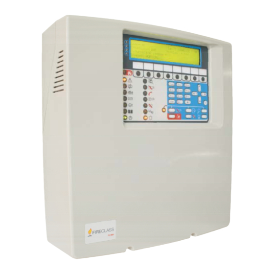
BATTERY BATTERY TEST TEST TROUBLE TROUBLE POWER ON POWER ON DAY MODE ON DAY MODE ON EVAC EVAC EVAC SILENCE BUZZER SILENCE BUZZER SILENCE BUZZER LAMP TEST LAMP TEST LAMP TEST FC501 Figure 1 FC501 Parts: external view PARTS IDENTIFICATION... -
Page 14: Description Of Parts
Description of Parts Description FC501 cover This section describes the components of the FC501 Knockouts for cables ducted externally Control panels. Display Screws (2) to close the Cover on Backplate Unless otherwise stated, the numbers in boldface in this Knockout for connection FC501-H Panel with Manual refer to the Tables and Diagrams in this section. - Page 15 Tubular spirit level Loop3 Connector for FC500IP Module RS232 Serial (PC link) Opening to insert the zone location text strip Hole for Main module fixing USB port FIRECLASS FC501 FIRE FIRE GENERAL FAULT GENERAL FAULT MORE INFO MORE INFO SOUNDERS...
- Page 16 250mA or less & the Auxiliary 24Vdc current exceeds 250mA or the Auxiliary 24V output current is 250mA or less. output current required is greater than 250mA. 42 43 Figure 4 BAQ35T24 and BAQ60T24 Switching-power-supply Addressable Fire Panel FC501...
-
Page 17: Installation
INSTALLATION Installing the Control panel Installation of this system must be carried out strictly in accordance with the instructions in this section, and in compliance with the local Work carefully through the following steps (see the Fi- safety regulations in force. gures 1 and 2). - Page 18 LOST DEVICE BUZZ TEST PRE-ALARM LOGIC UNIT SILENCE COMMUNICATOR COMMUNICATOR INVESTIGATE DAY MODE NAC FIRE OUTPUT SILENCE DISABLED HEARTH BUZZER SILENCE LOW BATTERY RESET NO BATTERY TEST FC500 EVACUATE MAINS MAINS Figure 5 Installation FC500REP Repeater Addressable Fire Panel FC501...
-
Page 19: Description Of The Terminals
n Telephone line 1. Lay the connection cables (refer to “Connecting Repeaters”). LE Terminals for connecting the external telephone line. 2. Remove the screws (68) (see Figure 5) and open the Repeater FC500REP. LI Terminals for connecting the internal telephone line: connect these terminals to other telephone devices that 3. -
Page 20: Audio Station
LEFT RIGHT LEFT RIGHT LEFT RIGHT FC501 + L3 -+ L3 - + L2 - + L2 - + L1 - + L1 - Figure 6 1) Wiring diagram of a 2-wire connection, a) Isolators; b) Compatible analogue devices (Fire detector, Input modules, Output modules, Manual callpoints);... -
Page 21: Auxiliary Outputs
LEFT RIGHT LEFT RIGHT LEFT RIGHT FC501 + L3 -+ L3 - + L2 -+ L2 - + L1 - + L1 - Figure 8 Wiring diagram of a 4-wire connection: a) Isolators; b) Compatible analogue devices (Fire detector, Input... -
Page 22: Rs485
ØPositive (27.6 V) on terminal [24R]; ØNegative on terminal [M]. +BAT- Terminals to connect the batteries inside the FC501 control panel. This power supply is disconnected during the reset of the Control Panel (about 2 s) so it is suitable for... -
Page 23: Connecting Repeater Fc500Rep
The maximum for all 3 loops is 128 addressable analo- time of the system. gue fire detectors and analogue devices (Input modu- As one control panel only is in the system all the Repea- les, Output modules). ters must be supplied by the control panel itself, unless a Power supply Station is in the system. -
Page 24: Connecting The Power Supply
3. Observing the battery polarity, connect the battery terminals to terminals -BAT+ on Main Board (wires supplied). 4. FC501-L use 7 or 12Ah @ 12 V YUASA batteries; FC501-H/FC501H-K use 12 or 38Ah @ 12 V YUASA batteries or similar with case flame class UL94-V2 (or higher). -
Page 25: Installing Fc500Ip Board
29,0 28,0 27,4 27,0 26,0 TEMPERATURE (°C) Figure 12 Switching Power Supply Output Voltage graph. To find the Output Voltage using the graph: — indicate the Probe temperature on the TEMPERATURE (°C) axis; draw a line from the temperature value point up to the curve a); draw a line from the intersection point across to the VOLTAGE (V) axis;... -
Page 26: Installing The 38Ah Battery Metal Box
Thermal probe (see Fig.13 and14) Work carefully through the following steps (see Figure 14), Flat cable for the connection with FC500IP for the FC501-H/FC501-HK fire panel only. Serial port RS 232 (PC LINK) Module IP (FC500IP) connector 1. Remove the two screws on the cover and open the metal box. - Page 27 Zona Zona Zona Zona Zona Zona Zona Zona Zona Zona LOOP1 LOOP2 B078-P0 LOOP3 NC NO NC NO J1 +NAC1 +NAC2 MIC SPKBLK RED OC1 Oc2 Figure 14 Control Panel (FC501-H/FC501-HK) and 38Ah Batteries metal Box connection (accessory item). INSTALLATION...
-
Page 28: Maintenance
Ø verify that the fault is reported correctly by the Fire Panel; Ø remove the connection previously made. PC-LINK Cable RS-232 Female Connector 4 way LOOP1 Fire panel Solder Side MTA Connector Board Figure 15 Schematic diagram of the PCLink cable Addressable Fire Panel FC501... -
Page 29: Pc Programming
(see Figure 16). “PROGRAMMING FROM THE PANEL” section. To ma- nage and program the FC501 control panel by a PC the Fi- Control panel connections reClass Console application must be installed on the PC. If you are using the Supervisory, Management, Downlo-... -
Page 30: Main Window
Control Panel. the programming/management of the fire system) Ø Click on this icon to select the Loop for inserting with FireClass console, so to open it just click on it. devices. Panel Details Ø Click on the icon to start operations in Real Time. -
Page 31: Panel Details Menu
Figure 20 Communication window. Figure 21 Account window. - Panel n Language Menu - Communication The Language menu allows you to change the system - Panel Language language (User Interface or Repeater) to any of the lan- - Firmware Update - Screen Saver guages currently loaded. -
Page 32: Account Menu
Help Menu Click on Help option; a technical support file will be opened. This application allows you the lear- ning and the use of FireClass Console. Programming Pages The programming pages of the system are: Figure 23 Detectors parameters programming Window... -
Page 33: Loop Wiring Calculation
Manual call Point can be associated with 1 of the alarm threshold will be modified accordingly (false available software zones (32 for FC501 control pa- alarms). nel). If a device goes into ALARM status, the zones it Ø... -
Page 34: Input Module Parameters Programming
4 of the 32 available sof- tware zones for FC501 panel. An Output module will be If a detector linked to an Output or Input-Output Mo- activated when any of the zones, where it is enabled, go dule, is disabled (remove a tick [3] in the proper sec- into ALARM status. -
Page 35: Multiple Input-Output Module - Parameters
DELAY (60s/30min) parameter, when set, applies to all sociated with 1 of the available software zones (32 smoke detectors assigned to the selected zone the alarm for FC501). verification algorithm as described in the EN54-2, (see Ø Led blinking: if this option is enabled, the Manual page 51). -
Page 36: Outputs Programming
Ø Backup PSTN line For the output OC1 ONLY, selec- each Output can be associated with up to 4 of the available software zones (32 for FC501 fire panel). ting this option and having a secondary communicator connected , in the case of malfunction of the PSTN, this In the TRIGGER POINTS section: each Output can be associated with 3 Input Points. -
Page 37: General Options Programming
Ø Relay FAULT Non-supervised Fault output. Dry Ø a click only the PSTN is present, but not enabled; contact relay for non-supervised devices. Ø a double click the PSTN is enabled. EN54-2 certification applies ONLY when FAULT When PSTN is enabled you can also select whether to output is not J (EN 54-1) type, therefore this output enable both events, alarm and fault or one of two. -
Page 38: Communicators Programming
Call Attempts which have been programmed. If the Call All Voice Messages numbers option is disabled, the PSTN Interface will interrupt the calls as soon as one is successful. Figure 29 Page to print the zones label. Addressable Fire Panel FC501... - Page 39 General options This section is used to select the Allows a voice message to be recorded via the mi- general options for the IP Module. crophone on the PC (max 6 sec., Header message 12 Encryption key – If it has been programmed, the IP sec.).
-
Page 40: Clock
Messages section. to load same voice messages in several panels) Load the label of the first 8 zones, which should be printed and inserted in the transparent window in the Addressable Fire Panel FC501... -
Page 41: Battery Calculation
Import the type of wiring (from a database) for use While the FC501 Console is in Real time mode, it con- in various connections Loop and so these type of wires stantly receives data from the panel, and provides the... - Page 42 At this point it is suffi- Disable The Disable page (click-on the right button on cient to drag the selected device in the relevant the selected device) is available only when the FC501 position on the map in question. Console communicates in Real Time.
-
Page 43: Programming From The Panel
The FC501 system can be managed from the User in- sequence and cyclically. terface (main panel) and/or through the FireClass Con- 1= ABC, 2= DEF, 3= GHI, 4= JKL, 5= MNO, 6= PQR, sole application. -
Page 44: Single Selection
Vocabulary area Cursor Entry area ESC Key: Use ESC key to cancel the operation and to step back to previous page. Figure 34 Assisted entry procedure ENTER key: Accepts the programmed string and the Addressable Fire Panel FC501... -
Page 45: Main Page - Accessing The System
Control panel Name of Control Panel Access Level Status working properly Current phase Control Panel name (It can be modified by User) FC501 Panel lev.3: PROGRAM 1=Analyze lev.1 : ACTIVE INSTALLER MASTER PANEL Insert the Password 3=View Log SCANNING LOOP... -
Page 46: Programming Page
Control panel status control panel for the installer 1 (Main Installer) and 9 for the next one. Access Level working properly Control Panel name FC501 Panel lev.3 : PROGRAM INSTALLER 1 Modify any Installer Password [_____] Field to insert password FC501 Panel lev.3... -
Page 47: Automatic Zones Assignment
Control Panel name Access Level From address 49 to address 64 assigned to zone 4 From address 65 to address 80 assigned to zone 5 FC501 Panel lev.3: PROGRAM From address 81 to address 96 assigned to zone 6 ENROLLING IN PROGRES... -
Page 48: Auto Addressing Procedure
The Auto addressing procedure is part of the loop devi- The control panel is ready to work, at this time, ces enroll process in the FC501 panel. The loop devi- (with the default basic programming) ces enroll process is initiated by the installer:... -
Page 49: Key -Device
Sounder Sounder Sounder Sounder Addressable Addressable Addressable Addressable Callpoint Generic Module DDM Module FC501 panel lev 3: PROGRAM Name of Master Panel Remove device? Remove device? Remove device? Control Panel Choose loop Loop 1 Name selected [ L1 ] L2... -
Page 50: Choose The Device
This option (Remote LED) will be possible to pro- Regarding the figure 43, the “selected device” field gram also on FireClass Console, in the program- shows the currently selected device. The “Add ” field is used to enter the address of the selected device. The ming page of the detectors. -
Page 51: Key - Sw Zone
Output the panel works Status Number properly Control Panel name Access Level FC501 Panel lev. 3: PROGRAM SC Output: 001 FC501 Panel lev. 3: PROGRAM Up or Down to select the type SC Output: 001 Enter the SC Output number... -
Page 52: Key- Output
MASTER Panel Time Type done 000/002 001> 00: 19.50 L2:001< enter the address 00: 19.50 Symbol show the selected module to enable Figure 48 Display to enable the FC500FMI module Figure 49 Display "on demand device mapping" Addressable Fire Panel FC501... -
Page 53: Key - Map Device
Status properly Access Level ESC key The ESC key: to end the mapping procedure and exit. FC501 Panel lev.3 : PROGRAM USB activities 0=Extra ENTER key the ENTER key: to confirm the entered ad- 1=Load Audio 2=Save audio 3=Load program dress value. - Page 54 Figure 52 The scheme in the figure displays the LCD pages sequence required by this feature: "Language strings download during panel run time" mory (previously downloaded from the CD supplied with the panel or from the FireClass site), see the dia- POWER ON gram of operation in figure 52.
-
Page 55: Key -System
USB stick connected to overlap). In sequence: the control panel before first Power up. -PANEL TYPE (FC501-L/FC501-H) -BATTERY TYPE (7Ah/12Ah/38Ah This loaded language will be the language of the control panel. If the USB stick is not present at the first panel... -
Page 56: Fc500Rep Repeater Address From The Repeater Panel Only
FC500IP module, the procedure to Restore factory Default (key 9) will have no effect on the FC500IP After the FC501 control panel has been connected, at module. To restore the FC500IP module to factory the first start-up the FC500REP will verify the presence default use the procedure of the FireClass Conso- of the address and its conformity. -
Page 57: Quick Start-Up Procedure
QUICK START-UP PROCEDURE This procedure allows the quick start-up of the FC501 This procedure is divided into three main phases: fire detection system. 1 Auto-learning When the loops are wired, electrically verified and all 2 Auto- addressing the devices have been installed in to the loop, it is pos- 3 Device Mapping sible to connect the loops terminals to the panel. - Page 58 FC501 Panel lev.3 :PROGRAM 1=Auto 2=Device 3=SW Zone 4=Output 5=Network 6=Map. Dev. 7=USB 8=System 9=Default 0=L3 PWD Differences found! 1: Accept new configuration Add new devices Discard changes AUTO ENROLLING Automatic zones assignment 1 = on loop basis 2 = on device address basis...
- Page 59 MESSAGE Not addressed devices LOOP PANEL Automatic zones Differences found! found assignment start autoaddressing ? All devices not DEFAULT addressed Some devices (Applicable only to the addressed already addressed DEFAULT devices) Some devices not addressed All devices DEFAULT addressed Fully addressed CONFIGURED Same configuration (Applicable only to all...
-
Page 60: System Default
The previous zone assignment schemes are applied also to the first "trigger zone" in the case of output only devices(sounder, beacon, SNM module,…) or output channel of Input/output devices. Addressable Fire Panel FC501... - Page 61 CO+Smoke+Temperature detector default values Input Channels Enablement Enabled Label See note (**) Channel Label See note (**) Enablement Enabled Led blink Assigned zone Address related Assigned zone (see: "Zone assignment) (see: "Zone assignment) Base type Normal Use zone setting Use zone setting Day algorithm Universal TSM module...
- Page 62 Selection Call attempts Iteration Call all telemonitoring numbers Call all voice message numbers Telephone number label TEL. NUMBER xx(*****) All Telephone numbers behavior None Trigger events Panel alarm, Panel Fault Message #1 to #7 Pre recorded Addressable Fire Panel FC501...
-
Page 63: Accessory
ACCESSORY FC460P or FC400P - Addressable Optical The following is a list of accessories for FC501 control Smoke panel, with a description of the main features. For fur- ther information about these accessories, please refer The FC460P/FC400P optical smoke detector forms... -
Page 64: Fc460Pc Addressable Optical Smoke & Heat Detector & Co
The type of alarm generated by the callpoint is tional immunity to false alarms. configured in FireClass Console.The FC420CP call po- The functionalities of the FC460PC detector are: int meets the requirements of EN54 Pt.11. The... -
Page 65: Fc490St - Loop Service Tool
FC490ST - Loop Service Tool The relay is controlled by a command sent from the FC fire controller via the addressable loop. The relay state The FC490ST Loop Service Tool is used to program (activated, deactivated or stuck) is returned to the con- the loop address into FC addressable devices. -
Page 66: Mp69-Duct Probe Unit
Sounder/ Sounder-Beacons are designed to be driven by the local National Standard. As a guide a common from a FC501 control panel via the addressable loop. lateral distance of 7.5m will be used in this guide. Use The FC410LPBS Series of sounders/sounder beacons... -
Page 67: Fc430Lpbsb Loop Powered Addressable Sounder/Beacon Base (En54-23)
FC501 control panel via the addressable loop. munication with a panel, loop power monitoring), which Tone, volume and flash rates are set in FireClass Console. enables the fire door to be closed when communication The sounder has four volume settings ‘High’ (90dB ±3), with a panel is lost for longer than 45s (±5s) or the loop... - Page 68 The module has an integral loop isolator. If this activa- tes a yellow LED illuminates. The activation remains in place until the short is removed. Addressable Fire Panel FC501...
-
Page 69: Specifications
500 mA. battery and associated circuitry Temperature range -5 to +40°C Storage -40 to +80°C Temperature Operating Humidity Up to 95% non-condensing Dimensions 335*369*115 mm (W*H*D) Weight 3 Kg (without batteries) Table 10 FC501 Technical features SPECIFICATIONS... -
Page 70: Table Of Distribution Of Currents
Table of distribution of currents FC501-L CONTROL PANEL SWITCHING POWER SUPPLY BAQ35T24 (Imax=1500mA) = (7x0.8)/24=233mA -> 250mA Load 80% in 24h = 1500-250=1250mA for panel Panel load distribution =175mA electronic 7 Ah BATTERY = 200mA à 313mA @Vbattery LOOPs @40V... - Page 71 TERM. DESCRIPTION v(V) i(A) MAIN BOARDS +L1- (+)Loop 1-Positive signal, left side. — — LEFT (-)Loop 1-Negative signal (return), left side +L1- (+)Loop 1-Positive signal, right side. — — RIGHT (-)Loop 1-Negative signal (return), right side +L2- (+)Loop 2-Positive signal, left side. —...
- Page 72 © FireClass via Gabbiano 22, Z. Ind. S. Scolastica 64013 Corropoli (TE), Italy Hillcrest Business Park Cinderbank Dudley West Midlands DY2 9AP United Kingdom www.fireclass.net ISTISFKEFC501 3.0 070114 V10...
Need help?
Do you have a question about the FC501 and is the answer not in the manual?
Questions and answers