FireClass FC501-L User Manual
Fc501 series addressable fire control panel
Hide thumbs
Also See for FC501-L:
- Quick start setup manual (52 pages) ,
- User manual (41 pages) ,
- Installation manual (88 pages)
Table of Contents
Advertisement
Quick Links
Advertisement
Table of Contents

Related Manuals for FireClass FC501-L


Summary of Contents for FireClass FC501-L
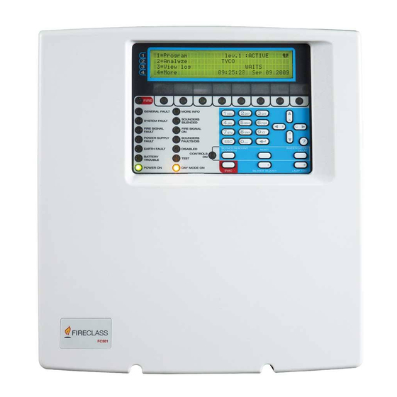
- Page 1 FC501 Addressable Fire Control Panels User Manual www.fireclass.net...
- Page 2 This Fire Control panel can be programmed only using Maintenance the Software FireClass Console release 1.0 or higher. To ensure that the system continues to operate nor- mally it must be maintained with regular testing by the Control panel FW ver. 1.0 or higher.
-
Page 3: Table Of Contents
TABLE OF CONTENTS INTRODUCTION MODIFY FC501 Fire Control Panel MODIFY MENU Accessory items 1 KEY -INIT MSG (Modify panel label) User Access Level 2 KEY - User Password Insert or Modify Password 3 KEY-DAY/NIGHT Day/Night Mode USER INTERFACE 4 Key-Time and Date Description of Keys 5 Key- Clear LOG Panel Command keys description (Table 1) - Page 4 ZONE ZONE ZONE ZONE ZONE ZONE ZONE ZONE FIRE GENERAL FAULT MORE INFO SOUNDERS SYSTEM FAULT SILENCED FIRE SIGNAL FIRE SIGNAL FAULT POWER SUPPLY SOUNDERS FAULT FAULTS/DIS SILENCE/RESOUND INVESTIGATION EARTH FAULT DISABLED RESET SOUNDERS DELAY CONTROLS BATTERY TEST TROUBLE POWER ON DAY MODE ON EVAC SILENCE BUZZER...
-
Page 5: Introduction
FC500REP Repeater Repeaters are peripherals that The FC501 is available in the following models: Ø FC501-L - Addressable Control Panel with 3 different provide all the system status information, emit audible signals and allow users to control the functions of the... -
Page 6: User Interface
USER INTERFACE n Silence/Resound/Sounders Description of Keys The control panel can operate in DAY or NIGHT Mode. To manage the panel from the User interface the follow- If the system is silenced during DAY Mode, SILENCE ing controls are used: status will be held until the system is unsilenced (i.e. -
Page 7: Key Help
Key Help To manage the brightness and contrast of the LCD display see MAIN page. To explain the information on the LCD display in the different pages, an embedded help feature is present on the panel n Buzzer (Audible Signals) LCD display. - Page 8 ICON DESCRIPTION FIRE Glowing indicates Alarm status. In the event of an Alarm, the Control panel will activate the (Red) unbypassed alarm outputs. SOFTWARE Glowing indicates that the corresponding Software zone is in Alarm status (*). ZONES Slow Blinking indicates that the corresponding Software zone is in Delay to Alarm status. (Red) (1-8) OFF indicates no alarms, The zone is in stand-by status.
-
Page 9: Front
Ø Selected language be re-activated downloading into the panel a new Ø Panel Identification number front page using the FireClass Console SW (see Ø The panel type (FC501-l/FC501-H) Screen saver Menu in the Installation Manual) Ø The installed battery capacity (7Ah/12Ah/38Ah) -
Page 10: The Event Driven Pages
The 3 key shows the panel View log or moves the If it blinks Control panel status indicates the panel to the Modify mode. First Warning Warnings Number Control panel operating normally The 4 key selects between the function groups related Total :0015 Status: Warning to the keys 1,2,3. -
Page 11: Delay To Alarm Status
Total :0015 status:WARNING Zones:004 / Dev.: 013 ALARM+DLY First zone: R-D department EVAC. First Z001 det.: office 3, south wing Last zone: Air compressor zone=456 Last Z001 det.: main corridor, north #0011 : zone: Boiler room zone=245 4= view all Push the right key to scroll Push the left key Push the right key to scroll... -
Page 12: Alarm Status
The EN54-2 requires that at the least, the first zone Zones:004 / Dev.: 013 ALARM+DLY First Z001 det.: office 3, south wing in Delay to Alarm, the most recent zone in Delay to Last Z001 det.: main corridor, north Alarm and the number of zones in Delay to Alarm 4= view all will be displayed. -
Page 13: Fault Status
Ø blinking the specific FAULT LEDs, if present Alphanumeric keypad For the alarm by ZONES or by POINTS the use is the same: (POWER SUPPLY FAULT - BATTERY TROUBLE- 1 key: to jump to the Zone status visualization page; EARTH FAULT-SYSTEM FAULT-FIRE SIGNAL FAULT- SOUNDERS FAULT/DIS). -
Page 14: Locate Loop Break Pages
n Locate loop break pages Use the 4 key to display further faults. When a point fault is present in the fourth row, a further From paragraph Fault status - 2 Key. 4 key press will cause the User Interface jump to the re- These pages are used to manage the “locate loop lated loop device status visualization page. -
Page 15: View-Log-Parameters
VIEW-LOG-PARAMETERS Read through the following section carefully to get an In this phase: overall view of how to use the Programming for the Us- Alphanumeric keypad Use the Alphanumeric keypad ers. For details regarding the parameters of each to select the different viewing functions: phase, refer to the respective paragraph in the “PRO- 1= Loop: start the procedure for selection and viewing GRAMMING FROM A PC”... -
Page 16: Key - View Loop
1 KEY - View Loop 2 KEY - View Devices Use the 1 Key to view the Loop data (see Figure 17). Use the 2 Key to view the Loop devices (see Figure 18). In this page: Select the Loop and then the device. n View of Loop Details n Select the Loop In this phase:... -
Page 17: View Device Data On The Loop
Control panel status if it blinks the panel n View device data on the Loop Control panel name is operating normally Access level Select the Loop and then the device, the Display will FC501 panel lev.1 : ANALYZE show Figure 20. Master Control panel Choose Loop Loop 1... -
Page 18: Key- View Sw Zone
3 KEY- View SW Zone 4 KEY- View Output The 3 Key (SW Zone) option in the ANALYZE menu ac- The 4 key Output option in the ANALYZE menu acti- tivates the viewing of the software zones (max 32). Dur- vates the viewing of the Outputs. -
Page 19: Key- View Network
5 KEY- View NETWORK 6 KEY- COMMUNICATORS Use the 5 Key to view the Network devices: MFI mod- The 6 Key is used to view the Communicator connected ules (max 4) and Repeaters (max 4) (see Figure 23). to the control panel, see Figure 24. In addition to the Firmware version, the FC500IP module status and the The field Network devices status displays the related address will be displayed. -
Page 20: Key- View Option
7 KEY- View Option View Log The 7 Key activates, in the ANALYZE MENU, the view- From MAIN page directly, the User, without password, ing of programmed system options, see Figure 25. The can arrive to View Log see Figure 26. status of the DAY/NIGHT MODE options will be indi- cated using the following abbreviations: The Event Class field displays the class of the event... -
Page 21: Key - View Fw Version
0 Key-Panel Total :0297 status: VIEW LOG Event :0292 RESTORE MS:Loop 2 det191 zone=002 By pressing the 0 key, in the ANALYZE menu, it is pos- 08:43:11 - 01/01/07 sible to read: Push the right key to scroll - the fire panel ID the second block of data regarding the zones in the LOG - the serial number of the Fire Panel (displays the elec-... -
Page 22: View Lists
View Lists Cursor Keys The UP Key, used to navigate the list, displays the next element; Directly from the MAIN page, press 4 =MORE Key and The Down Key, used to navigate the list, displays the then 2= View Lists. previous element;... -
Page 23: Modify
MODIFY MODIFY MENU 1 KEY -INIT MSG (Modify panel label) For the MODIFY option, from the MAIN page, press the Use the 1 Key to enter or update the Panel label. 3 key. In this phase: Alphanumeric keypad The Alphanumeric keypad is To access the MODIFY Menu: used to enter or update the panel label. -
Page 24: Key - User Password
2 KEY - User Password 3 KEY-DAY/NIGHT Use the 2 key to Modify the User Password (see Figure If the 3 Key is pressed, it is possible to change the con- 32). trol panel operating mode: Day mode or Night mode. n Insert or Modify Password The Day/Night mode will be toggled at each key 3 Select the option MODIFY, the display will show Figure... -
Page 25: Key-Time And Date
4 Key-Time and Date 5 Key- Clear LOG Use the 4 Key to select TIME and DATE in the MODIFY Use the 5 key to select Clear LOG (see Figure 35). menu to enter/change the control panel Time and Date (see Figure 34). -
Page 26: Key- Walk Test
6 KEY- WALK TEST Alphanumeric keypad Use to enter the SW zone number. The Walk Test option of the MODIFY menu will activate the zone programming procedure for the Zone walk test Cursor Key No function is related to the UP and Down (see Figure 36). -
Page 27: Disable
DISABLE To access the DISABLE menu from the MAIN page, The display (see Figure 18) shows how to select the de- you will be asked to enter a “User PIN” password (the vices to Disable/Enable. default PIN is 11111): each entered digit will be hidden with the * symbol. -
Page 28: Key - Disable List
1 Key - Disable list 2 Key - Devices (Disable) Use 1 key, or from MAIN page use 4 key (More) and then Use the 2 key to select “Device” Disable. The Loop can be 2 to select “View List”; (see Figure 38) In this phase: selected (see Figure 39). -
Page 29: Key - Sw Zone
3 Key - SW zone ENTER key Use the ENTER key to confirm and dis- able the detector.The User Interface moves to the MAIN page signaling a local programming activity fol- Use the 3 key to select “SW zone”; after the zone has been lowed by a panel reset. -
Page 30: Disable Sw Zone
n Disable SW Zone The display shows the current status of the Output, the The display shows the current status of the SW Zone, the possible actions are: ENABLE or DISABLE. possible actions are: ENABLE or DISABLE. In this phase: Alphanumeric keypad No function is related to Al- Alphanumeric keypad No function is related to Al- phanumeric keypad. -
Page 31: Key - Communic. (Disable)
If the TEL i/f communicator has not been enabled us- shown: NO ACTION TO BE DONE ing software (Options page- FireClass Console ) and you attempt to enable/disable it, the following text will Cursor Keys Use the UP Key to show the next type of appear on the display: NO ACTION TO BE DONE Telecom module. -
Page 32: Key-Password (Disable)
7 Key-Password (Disable) 8 Key - Fire Relay This option is enabled only if you enter in the Control Use the 8 key to select “Fire Relay”; the “Fire Relay” Panel using a Master Installer PIN (Default 00000). output can be Disabled/Enabled (see Figure 45). The Key 7 is used to select the Disable Password op- tion, after the option has been selected the correspond- The field “Current enablement status”... -
Page 33: Repeater Fc500Rep Signalling
EVENT DRIVEN PAGES Repeater FC500REP Signalling PREALARM ALARM PAGE FAULT PAGE WARNING PAGE WALK TEST PAGE PAGE n Description of command Keys ONLY the Lamp/Buzz/Test, Silence Buzzer and Evacuate Control keys can be activated without pass- word (access level L1). All other Control keys can be activated with password (access level L2 and L3) see MAIN PAGE Table 4. - Page 34 FIRE FAULT LAMP MORE ALARMS LOST DEVICE BUZZ TEST PRE-ALARM LOGIC UNIT SILENCE COMMUNICATOR COMMUNICATOR INVESTIGATE DAY MODE NAC FIRE OUTPUT SILENCE HEARTH DISABLED BUZZER SILENCE LOW BATTERY RESET NO BATTERY TEST FC500 EVACUATE MAINS MAINS Figure 46 Repeater FC500REP User Interface. DESCRIPTION FIRE Glowing indicates Alarm status.
- Page 35 Figure 47 Structure of the User Interface operations at L1and L2 levels. DISABLE...
- Page 36 0051 Tyco Fire & Security GmbH Victor von Bruns-Strasse 21 8212 Neuhausen am Rheinfall Switzerland DoP-2015-4211 (FC500IP in FC501-L/FC501-H/FC501-HK) EN 54-21 Alarm transmission and fault warning routing equipment for fire alarm systems installed in buildings. EN 54-21 ESSENTIAL CHARACTERISTICS © FireClass...
Need help?
Do you have a question about the FC501-L and is the answer not in the manual?
Questions and answers