
Subscribe to Our Youtube Channel
Related Manuals for Beckhoff EJ6910


Summary of Contents for Beckhoff EJ6910
- Page 1 Operating Instructions | EN EJ6910 TwinSAFE Logic Module 2023-03-10 | Version: 2.0.0...
-
Page 3: Table Of Contents
In operation ........................ 13 2.3.3 After operation........................ 14 3 TwinSAFE System Description ...................... 15 Extension of the Beckhoff I/O system with safety functions ............ 15 Safety concept .......................... 15 EtherCAT plug-in module system (EJ) .................... 16 4 Product description .......................... 17 EJ6910 - TwinSAFE logic module.................... - Page 4 5.10 TwinSAFE SC - configuration ...................... 95 5.11 Customizing / disabling TwinSAFE groups .................. 99 5.12 Saving the analog group inputs persistently ................. 102 5.13 Project design limits of EL6910/EJ6910.................. 103 5.14 Sync-Manager Configuration ...................... 103 5.15 TwinSAFE reaction times ...................... 106 5.15.1...
-
Page 5: Notes On The Documentation
Notes on the documentation Disclaimer Beckhoff products are subject to continuous further development. We reserve the right to revise the operating instructions at any time and without prior announcement. No claims for the modification of products that have already been supplied may be made on the basis of the data, diagrams and descriptions in these operating instructions. -
Page 6: Limitation Of Liability
Modifications and changes to the hardware and/or software configuration that go beyond the documented options are prohibited and nullify the liability of Beckhoff Automation GmbH & Co. KG. The following is excluded from the liability: •... -
Page 7: Documentation Issue Status
The original documentation is written in German. All other languages are derived from the German original. Product features Only the product properties specified in the current operating instructions are valid. Further information given on the product pages of the Beckhoff homepage, in emails or in other publications is not authoritative. EJ6910 Version: 2.0.0... -
Page 8: Staff Qualification
• Independently identify, avoid and eliminate sources of hazard. • Apply relevant standards and directives. • Implement specifications from accident prevention regulations. • Evaluate, prepare and set up the workplaces. • Evaluate, optimize and execute work independently. Version: 2.0.0 EJ6910... -
Page 9: Safety And Instruction
Notes are used for important information on the product. The possible consequences of failure to observe these include: • Malfunctions of the product • Damage to the product • Damage to the environment Information This sign indicates information, tips and notes for dealing with the product or the software. EJ6910 Version: 2.0.0... -
Page 10: Beckhoff Support And Service
The employees support you in the programming and commissioning of sophisticated automation systems. Hotline: +49 5246/963-157 E-mail: support@beckhoff.com Web: www.beckhoff.com/support Training Training in Germany takes place in our training center at the Beckhoff headquarters in Verl, at subsidiaries or, by arrangement, at the customer's premises. Hotline: +49 5246/963-5000 E-mail: training@beckhoff.com Web: www.beckhoff.com/training... -
Page 11: For Your Safety
Products marked with a crossed-out waste bin must not be disposed of with domestic waste. The device is considered waste electrical and electronic equipment when it is disposed of. Observe the national regulations for the disposal of waste electrical and electronic equipment. EJ6910 Version: 2.0.0... -
Page 12: Safety Image Signs
For your safety Safety image signs On Beckhoff products you will find attached or lasered safety pictograms, which vary depending on the product. They serve to serve to ensure safety for people and to prevent damage to the products. Safety pictograms must not be removed and must be legible for the user. -
Page 13: General Safety Instructions
TwinSAFE components comply with the requirements of the applicable electromagnetic compatibility standards with regard to interference emission and immunity. If you exceed the limits for emitted interference specified in the standards, the function of the TwinSAFE component may be impaired. EJ6910 Version: 2.0.0... -
Page 14: After Operation
De-energize and switch off components before working on them Check all safety-relevant equipment for functionality before working on the TwinSAFE component. Secure the working environment. Secure the machine or plant against being inadvertently started up. Observe the chapter Decommissioning [} 115]. Version: 2.0.0 EJ6910... -
Page 15: Twinsafe System Description
Extension of the Beckhoff I/O system with safety functions The TwinSAFE products from Beckhoff enable convenient expansion of the Beckhoff I/O system with safety components, and integration of all the cabling for the safety circuit within the existing fieldbus cable. Safe signals can be mixed with standard signals as required. -
Page 16: Ethercat Plug-In Module System (Ej)
The EtherCAT plug-in modules and the plug level for sensors and actuators can be placed flexibly on the signal distribution board. Signal distribution boards can be user-developed or provided as custom solutions by Beckhoff Automation GmbH & Co. KG. Fig. 1: EtherCAT plug-in module system (EJ) Version: 2.0.0... -
Page 17: Product Description
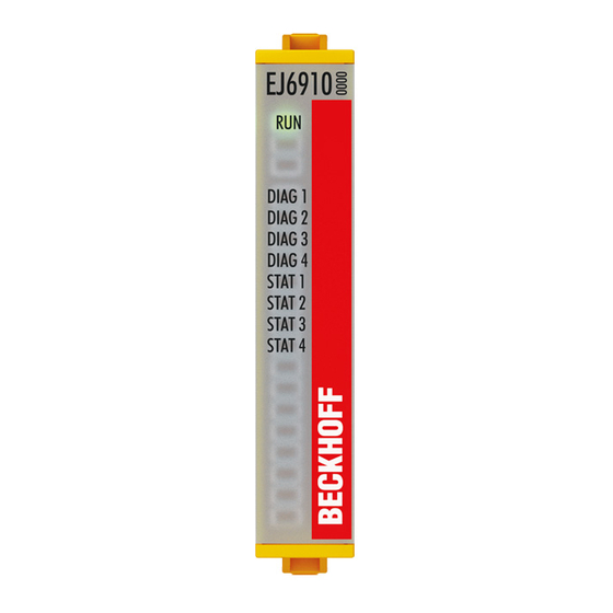
EJ6910 - TwinSAFE logic module The TwinSAFE logic EJ module is the link unit between the TwinSAFE input and output modules. The EJ6910 module meets the requirements of IEC 61508:2010 SIL 3 and DIN EN ISO 13849-1:2016-06 (Cat 4, PL e). Fig. 2: EJ6910 - TwinSAFE logic module EJ6910 Version: 2.0.0... -
Page 18: Intended Use
TwinSAFE EJ modules may only be used for the purposes described below! The TwinSAFE EJ modules expand the application range of the Beckhoff EtherCAT system by functions that enable it to be used in the field of machine safety as well. The TwinSAFE EJ modules are designed for machine safety functions and directly associated to industrial automation tasks. -
Page 19: Technical Data
Therefore, keep as large a distance as possible from the maximum values. Non-observance can endanger safety. The current certificates of all TwinSAFE products with the underlying standards and directives can be found at https://www.beckhoff.com/en-en/support/download-finder/certificates-approvals/. Product designation EJ6910 Number of inputs... -
Page 20: Safety Parameters
Element classification Type B 1. Special proof tests over the whole service life of the EtherCAT EJ6910 module are not required. 2. Classification according to IEC 61508-2:2010 (see chapters 7.4.4.1.2 and 7.4.4.1.3) The EtherCAT EJ6910 module can be used for safety-related applications as defined in IEC 61508:2010 up to SIL3 and DIN EN ISO 13849-1:2016-06 up to Cat 4, PL e. -
Page 21: Dimensions
Product description Dimensions Fig. 3: EJ6910 - dimensions Width: 12 mm Height: 66 mm Depth: 55 mm EJ6910 Version: 2.0.0... -
Page 22: Operation
Please ensure that the digital TwinSAFE components are only transported and stored under the specified environmental conditions (see technical data). 5.2.3 Mechanical installation WARNING Risk of injury! Bring the bus system into a safe, de-energized state before starting installation, disassembly or wiring of the devices! Version: 2.0.0 EJ6910... - Page 23 Operation 5.2.3.1 Control cabinet / terminal box The TwinSAFE EJ modules must be installed in a control cabinet or terminal box with IP54 protection class according to IEC 60529 as a minimum. EJ6910 Version: 2.0.0...
-
Page 24: Fig. 4 Installation Position And Minimum Distances
The temperature measurement consists of an EJ1100 EtherCAT coupler, to which EJ modules are attached, based on the typical distribution of digital and analog signal types at a machine. On the EJ6910 a safety project is active, which reads safe inputs and enables safe outputs during the measurement. -
Page 25: Electrical Installation
EJ Bus Coupler can provide. 5.2.4.2 Overvoltage protection If protection against overvoltage is necessary in your plant, provide a surge filter for the voltage supply to the Bus Terminal blocks and the TwinSAFE EJ modules. EJ6910 Version: 2.0.0... -
Page 26: Configuration Of The Ej6910 In Twincat
Configuration requirements Configuration of the TwinCAT Safety PLC requires TwinCAT automation software version 3.1 build 4020 or higher. The current version is available for download from the Beckhoff website at www.beckhoff.de. TwinCAT support The TwinCAT Safety PLC cannot be used under TwinCAT 2. -
Page 27: Adding An Ej6910
Operation 5.3.2 Adding an EJ6910 The EJ6910 TwinSAFE logic module is added in the same way as any other EtherCAT device. Open Safety Terminals in the list, then select the EJ6910 module. Fig. 5: TwinCAT - adding an EJ6910 Size of the process image The process image of the EJ6910 TwinSAFE logic module is adjusted dynamically, according to TwinSAFE configuration created in TwinCAT 3. -
Page 28: Address Setting On The Twinsafe Ej Modules With 1023 Possible Addresses
TwinSAFE addresses between 1 and 1023 are available. DIP switch Address 1023 WARNING TwinSAFE address Each TwinSAFE address may only be used once within a network / a configuration! The address 0 is not a valid TwinSAFE address! Version: 2.0.0 EJ6910... -
Page 29: Creating A Safety Project In Twincat 3
In the TwinCAT Safety Project wizard you can then select the target system, the programming language, the author and the internal project name. Select the setting Hardware Safety PLC as the target system and the graphical editor as the programming language. The author and the internal project name can be freely selected by the user. EJ6910 Version: 2.0.0... -
Page 30: Fig. 9 Twincat Safety Project Wizard
Fig. 10: Selecting the Target System node Set the target system to EJ6910 via the drop-down list and link it with the EJ6910 module via the Link button next to Physical Device. If online ADS access to the terminal is possible, the software version, serial number, online project CRC and hardware address (DIP switch) are automatically read from the module. -
Page 31: Fig. 11 Starting The Automatic Import From The I/O Configuration
The connection- and device-specific parameters are set via the alias devices. Fig. 11: Starting the automatic import from the I/O configuration If the automatic import is started from the I/O configuration, a selection dialog opens, in which the individual terminals to be imported can be selected. EJ6910 Version: 2.0.0... -
Page 32: Fig. 12 Selection From The I/O Tree
Fig. 13: Creating alias devices by the user 5.3.4.5 Parameterization of the alias device The settings can be opened by double-clicking on the Alias Device in the safety project structure. Version: 2.0.0 EJ6910... -
Page 33: Fig. 14 Alias Device In The Safety Project Structure
Check Conn ID must be unique within a configuration. Duplicate connection IDs result in an error message. Mode FSoE master: EL6910/EJ6910 is FSoE master for this device. Check FSoE slave: EL6910/EJ6910 is FSoE slave for this device. EJ6910 Version: 2.0.0... -
Page 34: Fig. 17 Selecting An Alias Device
TwinCAT function blocks for TwinSAFE Logic terminals. The EL6910/EJ6910 support activation of a ComErrAck at each connection. If this signal is connected, the respective connection must be reset after a communication error via the signal ComErrAck, in addition to the ErrAck of the TwinSAFE group. -
Page 35: Fig. 18 Safety Parameter For The Device
Safety Parameters tabs are identical to other alias devices. Fig. 19: AX5000 safety drive functions The General AX5805 Settings tab can be used to set the motor string and the SMS and SMA functions for one or two axes, depending on the added alias device. EJ6910 Version: 2.0.0... -
Page 36: Fig. 20 Ax5000 Safety Drive Options - General Ax5805 Settings
The parameter list corresponding to the safety function can be shown; in addition, an optional diagram of the function can be shown. At present the diagram is still static and does not show the currently selected values. Version: 2.0.0 EJ6910... -
Page 37: Fig. 22 Ax5000 Safety Drive Options - Function Diagram
5.3.4.7 External connection An external Custom FSoE Connection can be created for a connection to a further EL69x0, EJ6910, KL6904 or third-party device. If a dedicated ESI file exists for a third-party device, the device is listed as a selectable safety device, and the Custom FSoE Connection option is not required. -
Page 38: Fig. 23 Creating An External Connection (Custom Fsoe Connection)
Once the size is selected, the individual signals within the telegram can be renamed, so that a corresponding plain text is displayed when these signals are used in the logic. If the signals are not renamed, the default name is displayed in the editor (Safe Data Byte 0[0], …). Version: 2.0.0 EJ6910... -
Page 39: Fig. 25 Renaming The Individual Signals Within The Telegram
Fig. 26: Selecting the variables This can be a PLC variable, for example, which is then forwarded to the remote device or can be linked directly with the process image of an EtherCAT Terminal (e.g. EL69x0 or EL6695). EJ6910 Version: 2.0.0... -
Page 40: Fig. 27 Direct Linking With The Process Image Of An Ethercat Terminal
Fig. 27: Direct linking with the process image of an EtherCAT Terminal Further information can be found in the TwinCAT documentation for the variable selection dialog. The Connection tab is used to set the connection-specific parameters. Fig. 28: Connection-specific parameters Version: 2.0.0 EJ6910... - Page 41 Info data The info data to be shown in the process image of the EL6910/EJ6910 can be defined via these checkboxes. Further information can be found in the documentation for TwinCAT function blocks for TwinSAFE Logic terminals.
-
Page 42: Fig. 29 Function Blocks Available For El6910/Ej6910
Operation Fig. 29: Function blocks available for EL6910/EJ6910 The function blocks can be moved from the toolbox into the SAL worksheet via drag and drop. Variables can be created by clicking next to a function block input or output, which can then be linked with alias devices in the Variable Mapping dialog. -
Page 43: Fig. 31 Dragging A Connection Between Two Function Blocks
Operation Once the pointer connector has been selected from the toolbox, connections between the input and output ports of the function blocks can be dragged with the mouse. Fig. 31: Dragging a connection between two function blocks EJ6910 Version: 2.0.0... -
Page 44: Fig. 32 Connection Between Two Function Blocks
The instance path to the FB port to be linked can be specified, in order to exchange signals between the networks. The instance path consists of the network name, the FB name and the FB port, each separated by a dot. The input of the instance path is case-sensitive. <Network name>.<FB name>.<FB port name> Sample: Network1.FBEstop1.EStopIn3 Version: 2.0.0 EJ6910... -
Page 45: Fig. 34 Change Link
This function opens a dialog for selecting a suitable FB port. Fig. 35: Dialog for selecting a suitable FB port Once the link has been created on one side of the connection, the link is automatically set/displayed on the opposite side. Fig. 36: Link display EJ6910 Version: 2.0.0... -
Page 46: Fig. 37 Creating A Twinsafe Group
The instance path consists of the group name, the FB name and the FB port, each separated by a dot. The input of the instance path is case-sensitive. <group name>.<network name>.<FB name>.<FB port name> Sample: TwinSafeGroup1.Network1.FBEstop1.EStopIn3 Alternatively, Change Link can be selected by opening the context menus next to the FB port. Version: 2.0.0 EJ6910... -
Page 47: Fig. 39 Change Link
This function opens a dialog for selecting a suitable FB port. Fig. 40: Dialog for selecting a suitable FB port Once the link has been created on one side of the connection, the link is automatically set/displayed on the opposite side. EJ6910 Version: 2.0.0... -
Page 48: Fig. 41 Link Display
The inputs and outputs of the TwinSAFE groups are consolidated under the Group Ports tab of the Variable Mapping dialog. Group inputs EL6910/EJ6910 For a project to be valid, as a minimum the signals Run/Stop and ErrAck must be linked. - Page 49 To this end, select the entry Edit TwinSAFE Group Order via the node menu of the safety project node. A dialog opens, in which the order of the groups can be changed. The individual groups do not necessarily have to be numbered in consecutive ascending order. The numbering can contain gaps. EJ6910 Version: 2.0.0...
-
Page 50: Fig. 43 Context Menu Edit Twinsafe Group Order
5.3.4.13 Command line The command line below the SAL worksheet can be used to enter commands for executing functions. Fig. 45: The command line below the SAL worksheet Currently the commands listed in the following table are supported. Version: 2.0.0 EJ6910... - Page 51 For each input there is a setting to indicate whether the input should be evaluated as Break Contact (NC) or Make Contact (NO). When a variable or a connecting line is connected to the function block, the corresponding channel is enabled automatically. EJ6910 Version: 2.0.0...
- Page 52 Fig. 47: Make Contact (NO) / Break Contact (NC) setting These settings are also accessible for each individual port of an FB via the context menu item Change InPort Settings. Fig. 48: Menu Change Inport Settings Fig. 49: Dialog Change InPort Settings Version: 2.0.0 EJ6910...
- Page 53 Safety toolbars Once the development of the safety project is complete, the project has to be loaded onto the target system, in this case EL6910/EJ6910. To this end the toolbars TwinCAT Safety and TwinCAT Safety CRC have to be added.
- Page 54 Red icon: CRCs are different CRC Toolbar Green icon: All CRCs are identical Online CRC CRC of the safety project on EL6910/EJ6910. This value is read online by the EL6910/EJ6910. In the absence of an ADS connection to the EL6910/EJ6910, this value is displayed with Downloaded CRC of the safety project that was loaded last.
-
Page 55: Downloading The Safety Application
Fig. 55: Check Safe Addresses dialog 5.3.5 Downloading the safety application Before downloading the safety project to the EL6910/EJ6910 or a logic component, the project should first be checked for validity. If the hardware is complete, the hardware level can be used for checking, or... - Page 56 Fig. 56: Download Project Data – The Login dialog In the Download Project Data dialog specify the user name, the serial number of the EL6910/EJ6910 or the logic component onto which the project is to be loaded, and the user password. The default user name is Administrator, the default-password is TwinSAFE.
- Page 57 They are automatically checked for equality and displayed via the column Verification Result. The user must also check these data for equality and then confirm this by ticking the checkbox. Use the Next button to move to the next dialog. EJ6910 Version: 2.0.0...
-
Page 58: Online Mode
Fig. 60: Download Project Data – The Activation dialog In the Activation dialog the user re-enters the password to activate the safety project on the EL6910/EJ6910 or the logic component. Use the Finish button to complete the download of the safety project. - Page 59 In addition, the online display can be extended by displaying analog and digital values. To this end the function can be enabled or disabled by selecting Show Online Values from the context menu in the SAL worksheet. EJ6910 Version: 2.0.0...
- Page 60 Fig. 63: Display of the analog and digital values in online mode Detailed information about the whole safety project is shown on the Safety Project Online View tab. Any errors in the connections or function blocks are displayed in plain text. Version: 2.0.0 EJ6910...
- Page 61 Operation Fig. 64: The Safety Project Online View tab EJ6910 Version: 2.0.0...
-
Page 62: New Features In Tc3.1 Build 4022
The status of the TwinSAFE group is displayed as a color-coded frame in online mode. The RUN state is marked with a green one, the ERROR state with a red frame, and all other states with a blue frame. Fig. 65: Group Status Online RUN Version: 2.0.0 EJ6910... - Page 63 Operation Fig. 66: Group Status Online ERROR Fig. 67: Group Status Online STOP EJ6910 Version: 2.0.0...
- Page 64 The templates differ by the number of already existing links (none, ErrAck created and linked to group port, ErrAck and Run created and linked to group ports). Fig. 69: Templates for Safety Projects 5.3.7.4 Networks collapsable The networks defined in a TwinSAFE group can be collapsed. Version: 2.0.0 EJ6910...
- Page 65 Under the node Alias Devices, further subfolders can be created. After the subfolder has been created, it can be renamed, here for example to Drives. Fig. 71: Adding a subfolder After adding a subfolder, Alias Devices can be added in this folder. Fig. 72: Subfolder e.g. Drives EJ6910 Version: 2.0.0...
- Page 66 Fig. 74: Path view for safety Alias Devices For the Standard Alias Devices, the path to the signal below the TwinSAFE logic (full name), the link to the PLC (Linked to), and the name in the process image of the TwinSAFE logic are displayed. Version: 2.0.0 EJ6910...
- Page 67 Operation Fig. 75: Path view for Standard Alias Devices 5.3.7.8 Multiline comments Comments in the TwinSAFE project may now be multiline. Fig. 76: Multiline comments EJ6910 Version: 2.0.0...
- Page 68 In the I / O tree below the TwinSAFE logic, the project is shown in the following screenshot. The name consists of the group name, alias device name, and a running index. Fig. 79: Take Alias Device Name - TwinSAFE logic process image Version: 2.0.0 EJ6910...
- Page 69 If the project node of the TwinSAFE project is selected, the properties under the entry Diagnostic show the current project parameters. These are e.g. the project size in bytes, the number of connections, the number of function blocks, or the number of TwinSAFE groups. EJ6910 Version: 2.0.0...
- Page 70 Copy and Paste for FBs and comments The copy and paste function refers to function blocks, comments and connections between function blocks. The copied variable names and links remain unchanged, the FB instances are automatically incremented (here FBEstop1 becomes FBEstop2). Version: 2.0.0 EJ6910...
- Page 71 Operation Fig. 84: Copying the data After inserting the data, the following message appears. The user may have to adjust copied variable names. Fig. 85: Message box after inserting the data EJ6910 Version: 2.0.0...
- Page 72 Fig. 87: Visual Studio - Menu Tools / Options Under TwinCAT / TwinSAFE Environment / Default Info Data you can configure which info data should be activated automatically when TwinSAFE projects, groups, connections or FBs are created. Version: 2.0.0 EJ6910...
- Page 73 Fig. 88: Global setting - Default Info Data Under TwinCAT / TwinSAFE Environment / Group Diagram Editor you can specify whether the Undo / Redo function should automatically zoom and scroll into the area that has changed. Fig. 89: Global Setting - Group Diagram Editor EJ6910 Version: 2.0.0...
- Page 74 The new order is accepted with the OK button. Fig. 91: Execution order for TwinSAFE groups Sorting of Alias Devices You can use the context menu of the Alias Devices node to configure the display order of the alias devices. Version: 2.0.0 EJ6910...
- Page 75 Fig. 93: Context Menu - Change Execution Order of FBs By selecting an FB and then holding and dragging an entry with the mouse, the execution order of the function blocks can be changed. The new order is accepted with the OK button. EJ6910 Version: 2.0.0...
- Page 76 Typical applications are linking the ErrAck signals of the modules with a Standard Alias Device or switching an output due to a safe input signal. In the figure the relay output FSOUT Relay Module Channel 1.Output is switched by the safe input Term(15) (EL1904) - Module 1 (FSOES) InputChannel 1. Version: 2.0.0 EJ6910...
- Page 77 Read Project CRC from Master Only active if FSoE Connection Type is set to EL691x, EK1960, EJx9xx Slave. and newer products The CRC, which is entered on the FSoE master (see Store Slave Project CRC in Master), can be read by the FSoE slave for the local restore function. EJ6910 Version: 2.0.0...
- Page 78 Next button. NOTE Multiple downloads for different users If safety projects are to be loaded onto logic components with different users, the multiple download with selection of the respective suitable logic components must be carried out several times. Version: 2.0.0 EJ6910...
- Page 79 Click the Next button to start the download. Fig. 99: Multiple Download - general settings In the Final Verification dialog confirm the correctness of the online and calculated CRCs by checking the checkbox. Click the Next button to switch to the Activation dialog. EJ6910 Version: 2.0.0...
- Page 80 To activate the safety projects, enter the password for the current user again and confirm with the Next button. Fig. 101: Multiple Download - Activation The Result dialog lists all safety projects with the status Activated and Downloaded. Click the Finish button to finish the multiple download. Version: 2.0.0 EJ6910...
-
Page 81: Info Data
Fig. 103: Enabling the info data for connections The info data are shown in the I/O tree structure below the EJ6910 in the process image. From here, these signals can be linked with PLC variables. Further information on the included data can be found in the documentation for TwinCAT function blocks for TwinSAFE logic terminals. -
Page 82: Info Data For Function Blocks
Fig. 105: Enabling the info data for function blocks The info data are shown in the I/O tree structure below the EJ6910 in the process image. From here, these signals can be linked with PLC variables. Further information on the included data can be found in the documentation for TwinCAT function blocks for TwinSAFE logic terminals. -
Page 83: Info Data For The Twinsafe Group
Fig. 107: Enabling the info data in the properties of the TwinSAFE group The info data are shown in the I/O tree structure below the EJ6910 in the process image. From here, these signals can be linked with PLC variables. Further information on the included data can be found in the documentation for TwinCAT function blocks for TwinSAFE logic terminals. -
Page 84: Info Data For The Device
5.4.4 Info data for the device The info data for the EJ6910 can be enabled on the Target System tab. These are the serial number of the EJ6910 and the current online CRC of the safety project. Fig. 109: Enabling the info data for the EL6910 The info data are shown in the I/O tree structure below the EJ6910 in the process image. -
Page 85: Version History
The version history button under Target System can be used to read the version history of the EL6910, EJ6910 or EK1960. It includes the user, the date, the version and the CRC of the safety projects loaded on the EL6910, EJ6910 or EK1960. -
Page 86: User Administration
User administration is called up via the Target System tree item. Use Get User List to read the current list of users of the EL6910, EJ6910 or EK1960. The user Administrator cannot be deleted. The default password can and should be replaced with a customer-specific password. This is done via the Change Password button. - Page 87 Enter the new user and the corresponding password (twice). The password must be at least 6 characters long. In addition, select the rights for the new user. Use the button to apply these data and display them in the New User list. EJ6910 Version: 2.0.0...
-
Page 88: Backup/Restore
EL6910, EJ6910 or EK1960. Backup/Restore Following the exchange of an EL6910, EJ6910 or EK1960, the previous project can be loaded to the new device using the Backup/Restore mechanism. In order to be able to use this functionality, the Backup/Restore mechanism must be enabled in the safety project, and the terminals must be selected, on which the current CRC of the safety project is to be stored. - Page 89 To carry out a restore, the user can either check when starting the controller whether the serial number of the EL6910, EJ6910 or EK1960 has changed, or start the restore manually via a service menu, e.g.
- Page 90 The PLC function blocks with which a backup and restore can be performed on a TwinSAFE logic component (currently EL6910, EJ6910 or EK1960), can be found on the Beckhoff homepage. This is a compiled library that can be installed in the TwinCAT Library Repository.
- Page 91 fb_restore: FB_RESTORELOGICPROGRAM; StartBackup: BOOL; EL6910AmsNetID AT %I*: ARRAY [0..5] OF BYTE; EL6910port AT %I*: WORD; internalBuffer: array[0..16#FFFF] of byte; FileString: T_MaxString := 'c:\temp\safety\complibTest_EL6910.bin'; LocalAmsNetID: T_AmsNetID := '172.55.76.53.1.1'; SaveDone: BOOL; SaveResult: STRING(200); SaveErr: BOOL; StartRestore: BOOL; internalbuffer2: array[0..16#FFFF] of Byte; RestoreDone: BOOL; EJ6910 Version: 2.0.0...
-
Page 92: Export/Import Of The Safety Project
TwinCAT 3 and TwinCAT 2. The menu item Export project (as bin file) can be used to save the safety project in a binary format, so that it can be used by the TwinSAFE loader, for sample. Version: 2.0.0 EJ6910... - Page 93 TwinCAT project structure. Add Existing Item… can be used to select the file type for the import. Fig. 125: Selecting the file type for importing a safety project The following file types are supported: • Safety project files *.splc, • Safety project archives *.tfzip • Safety projects in XML format EJ6910 Version: 2.0.0...
-
Page 94: Diag History Tab
Diag History tab Any errors that occur in the EL6910, EJ6910 or EK1960 are stored in the their diag history. The diag history can be viewed by selecting the EL6910, EJ6910 or EK1960 in the I/O tree structure and then selecting the Diag History tab. -
Page 95: Twinsafe Sc - Configuration
By default the TwinSAFE SC communication channel of the respective TwinSAFE SC component is not enabled. In order to be able to use the data transfer, the corresponding TwinSAFE SC module must first be added under the Slots tab. Only then is it possible to link to a corresponding alias device. EJ6910 Version: 2.0.0... - Page 96 Fig. 131: Adding a TwinSAFE SC connection After opening the alias device by double-clicking, select the Link button next to Physical Device, in order to create the link to a TwinSAFE SC terminal. Only suitable TwinSAFE SC terminals are offered in the selection dialog. Version: 2.0.0 EJ6910...
- Page 97 These settings must match the settings in the CoE objects of the TwinSAFE SC component. The TwinSAFE SC component initially makes all available process data available. The Safety Parameters tab typically contains no parameters. The process data size and the process data themselves can be selected under the Process Image tab. EJ6910 Version: 2.0.0...
- Page 98 Under the object 0x80n0:02 Connection Mode the CRC to be used is selected or a free CRC is entered. A total of 8 CRCs are available. A free CRC must start with 0x00ff in the high word. Fig. 136: CoE objects 0x8010:01 and 0x8010:02 Version: 2.0.0 EJ6910...
-
Page 99: Customizing / Disabling Twinsafe Groups
Only one connection may be defined in the group, which must be a master connection. Parameter: Passification Allowed : TRUE/FALSE Timeout Passification Allowed: Time in ms EJ6910 Version: 2.0.0... -
Page 100: Fig. 138 Properties Of The Twinsafe Group
Fig. 139: Replacement values for the TwinSAFE group When the Customizing function is selected, the login dialog opens for the user to enter their login data. This login must give permission for customizing. Version: 2.0.0 EJ6910... -
Page 101: Fig. 140 Login
Fig. 141: Customizing TwinSAFE Groups The user can select the new status via the option area. In the sample below Deactivate Temporarily is selected. Use the Finish button to close the dialog and execute the required option. Fig. 142: Customized TwinSAFE Group EJ6910 Version: 2.0.0... -
Page 102: Saving The Analog Group Inputs Persistently
Saving the analog group inputs persistently EL6910, EJ6910 and EK1960 support persistent saving of analog input values in an internal memory. When the group starts up, the stored data are compared with the current data. Under the tab Max Start Deviation, a corresponding deviation can be specified for each defined analog input value of the group. -
Page 103: Project Design Limits Of El6910/Ej6910
Project design limits of EL6910/EJ6910 Project design limits The maximum project design size for EL6910/EJ6910 is determined by the available memory. This is managed dynamically. The values specified in the following table are therefore only guide values and may differ from the actual values, depending on the safety project. -
Page 104: Fig. 145 Overlapping Sync Manager
Start SM3 >= Start SM2 + 3* Length SM2 In addition, the starting address, together with 3 times the length of SM3, must not be larger than the address 0x3000. Start SM3 + 3* Length SM3 <= 0x3000 Version: 2.0.0 EJ6910... -
Page 105: Fig. 147 Sync Manager Settings
After changing the start address, all dialogs are closed with OK, the TwinCAT project is saved and the configuration is activated. If the calculation was carried out correctly, no error message should now be displayed and the project should be executed without errors. EJ6910 Version: 2.0.0... -
Page 106: Twinsafe Reaction Times
Reaction time of the actuator. This information is typically supplied by the actuator manufacturer WDComm Watchdog time of the communication This results in the following equation for the typical reaction time: ReactionTime Sensor Input Comm Logic Comm Output Actuator with, for example ReactionTime Version: 2.0.0 EJ6910... -
Page 107: Worst-Case Reaction Time
This error is detected at the output following the expiry of the watchdog time and leads to the switch-off. This results in the following equation for the worst-case reaction: ReactionTime Comm Comm Actuator with, for example ReactionTime EJ6910 Version: 2.0.0... -
Page 108: Diagnostics
Operation 5.16 Diagnostics 5.16.1 Diagnostic LEDs The LEDs Diag 1 to Diag 4 display diagnostic information for the EJ6910. Fig. 151: EJ6910 diagnostic LEDs 5.16.1.1 LED indicators Diagnostic LEDs flashing Diag 1 Environment variables, Environment variables, (green) operating voltage and internal... - Page 109 Valid temperature difference between µC1 and µC2 exceeded not used not used General error 5.16.1.2 Flash code display Display Description flashing 400 ms ON / 400 ms OFF 1 second pause between the flash codes flickering 50 ms ON / 50 ms OFF EJ6910 Version: 2.0.0...
-
Page 110: Status Leds
Operation 5.16.2 Status LEDs The LEDs State 1 to State 4 indicate the current status of the EJ6910. Fig. 152: EJ6910 status LEDs LED Display State 1 State 2 State 3 State 4 Meaning No TwinSAFE project available on the component TwinSAFE project loaded, but not yet in RUN state TwinSAFE project loaded and in RUN state. - Page 111 In the RESTORE state the loaded TwinSAFE restore program is to be checked by comparing its project CRC with the project CRCs read in via the corresponding TwinSAFE connections. In the RESTORE state all TwinSAFE connections configured in the TwinSAFE Restore program are processed. EJ6910 Version: 2.0.0...
-
Page 112: Cycle Time Of The Safety Project
Cycle time of the safety project The processing time of the EL6910/EJ6910 can be obtained from the CoE objects below. To determine the cycle time, it has to be multiplied with 1.25, because this is the factor used internally for generating a delay time before the next cycle. -
Page 113: Service Life
YY: Year of manufacture Year: 2011 SW: Software version Software version: 05 HW: Hardware version Hardware version: 00 In addition the TwinSAFE EJ modules bear a unique serial number. Fig. 154: Unique serial number of a TwinSAFE EJ module EJ6910 Version: 2.0.0... -
Page 114: Maintenance And Cleaning
Maintenance and cleaning Cleaning by the manufacturer only Do not operate the TwinSAFE component if it is impermissibly dirty according to protection class IP20. Send impermissibly dirty TwinSAFE components to the manufacturer for cleaning. TwinSAFE components are basically maintenance-free. Version: 2.0.0 EJ6910... -
Page 115: Decommissioning
In accordance with the WEEE-2012/19/EU directives, you can return used devices and accessories for professional disposal. The transport costs are borne by the sender. Send the used devices with the note "For disposal" to: Beckhoff Automation GmbH & Co. KG Gebäude „Service“ Stahlstraße 31... -
Page 116: Appendix
If there is customer specific data saved on the product, it cannot be ensured that this data might not be restored through for example forensic measures, even after the data is deleted through the provided tool chain. If this data is confidential, the scrapping of the product after usage is recommended to protect this data. Version: 2.0.0 EJ6910... -
Page 117: Focus Of Certificates
The current certificates of all TwinSAFE components with the underlying standards and directives can be found at https://www.beckhoff.com/en-en/support/download-finder/certificates-approvals/. If the document refers only to the first four figures of a product (ELxxxx), the certificate is valid for all available variants of the component (ELxxxx-abcd). -
Page 118: Certificate
Appendix Certificate Fig. 155: EJ6910 EC Declaration of Conformity Version: 2.0.0 EJ6910... - Page 119 EJ6910 - dimensions........................Fig. 4 Installation position and minimum distances................Fig. 5 TwinCAT - adding an EJ6910 ...................... Fig. 6 Address setting on TwinSAFE EJ modules with 1023 possible addresses ......... Fig. 7 Creating a safety project - Add New Item ..................
- Page 120 Fig. 87 Visual Studio - Menu Tools / Options................... Fig. 88 Global setting - Default Info Data ....................Fig. 89 Global Setting - Group Diagram Editor ..................Fig. 90 Context menu - Edit TwinSAFE Group Order ................Version: 2.0.0 EJ6910...
- Page 121 Fig. 108 Info data for the TwinSAFE group in the tree structure..............Fig. 109 Enabling the info data for the EL6910..................Fig. 110 Info data of the EJ6910 in the tree structure ................Fig. 111 Version History..........................Fig. 112 User Administration........................
- Page 122 Fig. 153 Diagnostic object - FSLOGIC Status (F100hex) in the process image of the TwinSAFE com- ponent ............................112 Fig. 154 Unique serial number of a TwinSAFE EJ module ................ 113 Fig. 155 EJ6910 EC Declaration of Conformity ..................118 Version: 2.0.0 EJ6910...
- Page 124 More Information: www.beckhoff.com/EJ6910 Beckhoff Automation GmbH & Co. KG Hülshorstweg 20 33415 Verl Germany Phone: +49 5246 9630 info@beckhoff.com www.beckhoff.com...
Need help?
Do you have a question about the EJ6910 and is the answer not in the manual?
Questions and answers