Table of Contents
Advertisement
Quick Links
Via Acquanera, 29
22100 Como
tel. 031.526.566 (r.a.) fax 031.507.984
info@calpower.it
www.calpower.it
3720817
March 2013
© 2013 Fluke Corporation. All rights reserved. Specifications are subject to change without notice.
All product names are trademarks of their respective companies.
7008
Calibration Bath
Users Guide
Advertisement
Table of Contents
Troubleshooting

Related Manuals for Fluke 7008


Summary of Contents for Fluke 7008
- Page 1 22100 Como tel. 031.526.566 (r.a.) fax 031.507.984 info@calpower.it www.calpower.it 7008 Calibration Bath Users Guide 3720817 March 2013 © 2013 Fluke Corporation. All rights reserved. Specifications are subject to change without notice. All product names are trademarks of their respective companies.
- Page 2 Fluke authorized resellers shall extend this warranty on new and unused products to end-user customers only but have no authority to extend a greater or different warranty on behalf of Fluke. Warranty support is available only if product is purchased through a Fluke authorized sales outlet or Buyer has paid the applicable international price.
-
Page 3: Table Of Contents
Table of Contents Chapter Title Page Before You Start .................. 1-1 Before You Start ..................1-1 1.1 Symbols Used ................1-1 1.2 Safety Information ............... 1-2 1.2.1 Warnigs ................1-2 1.2.2 Cautions ................1-4 1.3 Authorized Service Centers ............1-5 Introduction .................. - Page 4 7008 Users Guide Bath Use ....................6-1 Bath Use ....................6-1 6.1 General ..................6-1 6.2 Comparison Calibration ............... 6-1 6.3 Calibration of Multiple Probes ............6-2 Parts and Controls ................7-1 Parts and Controls ................. 7-1 7.1 Front Control Panel ..............7-1 7.2 Side Panel ...................
- Page 5 Contents (continued) 9.12.1 Baud Rate ................9-11 9.12.2 Sample Period ..............9-12 9.12.3 Duplex Mode ............... 9-12 9.12.4 Linefeed ................9-13 9.13 IEEE-488 Parameters Menu ............9-13 9.13.1 IEEE-488 Address .............. 9-13 9.14 Calibration Parameters .............. 9-14 9.14.1 CTO ..................9-14 9.14.2 H and L ................
- Page 6 7008 Users Guide...
- Page 7 List of Tables Table Title Page International Electrical Symbols ..............1-1 Specifications .................... 3-1 Table of Various Fluid Characteristics ............8-5 Proportional Band — Fluid Table .............. 9-8 Interface Command Summary ..............10-4 Serial Power Control Functions ..............10-8 Temperature Range Control Functions ............. 10-8...
- Page 8 7008 Users Guide...
- Page 9 List of Figures Figure Title Page Bath Assembly ..................2-1 Front Panel ....................7-1 Refrigeration Controls - Side Panel ............7-2 Back Panel ....................7-4 Lid Options and Drain View ............... 7-5 Chart of Various Fluid Characteristics ............8-6 Controller Operation Flowchart ..............9-2 Bath temperature fluctuation at various proportional band settings ..
- Page 10 7008 Users Guide viii...
-
Page 11: Before You Start
Chapter 1 Before You Start 1.1 Symbols Used Table 1 lists the International Electrical Symbols. Some or all of these symbols may be used on the instrument or in this manual. Table 1. International Electrical Symbols Symbol Description AC (Alternating Current) ... -
Page 12: Safety Information
7008 Users Guide Canadian Standards Association OVERVOLTAGE (Installation) CATEGORY II, Pollution Degree 2 per IEC1010-1 refers to the level of Impulse Withstand Voltage protection provided. Equipment of CATII OVERVOLTAGE CATEGORY II is energy-consuming equipment to be supplied from the fixed installation. Examples include household, office, and laboratory appliances. - Page 13 Before You Start 1.2 Safety Information • Before initial use, or after transport, or after storage in humid or semi-humid environments, or anytime the instrument has not been energized for more than 10 days, the instrument needs to be energized for a "dry-out" period of 2 hours before it can be assumed to meet all of the safety requirements of the IEC 1010-1.
-
Page 14: Cautions
7008 Users Guide • High voltage is used in the operation of this equipment. Severe injury or death may result if personnel fail to observe the safety precautions. Before working inside the equipment, turn off the power and disconnect the power cord. -
Page 15: Authorized Service Centers
Voltage Cut In: ±7.5 % (213 − 247 VAC) 1.3 Authorized Service Centers Please contact one of the following authorized Service Centers to coordinate service on your Hart product: Fluke Corporation, Hart Scientific Division 799 E. Utah Valley Drive American Fork, UT 84003-9775 Phone: +1.801.763.1600 Telefax: +1.801.763.1010... - Page 16 22 Jianguomenwai Dajie Chao Yang District Beijing 100004, PRC CHINA Phone: +86-10-6-512-3436 Telefax: +86-10-6-512-3437 E-mail: xingye.han@fluke.com.cn Fluke South East Asia Pte Ltd. Fluke ASEAN Regional Office Service Center 60 Alexandra Terrace #03-16 The Comtech (Lobby D) 118502 SINGAPORE Phone: +65 6799-5588 Telefax: +65 6799-5588 E-mail: antng@singa.fluke.com...
-
Page 17: Introduction
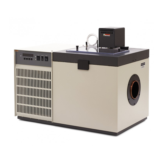
Digital remote communications is optionally available with a RS-232 or IEEE-488 interface. The tank for the 7008 is stainless steel. The 7008 holds 44 liters. There are two lids available the standard lid with a rectangular access hole and an optional lid... - Page 18 7008 Users Guide Figure 1. Bath Assembly...
-
Page 19: Specifications And Environmental Conditions
Chapter 3 Specifications and Environmental Conditions 3.1 Specifications Table 2. Specifications −5 °C to 110 °C Temperature range ±0.002 °C Temperature set ability ±0.002 °C Temperature reset ability ±1.0 °C Accuracy ±0.0007 °C at 25 °C (water) Stability 0.001 °C at 25 °C (mineral oil) Tank capacity 42 liters (11.2 gal) Access opening... -
Page 20: Environmental Conditions
7008 Users Guide 3.2 Environmental Conditions Although the instrument has been designed for optimum durability and trouble- free operation, it must be handled with care. The instrument should not be operated in an excessively dusty or dirty environment. Maintenance and cleaning recommendations can be found in the Maintenance Section of this manual. -
Page 21: Quick Start
Incorrect handling can damage the bath and void the warranty. This section gives a brief summary of the steps required to set up and operate the 7008 bath. This should be used as a general overview and reference and not as a substitute for the remainder of the manual. -
Page 22: Power
7008 Users Guide Fill the bath tank with an appropriate liquid. For operation at moderate bath temperatures, clean distilled water works well. Carefully pour the fluid into the bath tank through the large rectangular access hole above the tank avoiding spilling any fluid. - Page 23 Quick Start 4.4 Setting the Temperature Press SET to accept the new value and display the vernier value. The bath begins heating or cooling to the new set-point. Store new set-point, access vernier 0.00000 Current vernier value Press “EXIT” and the bath temperature will be displayed again. Return to the temperature display 24.73 C Bath temperature display...
- Page 24 7008 Users Guide...
-
Page 25: Installation
5.1 Bath Environment The Model 7008 Bath is a precision instrument which should be located in an appropriate environment. The location should be free of drafts, extreme temperatures and temperature changes, dirt, etc. The surface where the bath is placed must be level. -
Page 26: Dry-Out" Period
IEC 1010-1. 5.3 Bath Preparation and Filling The Model 7008 Bath is not provided with a fluid. Various fluids are available from Hart Scientific and other sources. Depending on the desired temperature range, any of the following fluids, as well as others, may be used in the bath: •... -
Page 27: Bath Use
Chapter 6 Bath Use READ BEFORE PLACING THE BATH IN SERVICE The information in this section is for general information only. It is not designed to be the basis for calibration laboratory procedures. Each laboratory will need to write their own specific procedures. 6.1 General Be sure to select the correct fluid for the temperature range of the calibration. -
Page 28: Comparison Calibration
7008 Users Guide 6.2 Comparison Calibration Comparison calibration involves testing a probe (unit under test, UUT) against a reference probe. After inserting the probes to be calibrated into the bath, allow sufficient time for the probes to settle and the temperature of the bath to stabilize. -
Page 29: Parts And Controls
Chapter 7 Parts and Controls 7.1 Front Control Panel The following controls and indicators are present on the controller front panel (see Figure 2 below): (1) the digital LED display, (2) the control buttons, (3) the bath on/off power switch, (4) the control indicator light, (5) the heater power switch, and (6) the cooling power switch. -
Page 30: Side Panel
7008 Users Guide Figure 2. Front Panel 5. The heater power switch is used to select the appropriate heater power levels for heating and controlling the bath at various temperatures. 6. The cooling power switch controls power to the cooling compressor and cooling fan. -
Page 31: Back Panel
Parts and Controls Back Panel 2. The COOLING TEMPERATURE regulating valve is used to adjust the temperature at which the refrigerant evaporates, which determines cooling efficiency. The ideal temperature for operation is about 5-10 degrees Celsius below the desired bath temperature. Refer to label below gauge for approximate psi and evaporative temperature settings. - Page 32 7008 Users Guide Always use a container of adequate size to hold the FULL LOAD of fluid. Some oils are more easily drained at higher temperatures. (See caution note in next section.) 6. The model and serial number Figure 4. Back Panel 7.
-
Page 33: Lid
Parts and Controls There are two different types of lids. They all have the same overall dimensions but the optional lid (see Figure 5) has a recirculation pump and the standard lid has a stirring motor with rectangular access hole. Their features are described with reference to figure numbers as follows: Figure 5. - Page 34 7008 Users Guide 1. This is the top half of the latch which attaches the lid to the bath. There are two latches one on the front and one on the back. 2. The thermometer/liquid level is a hole in the lid for filling and removing of liquid, checking liquid level and for mounting a thermometer.
-
Page 35: General Operation
Chapter 8 General Operation 8.1 Heat Transfer Fluid Many fluids will work with 7008 bath. Choosing a fluid requires consideration of many important characteristics of the fluid. Among these are temperature range, viscosity, specific heat, thermal conductivity, thermal expansion, electrical conductivity, fluid lifetime, safety, and cost. -
Page 36: Specific Heat
7008 Users Guide 8.1.3 Specific Heat Specific heat is the measure of the heat storage ability of the fluid. Specific heat, though to a lesser degree, also affects the control stability. It also affects the heating and cooling rates. Generally, a lower specific heat causes slightly better control stability and quicker heating and cooling. -
Page 37: Cost
General Operation 8.1 Heat Transfer Fluid WARNING: Fluids at high temperatures. May pose danger from BURNS, FIRE, and TOXIC fumes. Use appropriate caution and safety equipment. Fluids may be flammable and require special fire safety equipment and procedures. An important characteristic of the fluid to consider is the flash point. The flash point is the temperature at which there is sufficient vapor given off so that when there is sufficient oxygen present and an ignition source is applied the vapor will ignite. -
Page 38: Fluid Characteristics Chart
7008 Users Guide 8.1.10.3 Methanol Methanol or methyl alcohol is often used at low temperatures below 0 °C. Methanol is relatively inexpensive, has good control characteristics, and has a low freeze point. Methanol is very toxic so care must be taken when using and disposing of this fluid. - Page 39 General Operation 8.1 Heat Transfer Fluid 8.1.11.2 About the Graph The fluid graph visually illustrates some of the important qualities of the fluids shown. Temperature Range: The temperature scale is shown in degrees Celsius. A sense of the fluid’s general range of application is indicated. Qualities including pour point, freeze point, important viscosity points, flash point, boiling point and others may be shown.
- Page 40 7008 Users Guide Fume Point: The fume point is the point at which a fume hood should be used. This point is very subjective in nature and is impacted by individual tolerance to different fumes and smells, how well the bath is covered, the surface area of the fluid in the bath, the size and ventilation of the facility where the bath is located and others.
-
Page 41: Stirring
General Operation 8.1 Heat Transfer Fluid Stirring Stirring of the bath fluid is very important for stable temperature control. The fluid must be mixed well for good temperature uniformity and fast controller response. The stirrer is precisely adjusted for optimum performance. Power Power to the bath is provided by an AC mains supply of 115 VAC (10 %), 60 Hz, 14 A (230 VAC [ ±10 %], 50 Hz, 7 a optional). -
Page 42: Cooling
7008 Users Guide Cooling The BACK PRESSURE control valve limits the cooling capacity of the unit. It will normally be open all the way (full CCW) for temperature slewing and operation. If during operation the front panel meter indicates excessive cooling, this valve is closed partially (turn CW) until the percentage of heating to cooling is brought into line. -
Page 43: Controller Operation
Chapter 9 Controller Operation This section discusses in detail how to operate the bath temperature controller using the front control panel. Using the front panel key switches and LED display the user may monitor the bath temperature, set the temperature set-point in degrees C or F, monitor the heater output power, adjust the controller proportional band, set the cut-out set-point, and program the probe calibration parameters, operating parameters, serial and IEEE-488 interface configuration,... - Page 44 7008 Users Guide The cut-out has two modes — automatic reset and manual reset. The mode determines how the cut-out is reset which allows the bath to heat up again. When in automatic mode, the cut-out will reset itself as soon as the temperature is lowered below the cut-out set-point.
- Page 45 Controller Operation Reset Cut-out Figure 7. Controller Operation Flowchart...
-
Page 46: Temperature Set-Point
7008 Users Guide rESEt ? Cut-out reset function Press “SET” once more to reset the cut-out. Reset cut-out This will also switch the display to the set temperature function. To return to displaying the temperature press the “EXIT” button. If the cut-out is still in the over-temperature fault condition the display will continue to flash “cut-out”. -
Page 47: Set-Point Value
Controller Operation 9.3 Temperature Set-point 9.3.2 Set-point Value The set-point value may be adjusted after selecting the set-point memory and pressing “SET”. The set-point value is displayed with the units, C or F, at the left. Set-point 4 value in °C 40.00 If the set-point value need not be changed then press “EXIT”... -
Page 48: Temperature Scale Units
7008 Users Guide 9.4 Temperature Scale Units The temperature scale units of the controller may be set by the user to degrees Celsius ( °C) or Fahrenheit ( °F). The units will be used in displaying the bath temperature, set-point, vernier, proportional band, and cut-out set-point. -
Page 49: Secondary Menu
Controller Operation Secondary Menu Secondary Menu Functions which are used less often are accessed within the secondary menu. The secondary menu is accessed by pressing SET and EXIT simultaneously and then releasing. The first function in the secondary menu is the heater power display. - Page 50 7008 Users Guide If the proportional band is too narrow the bath temperature may swing back and forth because the controller overreacts to temperature variations. For best control stability the proportional band must be set for the optimum width. Figure 8. Bath temperature fluctuation at various proportional band settings...
- Page 51 Controller Operation Proportional Band Table 4. Proportional Band — Fluid Table Proportional Fluid Temperature Heater Setting Stability Band 30.0 °C 0.04 °C ±0.0004 °C Water 60.0 °C 0.04 °C ±0.001 °C Water 35.0 °C 0.05 °C ±0.0005 °C Eth-Gly 50% 60.0 °C 0.05 °C ±0.001 °C...
-
Page 52: Cut-Out
7008 Users Guide 9.8 Cut-out As a protection against software or hardware fault, shorted heater triac, or user error, the bath is equipped with an adjustable heater cut-out device that will shut off power to the heater if the bath temperature exceeds a set value. This protects... -
Page 53: Controller Configuration
Controller Operation 9.10 Probe Parameters Menu To accept the new cut-out set-point press “SET”. Accept cut-out set-point The next function is the configuration menu. Press “EXIT” to resume displaying the bath temperature. Controller Configuration The controller has a number of configuration and operating options and calibration parameters which are programmable via the front panel. -
Page 54: Cut-Out Reset Mode
7008 Users Guide Press “SET” to enter the menu. The operating parameters menu contains the cut-out reset mode setting. 9.11.1 Cut-out Reset Mode The cut-out reset mode determines whether the cut-out resets automatically when the bath temperature drops to a safe value or must be manually reset by the operator. -
Page 55: Sample Period
Controller Operation 9.12 Serial Interface Parameters The baud rate of the bath serial communications may be programmed to 300, 600, 1200, or 2400 baud. Use “UP” or “DOWN” to change the baud rate value. 2400 b New baud rate Press “SET” to set the baud rate to the new value or “EXIT” to abort the operation and skip to the next parameter in the menu. -
Page 56: Linefeed
7008 Users Guide 9.12.4 Linefeed The final parameter in the serial interface menu is the linefeed mode. This parameter enables (on) or disables (off) transmission of a linefeed character (LF, ASCII 10) after transmission of any carriage-return. The linefeed parameter is... -
Page 57: Calibration Parameters
Parameter CTO sets the calibration of the over-temperature cut-out. This is not adjustable by software but is adjusted with an internal potentiometer. For the 7008 bath this parameter should read between 110 and 130. 9.14.2 H and L These parameters set the upper and lower set-point limits of the bath. DO NOT change the values of these parameters from the factory set values. - Page 58 7008 Users Guide 9-16...
-
Page 59: Digital Communication Interface
Chapter 10 Digital Communication Interface If supplied with the option, the 7008 bath is capable of communicating with and being controlled by other equipment through the digital interface. Two types of digital interface are available — the RS-232 serial interface and the IEEE-488 GPIB interface. -
Page 60: Wiring
Press “SET” to choose to set the baud rate. The current baud rate value will then be displayed. The baud rate of the 7008 serial communications may be programmed to 300, 600, 1200, or 2400 baud. The baud rate is pre-programmed to 1200 baud. -
Page 61: Serial Operation
“SAmPLE”. The sample period is the time period in seconds between temperature measurements transmitted from the serial interface. If the sample rate is set to 5 for instance then the 7008 will transmit the current measurement over the serial interface approximately every five seconds. The automatic sampling is disabled with a sample period of 0. - Page 62 7008 Users Guide Table 5. Interface Command Summary 10-4...
- Page 63 Digital Communication Interface 10.2 IEEE-488 Communication (optional) Digital Communications Summary continued 10-5...
-
Page 64: Ieee-488 Interface Address
7008 Users Guide Digital Communications Summary continued To enter the IEEE-488 parameter programming menu first press “EXIT” while pressing “SET” and release to enter the secondary menu. Press “SET” repeatedly until the display reaches “PrObE”. This is the menu selection. Press “UP”... -
Page 65: Power Control Functions
1) switching the heater switch to LOW, and 2) switching the refrigeration switch to OFF. Otherwise, the interface would not be able to switch these functions off. The 7008 bath has four control functions with the digital interface. These are heater power high/low, cooling on/off, and expansion valve open/closed and back pressure valve open/closed. - Page 66 7008 Users Guide The “F4" command controls the back pressure valve. When the valve is closed the cooling capacity will be significantly reduced. This valve should normally be left open throughout the operating range of the bath. Table 6 summarizes the control functions for heating and cooling.
-
Page 67: Calibration Procedure
Chapter 11 Calibration Procedure In some instances the user may want to calibrate the bath to improve the temperature set-point accuracy. Calibration is done by adjusting the controller probe calibration constants D0 and DG so that the temperature of the bath as measured with a standard thermometer agrees more closely with the bath set- point. -
Page 68: Computing D And D
7008 Users Guide 11.3 Computing D and D Before computing the new values for D and D the current values must be known. The values may be found by either accessing the probe calibration menu from the controller panel or by inquiring through the digital interface. - Page 69 Calibration Procedure 11.2 Measuring the Set-point Error D0 = −25.229 DG = 0.0028530 = 75.00 C measured t =74.901 C Compute errors, = 24.869 − 25.00 °C = −0.131 °C = 74.901 − 75.00 °C = −0.099 °C Compute C −...
- Page 70 7008 Users Guide 11-4...
-
Page 71: Maintenance
Chapter 12 Maintenance The calibration instrument has been designed with the utmost care. Ease of operation and simplicity of maintenance have been a central theme in the product development. Therefore, with proper care the instrument should require very little maintenance. Avoid operating the instrument in dirty or dusty environments. - Page 72 7008 Users Guide • If a hazardous material is spilt on or inside the equipment, the user is responsible for taking the appropriate decontamination steps as outlined by the national safety council with respect to the material. MSDS sheets applicable to all fluids used in the baths should be kept in close proximity to the instrument.
-
Page 73: Troubleshooting
Chapter 13 Troubleshooting This section contains information on troubleshooting and CE Comments. This information pertains to a number of bath models and certain specifics may not pertain to your model. 13.1 Troubleshooting In the event that the instrument appears to function abnormally, this section may help to find and solve the problem. - Page 74 7008 Users Guide temperature’. • Normally, the cutout disconnects power to the heater when the bath temperature exceeds the cutout set-point causing the temperature to drop back down to a safe value. If the cutout mode is set to “AUTO”, the heater switches back on when the temperature drops.
-
Page 75: Troubleshooting
Troubleshooting 13.1 Troubleshooting 1.3) for assistance. The displayed process temperature is in Possible causes may be either a faulty error and the controller remains in the control probe or erroneous data in memory. cooling or the heating state at any set-point •... - Page 76 7008 Users Guide temperature’. • Check that the control probe has not been struck, bent, or damaged. If the cause of the problem remains un- known, contact an Authorized Service Center (see Section 1.3) for assistance. The controller shows that the out- put power...
- Page 77 Troubleshooting 13.1 Troubleshooting The bath does not achieve low temperatures Too much heating or not enough cooling can cause this problem. • Check that the control indicator glows green showing that the controller is attempting to cool. The heaters maybe disabled as a test by temporarily removing the heater fuses.
-
Page 78: Comments
7008 Users Guide 13.2 Comments 13.2.1 EMC Directive Hart Scientifics’ equipment has been tested to meet the European Electromagnetic Compatibility Directive (EMC Directive, 89/336/EEC). The Declaration of Conformity for your instrument lists the specific standards to which the unit was tested.
Need help?
Do you have a question about the 7008 and is the answer not in the manual?
Questions and answers