Table of Contents
Advertisement
Quick Links
Via Acquanera, 29
22100 Como
tel. 031.526.566 (r.a.) fax 031.507.984
info@calpower.it
www.calpower.it
August 2012
© 2012 Fluke Corporation. All rights reserved. Specifications are subject to change without notice.
All product names are trademarks of their respective companies.
7341
Calibration Bath
Users Guide
Advertisement
Table of Contents
Troubleshooting

Subscribe to Our Youtube Channel
Related Manuals for Fluke 7341


Summary of Contents for Fluke 7341
- Page 1 Via Acquanera, 29 22100 Como tel. 031.526.566 (r.a.) fax 031.507.984 info@calpower.it www.calpower.it 7341 Calibration Bath Users Guide August 2012 © 2012 Fluke Corporation. All rights reserved. Specifications are subject to change without notice. All product names are trademarks of their respective companies.
- Page 2 Fluke authorized resellers shall extend this warranty on new and unused products to end-user customers only but have no authority to extend a greater or different warranty on behalf of Fluke. Warranty support is available only if product is purchased through a Fluke authorized sales outlet or Buyer has paid the applicable international price.
-
Page 3: Table Of Contents
Table of Contents Chapter Title Page Before You Start .................. 1-1 Symbols Used ....................1-3 Safety Information ..................... 1-4 Authorized Service Centers ................1-7 Introduction ..................2-1 Specifications and Environmental Conditions ......... 3-1 Specifications ..................... 3-3 Environmental Conditions ................. 3-4 Quick Start ................... - Page 4 7341 Users Guide Parts and Controls ................7-1 Front Control Panel .................... 7-3 Back Panel ......................7-3 Fluid Expansion Reservoir ................. 7-3 General Operation ................8-1 Heat Transfer Fluid .................... 8-3 Temperature Range ..................8-3 Viscosity ......................8-3 Specific Heat ....................8-3 Thermal Conductivity ..................
- Page 5 Contents (continued) ALPHA ......................9-13 Operating Parameters ..................9-13 Cutout Reset Mode ..................9-13 Cooling Mode ....................9-14 Hot Gas Bypass Mode ................... 9-14 Serial Interface Parameters ................9-15 Baud Rate ...................... 9-15 Sample Period ....................9-15 Duplex Mode ....................9-15 Linefeed ......................
- Page 6 7341 Users Guide...
- Page 7 List of Tables Table Title Page 1-1. International Electrical Symbols ................1-3 3-1. Specifications ......................3-3 8-1. Various Bath Fluids and Their Properties .............. 8-7 9-1. Program Mode Setting Actions ................9-9 9-2. Typical Proportional Band Settings for Various Fluids ......... 9-11 10-1.
- Page 8 7341 Users Guide...
- Page 9 List of Figures Figure Title Page 4-1. Stir Baffle Fill Levels ..................... 4-4 5-1. Tipping Prevention Bracket Installation ..............5-4 7-1. Front Control Panel ....................7-3 8-1. Chart of Various Bath Fluids and Their Properties ..........8-9 9-1. Controller Operation Flowchart ................9-4 9-2.
- Page 10 7341 Users Guide viii...
-
Page 11: Before You Start
Chapter 1 Before You Start Title Page Symbols Used ...................... 1-3 Safety Information ....................1-4 Authorized Service Centers ................. 1-7... - Page 12 7341 Users Guide...
-
Page 13: Symbols Used
Before You Start Symbols Used Symbols Used Table 1 lists the International Electrical Symbols. Some or all of these symbols may be used on the instrument or in this manual. Table 1-1. International Electrical Symbols Symbol Description AC (Alternating Current) ... -
Page 14: Safety Information
7341 Users Guide Safety Information Use this instrument only as specified in this manual. Otherwise, the protection provided by the instrument may be impaired. Refer to the safety information in Warnings and Cautions sections. The following definitions apply to the terms “Warning” and “Caution”. - Page 15 Before You Start Safety Information • The instrument is intended for indoor use only. • The bath is a precision instrument. Although it has been designed for optimum durability and trouble free operation, it must be handled with care. Position the bath before the tank is filled with fluid by rolling it into place.
- Page 16 7341 Users Guide BATH FLUIDS: • Fluids used in this bath may produce noxious or toxic fumes under certain circumstances. Consult the fluid manufacturer’s MSDS (Material Safety Data Sheet). Proper ventilation and safety precautions must be observed. • The instrument is equipped with a soft cutout (user settable firmware) and a hard cutout (set at the factory).
-
Page 17: Authorized Service Centers
Turning the instrument on and off frequently adds wear and tear to the compressor. Authorized Service Centers Please contact one of the following authorized Service Centers to coordinate service on your Fluke product: Fluke Corporation 799 E. Utah Valley Drive American Fork, UT 84003-9775 Phone: +1.801.763.1600... - Page 18 22 Jianguomenwai Dajie Chao Yang District Beijing 100004, PRC CHINA Phone: +86-10-6-512-3436 Telefax: +86-10-6-512-3437 E-mail: xingye.han@fluke.com.cn Fluke South East Asia Pte Ltd. Fluke ASEAN Regional Office Service Center 60 Alexandra Terrace #03-16 The Comtech (Lobby D) 118502 SINGAPORE Phone: +65 6799-5588 Telefax: +65 6799-5588 E-mail: antng@singa.fluke.com...
-
Page 19: Introduction
RS-232 and optional with an IEEE-488 interface. The 7341 bath was designed to be compact and low cost without compromising performance. The 7341 bath operates over a wide temperature range from -40°C to 150°C. The refrigeration permits sub-ambient temperature control. - Page 20 7341 Users Guide...
-
Page 21: Specifications And Environmental Conditions
Chapter 3 Specifications and Environmental Conditions Title Page Specifications ....................... 3-3 Environmental Conditions ................... 3-4... - Page 22 7341 Users Guide...
-
Page 23: Specifications
Specifications and Environmental Conditions Specifications Specifications Table 3-1describes the product specifications. Table 3-1. Specifications Item Description Range –45°C to 150°C ±0.005°C at –40°C (ethanol) Stability (2 sigma) ±0.005°C at 25°C (water) ±0.007°C at 150°C (5012 oil) ±0.007°C at –40°C (ethanol) Uniformity ±0.007°C at 25°C (water) ±0.010°C at 150°C (5012 oil) -
Page 24: Environmental Conditions
7341 Users Guide Environmental Conditions Although the instrument has been designed for optimum durability and trouble-free operation, it must be handled with care. The instrument should not be operated in an excessively dusty or dirty environment. Maintenance and cleaning recommendations can be found in the Maintenance Section of this manual. -
Page 25: Quick Start
Chapter 4 Quick Start Title Page Unpacking ......................4-3 Set Up ........................4-3 Power ........................4-5 Setting the Temperature ..................4-5... - Page 26 7341 Users Guide...
-
Page 27: Unpacking
Unpack the bath carefully and inspect it for any damage that may have occurred during shipment. If there is shipping damage, notify the carrier immediately. Verify that all components are present: • 7341 Bath • Access Hole Cover • Fluid Expansion Reservoir with Cover •... - Page 28 7341 Users Guide moderate bath temperatures, clean distilled water works well. Carefully pour the fluid into the bath tank through the large rectangular access hole above the tank avoiding spilling any fluid. Caution When filling the tank, ensure the immersion coils are completely covered.
-
Page 29: Power
Quick Start Power An overflow drain is provided for excess bath fluid due to expansion. This drains the fluid into the fluid expansion reservoir for reuse. See Fluid Expansion Reservoir in Chapter 7, for details in using the reservoir. Note As the temperature of the bath increases the fluid level will increase, see Chapter 6. - Page 30 7341 Users Guide Store new set-point, access vernier Current vernier value 0.00000 Press “EXIT” and the bath temperature will be displayed again. Return to the temperature display Bath temperature display 4.73C The bath heats or cools until it reaches the new set-point temperature. Turn off the cooling to reach and control at higher temperatures.
-
Page 31: Installation
Chapter 5 Installation Title Page Moving or Uncrating the Bath ................5-3 Bath Environment ....................5-3 Tipping Prevention Bracket Installation .............. 5-3 Installation On A Wood Floor ................5-3... - Page 32 7341 Users Guide...
-
Page 33: Moving Or Uncrating The Bath
Bath Environment The Model 7341 Bath is a precision instrument, which should be located in an appropriate environment. The location should be free of drafts, extreme temperatures and temperature changes, dirt, etc. The surface where the bath is placed must be level. -
Page 34: Installation On A Concrete Floor
Proceed to fill the bath with the applicable bath fluid after reading the entire Users Guide. If you have any questions concerning installation of the tipping prevention bracket, please contact a Fluke Authorized Service Center. “ Dry-out” Period If this equipment is used in a manner not specified by the manufacturer, the protection provided by the equipment may be impaired. -
Page 35: Bath Preparation And Filling
Cover the panel if necessary during filling. DO NOT overfill. The Model 7341 Bath is not provided with a fluid. Various fluids are available from Hart and other sources. Depending on the desired temperature range, any of the following fluids, as well as others, may be used in the bath: •... - Page 36 7341 Users Guide...
-
Page 37: Bath Use
Chapter 6 Bath Use Title Page General ......................... 6-3 Comparison Calibration ..................6-3 Calibration of Multiple Probes ................6-4... - Page 38 7341 Users Guide...
-
Page 39: General
Bath Use General Caution Read this chapter entitled BATH USE before placing the bath in service. The information in this section is for general information only. It is not designed to be the basis for calibration laboratory procedures. Each laboratory needs to write their specific procedures. -
Page 40: Calibration Of Multiple Probes
7341 Users Guide access cover. Other fixtures to hold the probes can be designed. The object is to keep the reference probe and the probe(s) to be calibrated as closely grouped as possible in the working area of the bath. Bath stability is maximized when the bath working area is kept covered. -
Page 41: Parts And Controls
Chapter 7 Parts and Controls Title Page Front Control Panel ....................7-3 Back Panel ......................7-3 Fluid Expansion Reservoir ................... 7-3... - Page 42 7341 Users Guide...
-
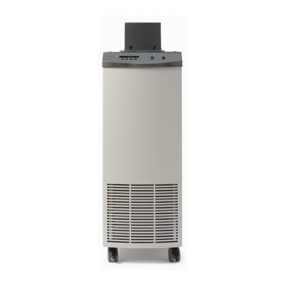
Page 43: Front Control Panel
Parts and Controls Front Control Panel Front Control Panel The following controls and indicators are present on the controller front panel (see Figure 7-1): (1) the digital LED display, (2) the control buttons, (3) the bath on/off power switch, (4) the control indicator light, and (5) the cooling on/off switch. haz003.eps Figure 7-1. - Page 44 7341 Users Guide receive excess fluid expanded in the process of heating the bath to higher temperatures. Any liquid will expand when heated. To prevent the bath from overflowing when the fluid expands, the excess fluid must be removed either prior to heating or by allowing it to drain out of the bath tank.
-
Page 45: General Operation
Chapter 8 General Operation Title Page Heat Transfer Fluid ....................8-3 Temperature Range ..................8-3 Viscosity ......................8-3 Specific Heat ....................8-3 Thermal Conductivity ..................8-3 Thermal Expansion ..................8-3 Electrical Resistivity ..................8-4 Fluid Lifetime ....................8-4 Safety ....................... 8-4 Cost ........................ - Page 46 7341 Users Guide...
-
Page 47: Heat Transfer Fluid
Heat Transfer Fluid Heat Transfer Fluid Many fluids will work with 7341 bath. Choosing a fluid requires consideration of many important characteristics of the fluid. Among these are temperature range, viscosity, specific heat, thermal conductivity, thermal expansion, electrical resistivity, fluid lifetime, safety, and cost. -
Page 48: Electrical Resistivity
7341 Users Guide fluid volume as the bath temperature increases may cause overflow. It may be dangerous to permit the fluid to overflow the tank. It may also cause loss of valuable bath fluid. Excessive thermal expansion may also be undesirable in applications where constant liquid level is important. -
Page 49: Cost
General Operation Heat Transfer Fluid adequate ventilation system must be used if hazardous or bothersome vapors are produced. Warning Fluids at high temperatures may pose danger from BURNS, FIRE, and TOXIC FUMES. Use appropriate caution and safety equipment. Fluids may be flammable and require special fire safety equipment and procedures. An important characteristic of the fluid to consider is the flash point. -
Page 50: Silicone Oil
Specifications may change and sources sometimes offer differing information. Fluke cannot be liable for any personal injury or damage to equipment, product or facilities resulting from the use of these fluids. The user of the bath is responsible for collecting correct information, exercising proper judgment, and insuring safe operation. - Page 51 General Operation Heat Transfer Fluid Table 8-1. Various Bath Fluids and Their Properties Fluid Lower Upper Viscosity Specific Thermal Thermal Resistivity Flash Specific (# = Temp. Temp. (centisto Heat Conductivity Expansion (1012Ω- Point Gravity Limit* Limit* kes) (cal/g/°C) (cal/s/cm/°C) (cm/cm/°C) Halocarb 70°C (e) NONE...
-
Page 52: About The Chart
7341 Users Guide About the Chart The fluid chart visually illustrates some of the important qualities of the fluids shown. Temperature Range: The temperature scale is shown in degrees Celsius. The shaded bands indicate the fluids’ general range of application. Qualities including pour point, freeze point, important viscosity points, flash point, boiling point and others may be shown. - Page 53 In the graph, it is assumed that the bath access hole is covered at this point. This is subject to user's company policy. Fluke recommends the use of a ventilation system as soon as the fluid produces vapors. Keep the access hole covered to reduce evaporation.
-
Page 54: Stirring
Temperature Controller Fluke’s unique hybrid digital/analog temperature controller controls the bath temperature. The controller offers the tight control stability of an analog temperature controller as well as the flexibility and programmability of a digital controller. -
Page 55: Refrigeration
General Operation Refrigeration LED display. Remote digital operation with the controller is possible via the standard RS- 232 serial port. The controller may be optionally equipped with an IEEE-488 GPIB digital interface. Operation of the controller using the front control panel is discussed following in Chapter 9, Controller Operation. - Page 56 7341 Users Guide small benefit to stability may be realized by using the hot gas bypass. • The refrigeration may be beneficially used for short times (less than one hour) above 60°C but less than 100°C. This list is not intended to be complete, but only suggests some of the situations when automatic modes may not be best.
-
Page 57: Controller Operation
Chapter 9 Controller Operation Title Page Bath Temperature ....................9-3 Reset Cutout ......................9-3 Temperature Set-point ..................9-5 Programmable Set-points ................9-5 Set-point Value ....................9-5 Set-point Vernier ..................... 9-6 Scan ........................9-6 Scan Control ....................9-6 Scan Rate ......................9-6 Temperature Scale Units .................. - Page 58 7341 Users Guide CTO ......................... 9-17 CO and CG ...................... 9-17 H and L ......................9-17 HGbt ........................ 9-17...
-
Page 59: Bath Temperature
Controller Operation Bath Temperature This chapter discusses in detail how to operate the bath temperature controller using the front control panel. Using the front panel key switches and LED display the user may monitor the bath temperature, set the temperature set-point in degrees C or F, monitor the heater output power, adjust the controller proportional band, set the cutout set-point, and program the probe calibration parameters, operating parameters, serial and IEEE-488 interface configuration, and controller calibration parameters. - Page 60 7341 Users Guide haz005.eps Figure 9-1. Controller Operation Flowchart Cutout reset function rEsEt? Press “SET” once more to reset the cutout. Reset cutout...
-
Page 61: Temperature Set-Point
Controller Operation Temperature Set-point This action switches the display to the set temperature function. To return to displaying the temperature display press the “EXIT” button. If the cutout is still in the over- temperature fault condition, the display continues to flash “cutout”. The bath temperature must drop a few degrees below the cutout set-point before the cutout can be reset. -
Page 62: Set-Point Vernier
7341 Users Guide access the set-point vernier. If “EXIT” is pressed, any changes made to the set-point are ignored. Accept new set-point value Set-point Vernier The user may want to adjust the set-point slightly to achieve a more precise bath temperature. -
Page 63: Temperature Scale Units
Controller Operation Temperature Scale Units cooling. The scan rate function appears in the main menu after the scan control function. The scan rate units are in degrees per minute, degrees C or F depending on the selected units. Scan rate in °C/min Sr=0.010 Press “UP”... -
Page 64: Set-Points
7341 Users Guide Number of program set-points Pn=8 Use the “UP” or “DOWN” buttons to change the number from 2 to 8. New number of program set-points Pn=3 Press “SET” to continue. Press “EXIT” to ignore any changes and to continue. -
Page 65: Program Control
Controller Operation Secondary Menu Table 9-1. Program Mode Setting Actions Function Action up-stop up-down-stop up-repeat up-down-repeat Program mode Pf=1 Use the “UP” or “DOWN” buttons to change the mode. New mode Pf=4 Press “SET” to continue. Enter program menu Program Control The final parameter in the program menu is the control parameter. -
Page 66: Proportional Band
7341 Users Guide Access heater power in secondary menu Heater power in percent 12 Pct To exit out of the secondary menu press “EXIT”. To continue on to the proportional band setting function press “SET”. Return to temperature display Proportional Band In a proportional controller such as this, the heater output power is proportional to the bath temperature over a limited range of temperatures around the set-point. - Page 67 Controller Operation Proportional Band because of the increased response time. The proportional band width is easily adjusted from the bath front panel. The width may be set to discrete values in degrees C or F depending on the selected units. The optimum proportional band width setting may be determined by monitoring the stability with a high resolution thermometer or with the controller percent output power display.
-
Page 68: Cutout
7341 Users Guide Cutout As a protection against software or hardware fault, shorted heater triac, or user error, the bath is equipped with an adjustable heater cutout device that shuts off power to the heater if the bath temperature exceeds a set value. This protects the heater and bath materials... -
Page 69: Controller Configuration
Controller Operation Controller Configuration Controller Configuration The controller has a number of configuration and operating options and calibration parameters, which are programmable via the front panel. These are accessed from the secondary menu after the cutout set-point function by pressing “SET.” There are 5 sets of configuration parameters - probe parameters, operating parameters, serial interface parameters, IEEE-488 interface parameters, and controller calibration parameters. -
Page 70: Cooling Mode
7341 Users Guide To change to manual reset mode press “UP” and then “SET”. Cutout set for manual reset Cto=rst Cooling Mode The cooling mode determines whether refrigeration is in Auto mode, On, or Off. Normally the cooling mode is set to Auto mode. In the Auto mode, the refrigeration is ‘On’... -
Page 71: Serial Interface Parameters
Controller Operation Serial Interface Parameters HGb mode set to on HGb mode set to off Serial Interface Parameters The serial interface menu is accessed by pressing “UP” from the operating parameters menu. The serial RS-232 interface parameters menu is indicated by, Serial RS-232 interface parameters menu SErIAL The serial interface parameters menu contains parameters which determine the operation... -
Page 72: Duplex Mode
7341 Users Guide Duplex Mode The next parameter is the duplex mode. The duplex mode may be set to full duplex or half duplex. With full duplex, any commands received by the bath via the serial interface are executed and immediately echoed or transmitted back to the device of origin. With half duplex, the commands are executed but not echoed. -
Page 73: Transmission Termination
Controller Operation Calibration Parameters Transmission Termination The transmission termination character can be set to carriage return only, linefeed only, or carriage return and linefeed. Regardless of the option selected, the instrument will interpret either a carriage return or a linefeed as a command termination during reception. The termination parameter is indicated with, IEEE-488 termination Press “SET”... - Page 74 7341 Users Guide This parameter is the temperature where the hot gas bypass activates. This parameter is factory set. To insure the bath's best performance without damaging its compressor, DO NOT alter the value of this parameter. 9-18...
-
Page 75: Digital Communication Interface
Chapter 10 Digital Communication Interface Title Page Serial Communications ..................10-3 Wiring ......................10-3 Setup ........................ 10-4 Baud Rate ....................10-4 Sample Period ..................... 10-4 Duplex Mode ....................10-4 Linefeed ...................... 10-4 Serial Operation ....................10-4 IEEE-488 Communication (optional) ..............10-4 Setup ........................ - Page 76 7341 Users Guide 10-2...
-
Page 77: Serial Communications
Digital Communication Interface Serial Communications The 7341 bath is capable of communicating with and being controlled by other equipment through the digital interface. Two types of digital interface are available - the RS-232 serial interface which is standard and the IEEE-488 GPIB interface which is optional. -
Page 78: Setup
7341 Users Guide Setup Before operation the serial interface of the bath must first be set up by programming the baud rate and other configuration parameters. These parameters are programmed within the serial interface menu. To enter the serial parameter programming menu, press “EXIT” while holding down “SET”, then release both buttons to enter the secondary menu. -
Page 79: Setup
A terminating CR is implied with all commands. Cooling Control The 7341 bath has a fully automated refrigeration control system when the cooling power switch on the front panel is activated. Under normal conditions, the refrigeration is on at any temperature below approximately 60°C (see Refrigeration in Chapter 8). - Page 80 7341 Users Guide in the following ways. • The cooling (refrigeration) may be set to operate in the auto, on, or off modes. See Cooling Mode in Chapter 9. • The hot gas bypass or reduced cooling mode may also be set to on, off, or auto.
- Page 81 Digital Communication Interface Cooling Control Table 10-1. Interface Command Summary (cont.) Command Command Returned Command Acceptable Returned Description Values Format Example Example Ramp and Soak Menu Read number of pn: 9 pn: 2 programmable set-points Set number of pn=n pn=4 programmable set-points to n Read programmable set-...
- Page 82 7341 Users Guide Table 10-1. Interface Command Summary (cont.) Command Command Returned Command Acceptable Returned Description Values Format Example Example Configuration Menu Probe Menu Read R0 calibration r[0] r0: 999.999 r0: 100.578 parameter Set R0 calibration r[0]=n r=100.324 98.0 to parameter to n 104.999...
- Page 83 Set high set-point limit to n Miscellaneous (not on menus) list of extended Read all extended parameters parameters *ver[sion] *ver ver.9999,9.99 ver.7341,1. Read firmware version number *all *all list of operating Read all operating parameters parameters h[elp] list of commands...
- Page 84 7341 Users Guide 10-10...
-
Page 85: Calibration Procedure
Chapter 11 Calibration Procedure Title Page Calibration Points ....................11-3 Measuring the Set-point Error ................11-3 Computing R0 and ALPHA ................. 11-3 Calibration Example .................... 11-4 11-1... - Page 86 7341 Users Guide 11-2...
-
Page 87: Calibration Points
Calibration Procedure Calibration Points In some instances the user may want to calibrate the bath to improve the temperature set- point accuracy. Calibration is done by adjusting the controller probe calibration constants R0 and ALPHA so that the temperature of the bath as measured with a standard thermometer agrees more closely with the bath set-point. -
Page 88: Calibration Example
7341 Users Guide and measuring the errors again. If desired, the calibration procedure may be repeated again to further improve the accuracy. Calibration Example The bath is to be used between 25°C and 75°C and it is desired to calibrate the bath as accurately as possible for operation within this range. -
Page 89: Maintenance
Chapter 12 Maintenance The calibration instrument has been designed with the utmost care. Ease of operation and simplicity of maintenance have been a central theme in the product development. Therefore, with proper care the instrument should require very little maintenance. Avoid operating the instrument in dirty or dusty environments. - Page 90 • Before using any cleaning or decontamination method except those recommended by Fluke, users should check with an Authorized Service Center (see Authorized Service Centers in Chapter 1) to be sure that the proposed method will not damage the equipment.
-
Page 91: Troubleshooting
Chapter 13 Troubleshooting Title Page Troubleshooting ....................13-3 Comments ......................13-6 EMC Directive ....................13-6 Immunity Testing ..................13-6 Emission Testing ..................13-6 Low Voltage Directive (Safety) ..............13-6 13-1... - Page 92 7341 Users Guide 13-2...
-
Page 93: Troubleshooting
Troubleshooting Troubleshooting This section contains information on troubleshooting, CE Comments, and a wiring diagram. This information pertains to a number of bath models and certain specifics may not pertain to your model. Troubleshooting In the event that the instrument appears to function abnormally, this section may help to find and solve the problem. - Page 94 7341 Users Guide • If the problem reoccurs, the battery should be replaced. Contact an Authorized Service Center (see Authorized Service Centers in Chapter 1) for assistance. • If initializing the memory does not remedy the problem, there may be a failed electronic component. Contact an Authorized Service Center (see Authorized Service Centers in Chapter 1) for assistance.
- Page 95 Troubleshooting Service Center (see Authorized Service Centers in Chapter 1) for assistance. The controller does not Note: Before performing the memory check, you need to record the maintain controller parameters controller calibration parameters (found in the CAL menu of the or parameters are reset each instrument) and any user-adjusted parameters that you have changed time the power to the unit is...
-
Page 96: Comments
Class B equipment. The instrument was not designed to be used in domestic establishments. Low Voltage Directive (Safety) In order to comply with the European Low Voltage Directive (73/23/EEC), Fluke equipment has been designed to meet the following standards: •...
Need help?
Do you have a question about the 7341 and is the answer not in the manual?
Questions and answers