Table of Contents
Advertisement
7102
Micro-Bath
User's Guide
PN 3729328
December 2013
© 2013 Fluke Corporation. All rights reserved. Specifications are subject to change without notice.
All product names are trademarks of their respective companies.
GlobalTestSupply
www.
.com
Find Quality Products Online at:
sales@GlobalTestSupply.com
Advertisement
Table of Contents

Related Manuals for Fluke 7102


Summary of Contents for Fluke 7102
- Page 1 7102 Micro-Bath User's Guide PN 3729328 December 2013 © 2013 Fluke Corporation. All rights reserved. Specifications are subject to change without notice. All product names are trademarks of their respective companies. GlobalTestSupply www. .com Find Quality Products Online at: sales@GlobalTestSupply.com...
- Page 2 Fluke authorized resellers shall extend this warranty on new and unused products to end-user customers only but have no authority to extend a greater or different warranty on behalf of Fluke. Warranty support is available only if product is purchased through a Fluke authorized sales outlet or Buyer has paid the applicable international price.
-
Page 3: Table Of Contents
Table of Contents Chapter Title Page Before You Start .................. 1-1 1.1 Symbols Used ................. 1-1 1.2 Safety Information ................1-2 1.2.1 Warnings ................1-2 1.2.2 Cautions ................... 1-4 1.3 Authorized Service Centers ............. 1-5 Introduction ..................2-1 Specifications and Environmental Conditions ......... 3-1 3.1 Specifications .................. - Page 4 7102 User's Guide Parts and Controls ................7-1 7.1 Front Panel ..................7-1 7.2 Back Panel ..................7-2 7.3 Accessories ..................7-3 7.3.1 Transport/Pour Access Lid ............7-3 7.3.2 Access Cover (Optional) ............7-4 7.3.3 Probe Basket ................7-4 7.3.4 Stir Bar ..................7-4 7.3.5 Well Extender (Optional) ............
- Page 5 Contents (continued) 9.8.1 Operating Parameters .............. 9-8 9.8.1.1 High Limit ................9-9 9.8.1.2 Stir Speed ................9-9 9.8.2 Serial Interface Parameters ............9-9 9.8.2.1 Baud Rate ................9-10 9.8.2.2 Sample Period ..............9-10 9.8.2.3 Duplex Mode ..............9-10 9.8.2.4 Linefeed ................9-11 9.8.3 Calibration Parameters .............
- Page 6 7102 User's Guide GlobalTestSupply www. .com Find Quality Products Online at: sales@GlobalTestSupply.com...
- Page 7 List of Tables Table Title Page International Electrical Symbols ..............1-1 Specifications .................... 3-1 Table of Various Bath Fluids ..............8-5 Nominal Stirrer Motor SettingsWith Different Liquids ........ 8-8 Controller Communications Commands ............ 10-4 GlobalTestSupply www. .com Find Quality Products Online at: sales@GlobalTestSupply.com...
- Page 8 7102 User's Guide GlobalTestSupply www. .com Find Quality Products Online at: sales@GlobalTestSupply.com...
- Page 9 List of Figures Figure Title Page 7102 Front Panel ..................7-1 7102 Back Panel and Bottom ..............7-2 Bath Lids and Lid Parts ................7-3 Probe Basket ..................... 7-4 Stir Bar ...................... 7-4 Chart of Various Bath Fluids ..............8-6 Controller Operation Flowchart ..............
- Page 10 7102 User's Guide viii GlobalTestSupply www. .com Find Quality Products Online at: sales@GlobalTestSupply.com...
-
Page 11: Before You Start
Chapter 1 Before You Start 1.1 Symbols Used Table 1 lists the International Electrical Symbols. Some or all of these symbols may be used on the instrument or in this manual. Table 1. International Electrical Symbols Symbol Description AC (Alternating Current) ... -
Page 12: Safety Information
7102 User's Guide 1.2 Safety Information Use this instrument only as specified in this manual. Otherwise, the protection provided by the instrument maybe impaired. The following definitions apply to the terms “Warning” and “Caution”. • “Warning” identifies conditions and actions that may pose hazards to the user. - Page 13 Before You Start 1.2 Safety Information • Before initial use, or after transport, or after storage in humid or semi-humid environments, or anytime the instrument has not been energized for more than 10 days, the instrument needs to be energized for a “dry-out” period of 2 hours before it can be assumed to meet all of the safety requirements of the IEC 61010-1.
-
Page 14: Cautions
7102 User's Guide ELECTRICAL HAZARD • These guidelines must be followed to ensure that the safety mechanisms in this instrument will operate properly. This instrument must be plugged into an AC only electric outlet as listed in Section 3.1, Specifications. The power cord of the instrument is equipped with a three-pronged grounding plug for your protection against electrical shock hazards. -
Page 15: Authorized Service Centers
Before You Start 1.3 Authorized Service Centers • DO NOT operate this instrument in an excessively wet, oily, dusty, or dirty environment. • The unit is a precision instrument. Although it has been designed for optimum durability and trouble free operation, it must be handled with care. - Page 16 7102 User's Guide • Model Number • Serial Number • Voltage • Complete description of the problem GlobalTestSupply www. .com Find Quality Products Online at: sales@GlobalTestSupply.com...
-
Page 17: Introduction
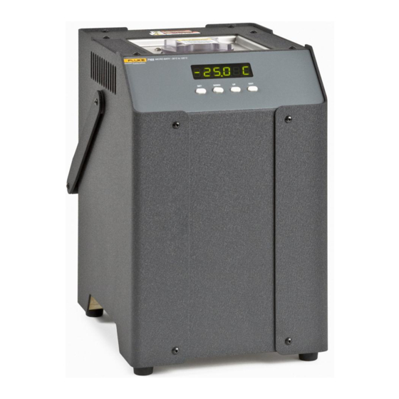
The Hart Scientific 7102 Micro-Bath may be used as a portable instrument or bench top temperature calibrator for calibrating thermocouple and RTD temperature probes. The 7102 is small enough to use in the field, and accurate enough to use in the lab. With an ambient temperature of 23 °C (74 °F), calibrations may be done over a range of −5 °C to 126 °C (23 °F to 259 °F). - Page 18 7102 User's Guide GlobalTestSupply www. .com Find Quality Products Online at: sales@GlobalTestSupply.com...
-
Page 19: Specifications And Environmental Conditions
Chapter 3 Specifications and Environmental Conditions 3.1 Specifications Table 2. Specifications −5 to 125 °C (23 to 257 °F) Range ±0.25 °C Accuracy ±0.015 °C at −5 °C (oil, 5010) Stability ±0.03 °C at 121 °C (oil, 5010) ±0.02 °C Uniformity 0.01 °C/F Resolution... -
Page 20: Environmental Conditions
7102 User's Guide 3.2 Environmental Conditions Although the instrument has been designed for optimum durability and trouble- free operation, it must be handled with care. The instrument should not be operated in an excessively dusty or dirty environment. Maintenance and cleaning recommendations can be found in the Maintenance Section of this manual. -
Page 21: Quick Start
Unpack the Micro-Bath carefully and inspect it for any damage that may have occurred during shipment. If there is shipping damage, notify the carrier immediately. Verify that the following components are present: • 7102 Micro-Bath • Transport/Pour Access Lid • Probe Basket •... -
Page 22: Setup
7102 User's Guide 4.2 Setup Caution: DO NOT operate this instrument without fluid. Place the calibrator on a flat surface with at least 6 inches of free space around the instrument. Plug the power cord into a grounded mains outlet. Observe that the nominal voltage corresponds to that indicated on the back of the calibrator. -
Page 23: Installation
5.1 Bath Environment The 7102 Micro Bath is a precision instrument which should be located in an appropriate environment. The location should be free of drafts, extreme temperatures and temperature changes, dirt, etc. The surface where the bath is placed must be level. -
Page 24: Bath Preparation And Filling
User's Guide 5.3 Bath Preparation and Filling The 7102 Micro Bath is not provided with a fluid. Various fluids are available from Hart Scientific and other sources. Depending on the desired temperature range, any of the following fluids, as well as others, may be used in the bath: •... -
Page 25: Bath Use
Chapter 6 Bath Use Caution: Read before placing the bath in service The information in this section is for general information only. It is not designed to be the basis for calibration laboratory procedures. Each laboratory will need to write their own specific procedures. -
Page 26: Comparison Calibration
7102 User's Guide Warning: Some of the high temperature fluids react violently to water or other liquid mediums. For optimum accuracy and stability, allow the bath adequate stabilization time after reaching the set-point temperature. 6.2 Comparison Calibration Comparison calibration involves testing a probe (unit under test, UUT) against a reference probe. -
Page 27: Parts And Controls
The user should become familiar with the bath and its parts: 7.1 Front Panel Figure 1 on this page. Figure 1. 7102 Front Panel Controller Display – The digital display is an important part of the temperature controller because it not only displays set and actual temperatures but also displays various calibrator functions, settings, and constants. -
Page 28: Back Panel
7.2 Back Panel Figure 2 on next page. Power Cord – Underneath the calibrator is the removable power cord inlet that plugs into an IEC grounded socket. Figure 2. 7102 Back Panel and Bottom GlobalTestSupply www. .com Find Quality Products Online at:... -
Page 29: Accessories
Parts and Controls 7.3 Accessories Power Switch – The power switch is located on the power entry module (PEM). The PEM also houses the fuses and the dual voltage selector. The PEM allows the unit to be field switchable for 115 VAC ( ±10 %) or 230 VAC ( ±10 %) operation. -
Page 30: Access Cover (Optional)
7102 User's Guide 7.3.2 Access Cover (Optional) An aluminum access cover (Figure 3) is available for optimum stability. Holes should be drilled in the access cover to allow insertion of the probes into the well. The holes must be within the guide ring for the probes to fit into the probe basket. -
Page 31: General Operation
Press “SET” to store changes. 8.2 Switching to 230V Operation The 7102 is switchable from 115 VAC to 230 VAC 50/60 Hz. Switching the voltage can change the calibration, so the unit should be calibrated after changing the input voltage. -
Page 32: Bath Fluid
7102 User's Guide 8.3 Bath Fluid Many fluids work with the 7102 bath. Choosing a fluid requires consideration of many important characteristics of the fluid. Among these are temperature range, viscosity, specific heat, thermal conductivity, thermal expansion, electrical resistivity, fluid lifetime, safety, and cost. -
Page 33: Thermal Expansion
General Operation Bath Fluid 8.3.5 Thermal Expansion Thermal expansion describes how the volume of the fluid changes with temperature. Thermal expansion of the fluid used must be considered since the increase in fluid volume as the bath temperature changes may cause overflow. Excessive thermal expansion may also be undesirable in applications where constant liquid level is important. -
Page 34: Commonly Used Fluids
7102 User's Guide 8.3.10 Commonly Used Fluids Below is a description of some of the more commonly used fluids and their characteristics. 8.3.10.1 Water (Distilled) Water is often used because of its very low cost, availability, and excellent temperature control characteristics. Water has very low viscosity and good thermal conductivity and heat capacity which makes it among the best fluids for control stability at low temperatures. -
Page 35: Limitations And Disclaimer
General Operation Bath Fluid 8.3.11.1 Limitations and Disclaimer The information given in this manual regarding fluids is intended only to be used as a general guide in choosing a fluid. Though every effort has been made to provide correct information we cannot guarantee accuracy of data or assure suitability of a fluid for a particular application. -
Page 36: About The Graph
7102 User's Guide Figure 6. Chart of Various Bath Fluids 8.3.11.2 About the Graph The fluid graph visually illustrates some of the important qualities of the fluids shown. Temperature Range: The temperature scale is shown in degrees Celsius. The fluids’ general range of application is indicated by the shaded bands. Qualities including pour point, freeze point, important viscosity points, flash point, boiling point and others may be shown. -
Page 37: Stirring
General Operation 8.4 Stirring Pour Point: This represents a handling limit for the fluid. Viscosity: Points shown are at 50 and 10 centistokes viscosity. When viscosity is greater than 50 centistokes stirring is very poor and the fluid is unsatisfactory for bath applications. -
Page 38: Power
7102 User's Guide Warning: Do not mix water and oil when exceeding temperatures of 90 °C Table 4. Nominal Stirrer Motor Settings with Different Liquids Liquid Stir Motor Setting Temperature 5 °C to 90 °C Distilled Water (41 °F to 194 °F) −5 °C to 90 °C... -
Page 39: Fluid Drain
General Operation 8.7 Fluid Drain 8.7 Fluid Drain The fluid may be drained from the 7102 by tightly screwing the transport/pour access lid onto the top of the bath and pouring the liquid into an appropriate container. 8.8 Temperature Controller The bath temperature is controlled by Hart Scientific’s unique hybrid... - Page 40 7102 User's Guide 8-10 GlobalTestSupply www. .com Find Quality Products Online at: sales@GlobalTestSupply.com...
-
Page 41: Controller Operation
Chapter 9 Controller Operation This chapter discusses in detail how to operate the bath temperature controller using the front control panel. Using the front panel key-switches and LED display the user may monitor the well temperature, set the temperature set-point in degrees C or F, monitor the heater output power, adjust the controller proportional band, and program the calibration parameters, operating parameters, and serial interface configuration. - Page 42 7102 User's Guide Figure 7. Controller Operation Flowchart GlobalTestSupply www. .com Find Quality Products Online at: sales@GlobalTestSupply.com...
-
Page 43: Set-Point Value
Controller Operation Temperature Set-point 100.00C Well temperature in degrees Celsius Access set-point memory Set-point memory 1, 25 °C currently used 1. 25 To change the set-point memory press “UP” or “DOWN”. New set-point memory 4, 125 °C 4. 125. Press “SET” to accept the new selection and access the set-point value. Accept selected set-point memory 9.2.2 Set-point Value The set-point value may be adjusted after selecting the set-point memory and... -
Page 44: Scan
Accept scan rate 9.4 Temperature Display Hold The 7102 has a display hold function which allows action of an external switch to freeze the displayed temperature and stop the set-point from scanning. This is useful for testing thermal switches and cut-outs. The instrument must be powered off before attaching thermal switches or cut-outs. -
Page 45: Hold Temperature Display
Controller Operation 9.4 Temperature Display Hold 9.4.1 Hold Temperature Display The hold feature is enabled by simply pressing the “UP” button when the temperature is displayed. The hold temperature display shows the hold temperature on the right and the switch status on the left. For the status “c” means the switch is closed and “o”... -
Page 46: Switch Test Example
7102 User's Guide 9.4.4 Switch Test Example This section describes a possible application for the temperature hold feature and how the instrument is set up and operated. Suppose you have a thermal switch which is supposed to open at about 75 °C and close at about 50 °C and you want to test the switch to see how accurate... -
Page 47: Proportional Band
Controller Operation 9.7 Proportional Band The heater power display is accessed in the secondary menu. Press “SET” and “EXIT” simultaneously and release. The heater power will be displayed as a percentage of full power. 100.00C Well temperature Access heater power in secondary menu Flashes 12.0 P Heater power in percent... -
Page 48: Controller Configuration
7102 User's Guide The proportional band width is easily adjusted from the front panel. The width may be set to discrete values in degrees C or F depending on the selected units. The proportional band adjustment is be accessed within the secondary menu. -
Page 49: High Limit
Controller Operation 9.8 Controller Configuration 9.8.1.1 High Limit The High Limit Parameter adjusts the upper set-point temperature. The factory default and maximum temperature are set to 126 °C. For safety, a user can adjust the HL down so the maximum temperature set-point is restricted. High Limit parameter Press “SET”... -
Page 50: Baud Rate
7102 User's Guide 9.8.2.1 Baud Rate The baud rate is the first parameter in the menu. The baud rate setting determines the serial communications transmission rate. The baud rate parameter is indicated by, bAUd Flashes “bAUd” and then displays the setting... -
Page 51: Linefeed
Controller Operation 9.8 Controller Configuration d=FULL Current duplex mode setting The mode may be changed using “UP” or “DOWN” and pressing “SET”. d=HALF New duplex mode setting 9.8.2.4 Linefeed The final parameter in the serial interface menu is the linefeed mode. This parameter enables (on) or disables (off) transmission of a linefeed character (LF, ASCII 10) after transmission of any carriage-return. -
Page 52: Alpha
7102 User's Guide 9.8.3.1 R0 This probe parameter refers to the resistance of the control probe at 0 °C. The value of this parameter is set at the factory for best instrument accuracy. 9.8.3.2 ALPHA This probe parameter refers to the average sensitivity of the probe between 0 and 100 °C. -
Page 53: Digital Communication Interface
Chapter 10 Digital Communication Interface The Micro-Bath calibrator is capable of communicating with and being controlled by other equipment through the digital serial interface. With a digital interface the instrument may be connected to a computer or other equipment. This allows the user to set the set-point temperature, monitor the temperature, and access any of the other controller functions, all using remote communications equipment. -
Page 54: Serial Communications
7102 User's Guide 10.1 Serial Communications The calibrator is installed with an RS-232 serial interface that allows serial digital communications over fairly long distances. With the serial interface the user may access any of the functions, parameters and settings discussed in Section 9 with the exception of the baud rate setting. -
Page 55: Baud Rate
The current baud rate value will then be displayed. The baud rate of the 7102 serial communications may be programmed to 300, 600, 1200, 2400, 4800, or 9600 baud. The baud rate is pre-programmed to 2400 baud. Use “UP” or “DOWN”... -
Page 56: Interface Commands
7102 User's Guide 10.2 Interface Commands The various commands for accessing the calibrator functions via the digital interfaces are listed in this section (see Table 5). These commands are used with the RS-232 serial interface. The commands are terminated with a carriage-return character. -
Page 57: Test Probe Calibration
Chapter 11 Test Probe Calibration Note: This procedure is to be considered a general guideline. Each laboratory should write their own procedure based on their equipment and their quality program. Each procedure should be accompanied by an uncertainty analysis also based on the laboratory’s equipment and environment. -
Page 58: Stabilization And Accuracy
7102 User's Guide Caution: Never introduce any foreign material into the well. 11.2 Stabilization and Accuracy The stabilization time of the Micro-Bath depends on the conditions and temperatures involved. Typically the test well will be stable to 0.1 °C within 10 minutes of reaching the set-point temperature. -
Page 59: Calibration Procedure
Chapter 12 Calibration Procedure Note: This procedure is to be considered a general guideline. Each laboratory should write their own procedure based on their equipment and their quality program. Each procedure should be accompanied by an uncertainty analysis also based on the laboratory’s equipment and environment. -
Page 60: Calibration Procedure
E = R3 − T F = R2 − T delta − – Measured temperature using thermometer. 1 − 3 – Value of R from display of 7102 (Press SET and DOWN at the same time.) 1 − 3 12-2 GlobalTestSupply www. .com Find Quality Products Online at: sales@GlobalTestSupply.com... -
Page 61: Compute R0 & Alpha
Calibration Procedure 12.2 Calibration Procedure where are the measured temperature and resistance at 50.0 °C and R are the measured temperature and resistance at 90.0 °C and R and R are the measured temperature and resistance at 150.0 °C and R 12.2.2 Compute R0 &... - Page 62 7102 User's Guide 12-4 GlobalTestSupply www. .com Find Quality Products Online at: sales@GlobalTestSupply.com...
-
Page 63: Maintenance
Chapter 13 Maintenance • The calibration instrument has been designed with the utmost care. Ease of operation and simplicity of maintenance have been a central theme in the product development. Therefore, with proper care the instrument should require very little maintenance. Avoid operating the instrument in an oily, wet, dirty, or dusty environment. - Page 64 7102 User's Guide 13-2 GlobalTestSupply www. .com Find Quality Products Online at: sales@GlobalTestSupply.com...
-
Page 65: Troubleshooting
Chapter 14 Troubleshooting This section contains information on troubleshooting and CE Comments. 14.1 Troubleshooting Problems, Possible Causes, and Solutions In the event that the instrument appears to function abnormally, this section may help to find and solve the problem. Several possible problem conditions are described along with likely causes and solutions. - Page 66 7102 User's Guide The instrument heats or cools too quickly or Incorrect scan and scan rate settings. The too slowly scan and scan rate settings may be set to unwanted values. Check the Scan and Scan Rate settings. The scan may be off (if the unit seems to be responding too quickly).
-
Page 67: Comments
Troubleshooting 14.2 Comments AC voltage present on the chassis Use a wall plug tester to check the main power plug at the wall. Use an ohmmeter to check the continuity between the ground prong on the PEM and the chassis. If the resistance reading is greater than three ohms, there is a problem. - Page 68 7102 User's Guide 14-4 GlobalTestSupply www. .com Find Quality Products Online at: sales@GlobalTestSupply.com...
Need help?
Do you have a question about the 7102 and is the answer not in the manual?
Questions and answers